International Journal of Emerging Technology and Advanced Engineering
Website: www.ijetae.com (ISSN 2250-2459,ISO 9001:2008 Certified Journal, Volume 3, Issue 5, May 2013)
798
Modelling And Simulation Of Three-Phase To Five-Phase
Transformation Using A Special Transformer Connection
Monika.N
1, Samhita.V
2, Sindhu, M
3, Swetha. P. V
4, Somashekar.B
5 1, 2,3,4-student, B.E, EEE,Dr. T. Thimmaiah Institute of Technology, K.G.F.
5
-M.Tech, Lecturer, EEE, Dr. T. Thimmaiah Institute of Technology, K.G.F.
1[email protected] 2[email protected] 3[email protected]
4[email protected] 5[email protected]
Abstract— The three-phase supply is available from the grid; there is a need to develop static phase transformation system to obtain Multi-phase supply from the available three-phase supply. Carrier Based PWM Technique and Special Transformer connection Technique are used to convert Three-phase supply to Five-Three-phase supply. PWM Technique is most suitable for employing two-drive systems with variable frequency which is more complicated. Hence Special Transformer Connection method is used in applications requiring fixed voltage and fixed frequency supply. This model can be simulated by using ‘SIMPOWERSYSTEMS’ block sets of MATLAB/SIMULINK software.
Keywords— Five-phase, Multi-winding Transformer, Special Transformer connection, turns ratio, Five-phase Induction Motor model.
I. INTRODUCTION
Multiphase (more than three phase) systems are the focus of research recently due to their inherent advantages compared to their three-phase counterparts. The applicability of multithree-phase systems is explored in electric power generation, transmission, and utilization. Since the three-phase supply is available from the grid, there is a need to develop a static phase transformation system to obtain a multiphase supply from the available three-phase supply.
Multiphase, especially a 6-phase and 12-phase system is found to produce less ripple with a higher frequency of ripple in an ac–dc rectifier system. The reason of choice for a 6-, 12-, or 24-phase system is that these numbers are multiples of three and designing this type of system is simple and straight forward. However, increasing the number of phases certainly enhances the complexity of the system. None of these designs are available for an odd number of phases, such as 5, 7, 11, etc…
In this project, three-phase to five-phase transformation is proposed. Carrier Based PWM
technique and Special Transformer Connection technique are used to transform three phase supply to five phase supply. In PWM technique, the supply used for a multiphase motor drive could have more current ripple, there are control methods available to lower the current distortionevenbelow 1%, based on application and requirement.
The machine parameters obtained by using the pulse width-modulated (PWM) supply may not provide the precise true value. Thus, a pure sinusoidal supply system available from the utility grid is required to feed the motor. A special transformer connection scheme is used to obtain a balanced five-phase supply with the input as balanced three-phase. Major advantages of using a multi-phase machine instead of a three phase machine are higher torque density, greater efficiency; reduced torque pulsations and greater fault tolerance can be achieved.
Fig.i Block representation of proposed system
The block diagram of the proposed system is shown in Fig.i. The fixed voltage and fixed frequency available grid supply can be transformed to the fixed voltage and fixed frequency five-phase output supply. The output, however, may be made variable by inserting the autotransformer at the input side.
II. TRANSFORMERWINDINGARRANGEMENT
International Journal of Emerging Technology and Advanced Engineering
Website: www.ijetae.com (ISSN 2250-2459,ISO 9001:2008 Certified Journal, Volume 3, Issue 5, May 2013)
799
1) Input star, output star; 2) Input star, output polygon; 3) Input delta, output star; 4) Input delta, output polygon.
Since input is a three-phase system, the windings are connected in a usual fashion. The output/secondary side connection is discussed in the following subsections.
A. WINDING ARRANGEMENT FOR STAR-STAR
Fig.ii Proposed transformer winding arrangement (star-star)
Three separate cores are designed with each carrying one primary and three secondary coils, except in one core where only two secondary coils are used. Six terminals of primaries are connected in star fashion and the 16 terminals of secondaries are connected in a different fashion resulting in star output.
The connection scheme of secondary windings to obtain a star output is illustrated as in fig.ii, fig.iii, fig.iv and table-I. The construction of output phases with requisite phase angles of 72°
between each phase is obtained using appropriate turns ratio, and the governing Phasor equations are illustrated in (1)–(9). The turn ratios are different in each phase. The choice of turns ratio is the key in creating the requisite phase displacement in the output phases
The input phases are designated with letters “X”, “Y”, and Z” and the output are designated with letters “A”, “B”, “C”, “D”, and “E”. As illustrated in fig.iv the output phase “A” is along the input phase “X”. The output phase “B” results from the phasor sum of winding voltage “c6c5 ” and “b1b2”, the output phase “C” is obtained
by the phasor sum of winding voltages “a4a3 ” and
“b3b4 ”. The output phase “D” is obtained by the
phasor addition of winding voltages “a4a3 ” and
“c1c2 ” and similarly output phase “E” results from
the phasor sum of the winding voltages “c3c4 ” and
“b6b5 ”. In this way, five phases are obtained.
Fig.iii proposed transformer secondary winding connection(star-star)
Fig.iv Phasor diagram of the proposed transformer winding
connection(star-star)
primary secondary
Turns ratio (Ns/Np)
Phase-X
a1a2 1 a3a4 0.47
Phase-Y
b1b2 0.24 b3b4 0.68 b5b6 0.858
Phase-Z
c1c2 0.68 c3c4 0.24 c5c6 0.858
International Journal of Emerging Technology and Advanced Engineering
Website: www.ijetae.com (ISSN 2250-2459,ISO 9001:2008 Certified Journal, Volume 3, Issue 5, May 2013)
800
B. WINDING ARRANGEMENT FOR DELTA-STAR
Fig.v Proposed transformer winding arrangement (delta-star)
Six terminals of primaries are connected in delta fashion and the 16 terminals of secondaries are connected in a different fashion resulting in star output. The connection scheme of secondary windings to obtain a delta-star output is illustrated in Fig.v, fig.vi, fig.vii and table-2.The construction of output phases with requisite phase angles of 72°
between each phase is obtained using appropriate
turns ratio, and the governing phasor equations are illustrated in (1)–(9). The turns ratio are different in each phase. The choice of turns ratio is the key in creating the requisite phase displacement in the output phases.
Fig.vi Proposed transformer secondary winding connection (delta-star)
Fig.vii Phasor diagram of the proposed transformer winding connection (delta-star)
primary secondary
Turns ratio (Ns/Np)
Phase-X
a1a2 1 a3a4 0.47
Phase-Y
b1b2 0.24 b3b4 0.68 b5b6 0.858
Phase-Z
c1c2 0.68 c3c4 0.24 c5c6 0.858
International Journal of Emerging Technology and Advanced Engineering
Website: www.ijetae.com (ISSN 2250-2459,ISO 9001:2008 Certified Journal, Volume 3, Issue 5, May 2013)
801
C. WINDING ARRANGEMENT FOR STAR-POLYGON
Fig.viii Proposed transformer winding arrangement (star-polygon)
[image:4.595.123.238.155.327.2]Fig.ix Proposed transformer winding arrangement for Star to Delta Conversion
Fig. x Proposed transformer secondary winding connection (star-polygon)
Six terminals of primaries are connected in an appropriate manner resulting in star connections and the 16 terminals of secondaries are connected in a different fashion resulting in polygon output. The connection scheme of secondary windings to obtain a polygon output is illustrated in Fig.viii, fig.ix, fig.x, fig.xi and Table-3.
The construction of output phases with requisite phase angles of 72° between each phase is obtained using appropriate turn ratios. The turn ratios are different in each phase.
Fig.xi Phasor diagram of the proposed transformer connection (star-polygon)
primary secondary
Turns ratio (Ns/Np)
Phase-X
a1a2 1 a3a4 2.34
Phase-Y
b1b2 0.24 b3b4 1.62 b5b6 0.858
Phase-Z
[image:4.595.335.502.311.535.2]c1c2 1.62 c3c4 0.24 c5c6 0.858
Table-3 Turns ratio for star-polygon connection
[image:4.595.110.242.511.641.2]D. WINDING ARRANGEMENT FOR DELTA-POLYGON
[image:4.595.349.487.573.735.2]International Journal of Emerging Technology and Advanced Engineering
Website: www.ijetae.com (ISSN 2250-2459,ISO 9001:2008 Certified Journal, Volume 3, Issue 5, May 2013)
[image:5.595.110.242.143.267.2]802
Fig.xiii Proposed transformer winding connection (delta-polygon)
Fig. xiv Phasor diagram of the proposed transformer connection (delta-polygon)
primary secondary
Turns ratio (Ns/Np)
Phase-X
a1a2 1 a3a4 2.34
Phase-Y
b1b2 0.24 b3b4 1.62 b5b6 0.858
Phase-Z
c1c2 1.62 c3c4 0.24 c5c6 0.858
Table-4 Turns ratio for delta-polygon connection
Six terminals of primaries are connected in an appropriate manner resulting in delta connections and the 16 terminals of secondaries are connected in a different fashion resulting in polygon output. The connection scheme of secondary windings to obtain a polygon output is illustrated in fig.xii, fig.xiii, fig.xiv and table-4.
The construction of output phases with requisite phase angles of 72° between each phase is obtained using appropriate turn ratios. The turn ratios are different in each phase.
III. SIMULATIONCIRCUITSRESULTS
[image:5.595.313.523.191.730.2]A. STAR-STAR CONNECTION
Fig.xv Simulink model of the three-phase to five-phase transformation for Star-Star connection
[image:5.595.314.529.197.350.2]INPUT WAVEFORMS
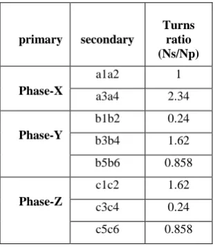
Fig.xvi Three-phase Input voltage waveforms (star-star)
Fig..xvii Three-phase Input current waveforms (star-star)
Peak value of voltage is 400V and current is 15A.
OUTPUT WAVEFORMS
Fig.xviii Five-phase output voltage waveforms (star-star)
Fig.xix Five-phase output current waveforms (star-star)
[image:5.595.99.255.464.644.2]International Journal of Emerging Technology and Advanced Engineering
Website: www.ijetae.com (ISSN 2250-2459,ISO 9001:2008 Certified Journal, Volume 3, Issue 5, May 2013)
803
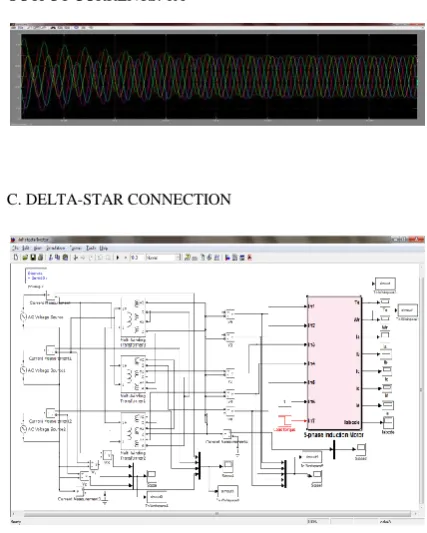
B. DELTA-STAR CONNECTION
Fig.xx Simulink model of the three-phase to five-phase transformation for Delta-Star connection
INPUT WAVEFORMS
Fig.xxi. Three-phase Input voltage waveforms (delta-star)
Fig.xxii Three-phase Input current waveforms (delta-star)
Peak value is 231V and current is obtained as 26A.
OUTPUT WAVEFORMS
Fig.xxiii Five-phase output voltage waveforms (delta -star)
Fig.xxiv Five-phase output current waveforms (delta -star)
Balanced five-phase output voltage peak value is around 400Vand current is around 10A.
C. STAR-POLYGON CONNECTION
Fig.xxv Simulink model of the three-phase to five-phase transformation for Star-Polygon connection
INPUT WAVEFORMS
Fig.xxvi Three-phase Input voltage waveforms (star-polygon)
Fig.xxvii Three-phase Input current waveforms (star-polygon)
Peak value of voltage is 400V and current is 23A.
OUTPUT WAVEFORMS
Fig.xxviii Five-phase output voltage waveforms(star-polygon)
Fig.xxix Five-phase output current waveforms(star-polygon)
Balanced five-phase output voltage peak value is around 400V and current is around 10A.
D. DELTA-POLYGON CONNECTION
Fig.xxx Simulink model of the three-phase to five-phase transformation for Delta-Polygon connection
INPUT WAVEFORMS
Fig.xxxi Three-phase Input voltage waveforms (Delta-polygon)
Fig.xxxii Three-phase Input current waveforms (Delta-polygon)
International Journal of Emerging Technology and Advanced Engineering
Website: www.ijetae.com (ISSN 2250-2459,ISO 9001:2008 Certified Journal, Volume 3, Issue 5, May 2013)
804
OUTPUT WAVEFORMS
Fig.xxxiii Five-phase output voltage waveforms (Delta-polygon)
Fig.xxxiv Five-phase output current waveforms (Delta-polygon)
Balanced five-phase output voltage peak value is around 400Vand current is around 10A.
IV. FIVE-PHASEINDUCTIONMOTOR
Fig.xxxv Five-phase induction motor model
A. SUBSYSTEM
Fig.xxxvi Subsystem model to obtain Wr and Te
𝐓𝐞 = iqs idr ∗ Llr + ids + idr ∗ M − ids
∗ iqr ∗ Llr + iqs + iqr ∗ M ∗5 2∗
P 2
∗ M
M + Llr
B. ROTOR DYNAMICS
Fig.xxxvii Rotor dynamics model
𝐢𝐪𝐬 = 1
Lls + M Vqe − We ∗ M ∗ idr + Lls + M ∗ ids − M
∗ 1
Llr + M add2 − Rs ∗ iqs
𝐢𝐝𝐬 = 1
Lls + M[Vde + We ∗ Lls + M ∗ iqs + M ∗ iqr
− (M ∗ 1
Llr + M∗ add3) − Rs ∗ ids]
𝐢𝐪𝐫 = 1
Llr + M Vqr − M ∗ 1 Lls + M∗ add − ids ∗ M + Llr + M ∗ idr ∗ We − Wr − Rr ∗ iqr
𝐢𝐝𝐫 = 1
Llr + M[Vdr + We − Wr
∗ M ∗ iqs + Llr + M ∗ iqr
− M ∗ 1
International Journal of Emerging Technology and Advanced Engineering
Website: www.ijetae.com (ISSN 2250-2459,ISO 9001:2008 Certified Journal, Volume 3, Issue 5, May 2013)
805
[image:8.595.312.526.160.427.2]B. STAR-STAR CONNECTION
Fig. xxxviii Simulation circuit for star-star connection
INPUT VOLTAGE: 400V
INPUT CURRENT: 0.15A
OUTPUT VOLTAGE: 400V
MOTOR TORQUE: STARTING TORQUE = 11.5N-M
MOTOR SPEED: 1330 RPM
OUTPUT CURRENTS: 1A
C. DELTA-STAR CONNECTION
Fig. xxxix Simulation circuit for delta-star connection
INPUT VOLTAGE: 231V
INPUT CURRENT: 0.25A
OUTPUT VOLTAGE: 400V
[image:8.595.72.284.175.336.2]International Journal of Emerging Technology and Advanced Engineering
Website: www.ijetae.com (ISSN 2250-2459,ISO 9001:2008 Certified Journal, Volume 3, Issue 5, May 2013)
806
MOTOR SPEED: 1330 RPM
OUTPUT CURRENTS: 1A
Similarly, the induction motor can be used to prove the viability of star-polygon and delta-polygon transformation.
V. FFTANALYSIS
The THD Values of output voltages and currents for star – star transformation is found to have less harmonic distortion when compared to other transformations with RL-load.
Fig.xl FFT Analysis for star-star transformation
THD for star-star transformation was found to be 72.65% of the fundamental in all the signals of output voltage and current where as in delta-star transformation, THD was found to be 80.03% of the fundamental.
Sign al no.
STAR-POLYGON DELTA-POLYGON
THD[volt age] in %
THD[curr ent] in %
THD[volt age] in %
THD[curr ent] in %
1 105.38 49.53 89.89 34.2
2 40.60 20.78 60.98 67.21
3 51.3 65.28 162.17 56.81
4 70.4 33.91 55.89 19.11
5 35.67 68.50 109.05 60.82
The THD for torque and speed in star-star connection, delta-star connection, star-polygon connection and delta-polygon connection with induction motor as load, found to be same i.e..THD in torque=20.03%, THD in motor speed=61.29%
VI. LOADSHARING
Let V1*I1 = S1, where V1 and I1 are input phase voltage and current, respectively, and
S1 is average per phase input voltampere (VA). Also, let V2*I2 =S2, where V2 and I2 are output phase voltage and current, respectively, and S2 is per phase output VA. After neglecting the losses, we have : 3S1 = 5 S2 .
VII. CONCLUSION
This paper proposes a new transformer connection scheme to transform the three-phase grid power to a five-phase output supply. The input and outputs are arranged in four different fashions in order to obtain five-phase balanced output. The connection schemes and the phasor diagram along with the turn ratios are illustrated.
A five-phase induction motor model is used instead of RL-load in order to prove the viability of the transformation system for different connections.
FFT analysis is carried out to calculate the Total Harmonic Distortion (THD) for all the proposed transformations with RL-load and five-phase induction motor model.
International Journal of Emerging Technology and Advanced Engineering
Website: www.ijetae.com (ISSN 2250-2459,ISO 9001:2008 Certified Journal, Volume 3, Issue 5, May 2013)
807
REFERENCES[
1] E. E. Ward and H. Harer, “Preliminary investigation of an inverter-fed 5-phase induction motor,” Proc. Inst. Elect. Eng., vol.116, no. 6, 1969.
[2] G. K. Singh, K. B. Yadav, and R. P. Saini, “Modelling and analysis of multiphase (six-phase) self-excited induction generator,” in Proc. Eight Int. Conf. on Electric Machines and Systems, China, 2005, pp. 1922–1927.
[3] “Multiphase Electric Machines for Variable-Speed Applications” by Emil Levi, Senior Member, IEEE.
[4] “Analysis of Output Current Ripple rms in Multiphase Drives Using Space Vector Approach” by Drazen Dujic, Student Member, IEEE, Martin Jones, Member, IEEE, and Emil Levi, Fellow, IEEE.
[5] “General Model of a Five-Phase Induction Machine Allowing for Harmonics in the Air Gap Field” by Lu´ıs Alberto Pereira, C´esar Cataldo Scharlau, Lu´ıs Fernando Alves Pereira, and Jos´e Felipe Haffner.
[6] “A Novel Three-Phase to Five-Phase Transformation Using a Special Transformer Connection” by Atif Iqbal, Member, IEEE, Shaikh Moinuddin, Member, IEEE, M. Rizwan Khan, Sk.
Moin Ahmed, Student Member, IEEE, and Haithem Abu-Rub, Senior Member, IEEE
[7] “Five-Leg Inverter For Five-Phase Supply”, By K. P. Prasad Rao, B. Krishna Veni, D. Ravithej, , K L University, Andhra Pradesh, INDIA. International Journal of Engineering Trends and Technology- Volume3 Issue2- 2012.
[8] “Five-Phase Induction Motor Drive System Fed from Five-PhaseMatrix-Converter” by Sheriff M. Dabour Abd El-Wahab Hassan Essam M. Rashad, SMIEEE, Tanta University, Egypt.
AUTHORS
MONIKA. N persuing (8th-sem) B.E (Electrical & Electronics Engineering) in Dr. T. Thimmaiah Institute of Technology, K.G.F. VTU
SAMHITA. V persuing (8th-sem) B.E (Electrical & Electronics Engineering) in Dr. T. Thimmaiah Institute of Technology, K.G.F. VTU
SINDHU. M persuing (8th-sem) B.E (Electrical & Electronics Engineering) in Dr. T. Thimmaiah Institute of Technology, K.G.F. VTU
SWETHA. P. V persuing (8th-sem) B.E (Electrical & Electronics Engineering) in Dr. T. Thimmaiah Institute of Technology, K.G.F. VTU
SOMASHEKAR. B received B.E degree (Electrical & Electronics Engineering) in Golden Valley Institute of Technology, K.G.F in 1998 under Bangalore University and M. Tech (VLSI & Embedded Systems) from BMS, VTU in 2010.