www.arpnjournals.com
COMPARATIVE STUDY ON A NEW PERMANENT MAGNET FLUX
SWITCHING MACHINE CONFIGURATION OVER SEGMENTAL AND
SALIENT ROTOR STRUCTURE
M. Jenal, E. Sulaiman
Research Center for Applied Electromagnetics (EMC), Universiti Tun Hussein Onn Malaysia (UTHM) 86400 Parit Raja, Batu Pahat, Johor Malaysia
E-Mail: [email protected], [email protected]
ABSTRACT
In this paper, an investigation of a new structure of alternate circumferential and radial magnetization permanent magnet flux (AlCiRaF) permanent magnet flux switching machine (PMFSM) with different rotor configurations namely segmental rotor (SegR) and salient rotor (SalR) is presented. The proposed designs are briefly compared in regards to topology development, materials and conditions setting as well as properties setting. Consequently, coil arrangement tests are carried out to legalize the machine operating principle including position of each armature coil phase. Furthermore, the flux interaction between PM and armature coil, back emf, cogging torque at various rotor position, initial output power and torque performances are also investigated using 2D finite-element analysis (2D-FEA). The simulated result shows that the proposed 12S-10P AlCiRaF PMFSM with SalR rotor attains its highest output torque performances of 25.5 Nm at maximum Ja of 30Arms/mm2 significantly over 60% greater than that of 12S-8P AlCiRaF PMFSM with SegR configuration.
Keywords: Circumferential PM finite-element analysis (FEA) permanent magnet flux switching motor radial PM salient rotor
segmental rotor
INTRODUCTION
Generally, permanent magnet machine is judged as the most advanced energy converter in terms of establish performance due to its several unique characteristics, including robust construction which is well applied for high-speed operations, high tourque density which leads to high efficiency and zero excitation power requirements that result in unity power factor operation (Rick et al, 2013), (Vartanian et al, 2013). Fundamentally, the major type of this machine can be broken down into 2 clusters namely surface-mounted permanent-magnet (SPM) machines and internally mounted permanent-magnet (IPM) machines (Krizan and Sudhoff, 2013). Nevertheless, the main drawback arises ahead of this group of machine is caused by its non-robust rotor structure as all the magnetizing PMs are either embedded or mounted on the rotor body. Besides, the placement of any active components on rotor piece might result in difficulty for the heat and thermal issues to be efficiently managed (Sulaiman et al, 2013).
Therefore, to overcome this complication, flux switching machine (FSM) has been invented and currently become one of the significant candidate to provide robust rotor and hence eliminating the heat challenge (Sulaiman et al, 2011). Subsequently, flux switching machine was first introduced as a single-phase alternator employing permanent magnet by (Rauch and Johnson, 1955) while the three-phase version was first printed in 1997 (Hoang et al, 1997) where they inherit plentiful advantages from the conventional PM machines. In general, PMFSM machine employs a conventional doubly salient structure, which made up of a simple passive and robust rotor but a rather complicated stator. The mechanically rugged rotor is the similar as that of a switched reluctance machine that results in fast dynamic response. Since all the excitation sources such as the armature windings and PMs are housed in the salient-pole stator, the majority of the heat generated by the losses in those active components during the machine
operation can be effectively dissipated to prevent the active components from being locally overheated, so that good thermal management such as liquid cooling can be easily installed (Thomas et al, 2014). Moreover, PMFSM machine also reveals rather good flux weakening capability.
The aim of this paper is to develop a new class of PMFSM utilizing alternate circumferential and radial
(a)
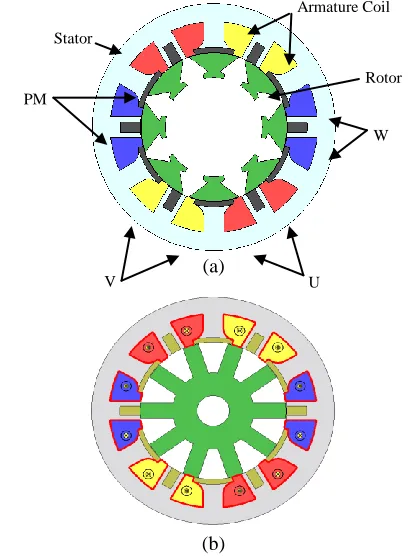
[image:1.595.330.534.465.743.2](b)
Figure 1: AlCiRaF PMFSM topologies. (a) 12S-8P machine with SegR. (b) 12S-10P machine with SalR
U V
W PM
Armature Coil
magnetization flux direction of permanent magnet inside the stator. The proposed topology is then equipped with 2 type of rotors particularly SegR and SalR structures in regards to figure out the best rotor candidate so that the resulting machine can not only inherit the merits of high torque density, high power density, and high reliability but also can effectively enhance the PMs usage efficiency. Finally, both topologies’ corresponding electromagnetic performances, including magnetic field distribution, PM flux linkage, back EMF, output torque and power performances are analyzed using finite element method (FEM).
AlCiRaf PMFSM MACHINE
Design specifications and limitations
The proposed AlCiraf PMFSM is mainly a kind of machine which solitarily utilize PM as magnetizing flux excitation. The objective following manipulating only one source of excitation field is to optimize the capability of PM placed in the stator section. Besides, PM excitation tenders an extra scale of freedom particularly in improving energy efficiency of the traction motors that have been explored extensively over many years.
The design specifications and limitations of the proposed machine are listed in Table 1 comprising both segmental and salient rotors dimension. Pertaining to Figure 1(a), it is noticeable that the designed machine is portraying 12 stator teeth, 6 armature coil slots, 8 segmental type of rotor structures and 12 pieces of PMs with respect to alternate radial and circumferences flux directions. Since the PM volume is limited to only 0.5kg, the final machine is likely to have less weight but high performances in terms of output torque and power. Morevoer, the type of material used in developing the design is Neomax35AH which having coercive force at 20°C and residual flux density of 932kA/m and 1.2T, while for rotor and stator parts are made up of electrical steel coded 35H210.
On the other hand, the 12S-10P AlCiraF PMFSM illustrated in Figure 1(b) is constructed with wound salient type of rotor. In addition, the salient rotor pole configuration is being introduced in this study in order to secure robust structure while rotating at high speed. Consequently, the proposed stator and rotor configurations would assure a simple and effortless in manufacturing process. Besides, the fundamental rotor structure is mechanically robust to spin at high speed because it consists of only laminated electromagnetic sheets. Supposing that only a water-jacket
system is applied as the cooling system of the machine where value of 30Arms/ mm2 is set to be the limit of the armature current density.
Operating principle
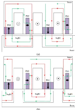
In realizing the flux switching scheme using PMs, the major requirement is that the field excitation is generated by PMs in a similar method to the field winding as depicted in Figure 2 where PM1, PM2, PM3 and PM4 are permanent magnet, SegR1 and SegR2 are segmental rotor structures while armature coils are represented by cross and dot symbols respectively. Circumferential PM flux and radial PM flux are alternately placed to each other where each type of PM is assigned with opposite flux directions. First alignment position in Figure 2(a) demonstrates 2 courses of flux circulations between PM1,PM3 and SegR1 move in clockwise route as well as PM2, PM4 and SegR2 which flow in counterclockwise direction. All the excited fluxes are originally travelling from stator to rotor and move back to stator in order to accomplish 1 full cycle. Meanwhile, the elementary rectiliner map portrayed in Figure 2(b) describes that the fluxes profile is now switched in term of direction as PM1,PM4 and SegR1 form 1 completed flux cycle while PM3, PM2 and SegR2 produce another flux cycle. Red and blue colour of lines represent excited fluxes by circumferential and radial PM respectively.
(a)
[image:2.595.304.559.385.759.2](b)
Figure 2: Principle operation of proposed 12S-8P AlCiRaF PMFSM with SegR rotor structure. (a) 1st alignment position
(b) 2nd alignment position Table 1: Main parameters of ALCIRAF PMFSM machines
Parameters
AlCiRaF PMFSM with
SegR
AlCiRaF PMFSM with
SalR
eh hp fo oN 3
eh hp ot th fhoN 21
eh hp hth fhoN 8 21
Outside diameter of stator 150 mm Width of stator tooth 12.5 mm Width of rotor tooth 40 10 mm Back iron depth of stator 11 mm Motor stack length 70 mm Length of air gap 0.3mm Diameter of rotor 89.7 mm No. of turns per armature coil slot 44
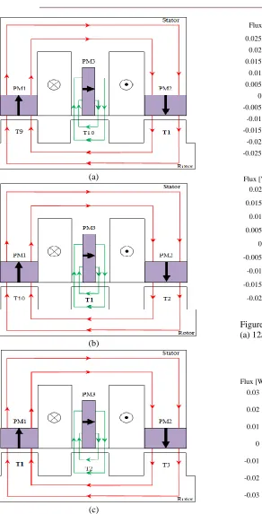
[image:2.595.44.286.646.792.2]On the other hand, Figure 3 illustrates flux characteristics of SalR 12S-10P AlCiRaf PMFSM machine where apparently the excited fluxes by PMs circulating in between stator and rotor fragments and generate a complete flux cycle at three typical rotor positions namely T1, T2 and T3 under one electric cycle. The term ‘‘flux switching’’ is used to explain a machine with respect to the stator tooth flux switches polarity following the motion of a salient pole
rotor. In Figure 3(a), circumferential fluxes of PM1 flow upward from rotor to stator and travel throughout the stator before return back to rotor via PM2 while PM3 supplies radial fluxes from left to the right of stator tooth, in between of armature coils. Under this condition, obviously that rotor tooth T1 is receiving fluxes from stator. Meanwhile, with regards to Figure 3(b), as the rotor moves to the left side which approximately half of electric cycles, rotor tooth T1 starts to circulate fluxes from PM3 within the small area of rotor tooth tip and bring them back to stator to complete one flux cycle. Finally, Figure 3(c) depicts the condition where (a)
(b)
[image:3.595.125.534.60.642.2](c)
Figure 3: Principle operation of the proposed AlCiRaF 12S-10P PMFSM. (a) rotor tooth T1 receives flux from stator via PM2. (b) flux from stator via PM3 to rotor
toot h T1 fed back to stator. (c) flux from rotor tooth T1 leaves rotor to stator via PM1
(a)
[image:3.595.58.350.65.638.2](b)
Figure 4: AlCiRaF PMFSM three-phase flux linkage. (a) 12S-8P machine with SegR. (b) 12S-10P machine
[image:3.595.322.540.473.620.2]with SalR
Figure 5: U flux comparison -0.025
-0.02 -0.015 -0.01 -0.005 0 0.005 0.01 0.015 0.02 0.025
0 60 120 180 240 300 360 Flux [Wb]
Electric Cycle []
U V W
-0.02 -0.015 -0.01 -0.005 0 0.005 0.01 0.015 0.02
0 60 120 180 240 300 360 Flux [Wb]
Electric Cycle []
U V W
-0.03 -0.02 -0.01 0 0.01 0.02 0.03
0 60 120 180 240 300 360 Flux [Wb]
Electric Cycle [°] AlCiRaF PMFSM with segmental rotor
rotor pole T1 is moved to face PM1 and hence passing fluxes upward to stator. Throughout this process, observably that the fluxes within T1 has changed their route from downward to upward direction at three different cycles.
Comparison of AlCiRaF PMFSM with SegR and SalR rotor structure
A. Armature Coil Arrangement Test
With the aim of authenticating the three phase operating principle for both proposed AlCiRaF PMFSM machines as well as to resolve the position of each armature coil phase, coil arrangement tests are carried out where all armature coils are initially wounded in counter-clockwise direction. Subsequently, the computing flux linkages are then evaluated and compared with intention that the armature coils are qualify to be classified according to the conventional three phase system. Figure 4(a) and 4(b) demonstrate the three phase flux linkage of each SegR 12S-8P AlCiRaF PMFSM and SalR 12S-10P AlCiRaf PMFSM respectively as for comparison. Clearly presented that all the examined machines are attaining a successfull fundamental principles of three phase flux linkages eventhough the waveforms emerged from both designs are slightly inidentically solid like sinusoidal curve. On the other hand, comparison in Figure 5 signifies that SegR machine has generated higher flux amplitude approximately spotted at 21.04mWb followed by SalR AlCiRaF PMFSM where 16.25mWb maximum flux amplitude has been achieved.
B. PM Flux Lines and Distributions
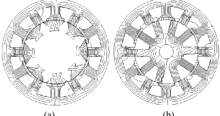
The investigations of flux profiles are carried out under open circuit condition where both machine topologies are compared at zero degree rotor position as shown in Figure 6 and Figure 7 respectively. Evidently, both machines have
surfaced almost identically excited PM flux lines and distributions uniformness as the flux surges from stator to rotor and return back passing through rotor teeth to result in a complete flux cycles of PM. Nonetheless, SalR rotor structure has displayed higher flux concentration at 6 out of its 10 poles hence causing the rotor might easily rotated even at low supply of excited armature flux. However, the maximum flux density at this point is read at estimatedly 2.5T which is equally measured as SegR AlCiRaF 12S-8P PMFSM.
C. Induced Voltage
By revolving both rotor structure at rated pace of 500r/min, the no-load back electromotive force (emf) of the proposed AlCiRaF PMFSM configurations are illustrated in Figure 8. Apparently, SegR proposed machine comprises multiple concerns as the simulated waveform resulted in higher amplitude reading as well as more distorted emergence. On the other hand, SalR type of machine having only highest amplitude of approximately 24V. Moreover, its computed waveform exhibits a more favorable sinusoidal feature.
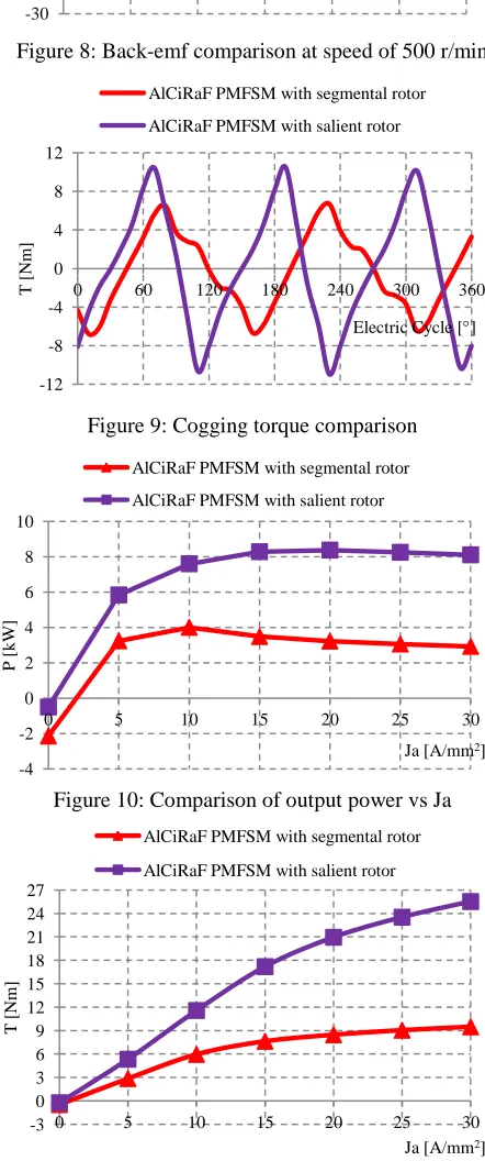
D. Cogging Torque Analysis
Figure 9 points up the comparison of cogging torque over the examined AlCiRaF PMFSMs. In terms of peak to peak measurement, SegR machine has showed the lower result marked at 13.33Nm, approximately 58.36% better than SalR. However, the same rotor structure has also presented
more distorted waveform but nevertheless, the said and undesired drawback is targetedly to be abolished after further appropriate design refinement and optimization.
E. Output Power Analysis
Both configurations of AlCiRaF PMFSMs are analyzed under the same armature current density up to maximum Ja of 30Arms/mm2, respectively. Figure 10 emphasizes that the proposed machine employing SalR has contributed a better output power approximately gauged at 8.11 kW compared to almost 64% weaker performance by the other one which employing SegR type. In further details, as the graph increases from initial position to Ja of 10Arms/mm2, SegR machine has reached the maximum reading of 4 kW but started declining thereafter until Ja of 30 Arms/mm2. Accordingly, the lost occurred throughout this progression is estimatedly 26.75%. On the contrary, SalR type of machine affected by only 3.22% power lost drawback as the graph peaked at Ja of 20Arms/mm2 with output power of 8.38kW.
F. Output Torque Achievement
[image:4.595.56.282.487.606.2](a) (b)
Figure 6: Flux lines: (a) 12S-8P machine with SegR. (b) 12S-10P machine with SalR [image:4.595.308.546.678.775.2]
(a) (b)
Figure 7: Flux distributions: (a) 12S-8P machine with SegR. (b) 12S-10P machine with SalR
Table 2: Performance comparison AlCiRaF PMFSM
with SegR
AlCiRaF PMFSM with
SalR
Flux density 2.5T 2.5T
Resulting data of initial torque performances for both machines are plotted in Figure 11. Obviously, both proposed topologies have demonstrated most likely about similar graph pattern in which SalR structured machine takes place as the higher torque producer with 25.54 Nm maximum achievement compared to SegR rotor design. In fact, at the same current density of 30Arms/mm2, the resulting torque of these two machines are splitted by more than 62.8% diversity. Finally, the overall performances of the proposed machine designs are visualized in Table 2.
CONCLUSION
In this paper, design study of the proposed 12S-8P AlCiRaF PMFSM with SegR and 12S-10P AlCiRaF PMFSM with SalR pole configurations has been inspected and compared. The output performances of both AlCiRaF PMFSMs such as flux capability, initial power and torque output have been comprehensively examined. Consequently, 12S-10P AlCiRaF PMFSM with SalR structure has yielded to carrying more favorable three phase sinusoidal waveforms, lower induce voltage and harmonics as well as higher result of power and torque output. Furthermore, its performances of 25.54Nm output torque and 8.11kW output power are significantly over 60% better than that of SegR configuration thus securing high possibility to achieve much higher performances and more wider range suitability, relatively after further design refinements and optimizations.
ACKNOWLEDGEMENT
This work funded by Research Innovation, Commercialization and Consultancy management (ORICC) with Vot No E15501, Universiti Tun Hussein Onn Malaysia (UTHM) and Ministry of Education Malaysia (MOE).
REFERENCES
Rick, S.; Felden, M.; Hombitzer, M.; Hameyer, K., (2013) "Permanent magnet synchronous reluctance machine - bridge design for two-layer applications," IEEE International Electric Machines & Drives Conference (IEMDC2013), 1376-1383.
Vartanian, R.; Deshpande, Y.; Toliyat, H.A., (2013) "Performance analysis of a rare earth magnet based NEMA frame Permanent Magnet assisted Synchronous Reluctance Machine with different magnet type and quantity," IEEE International on Electric Machines & Drives Conference (IEMDC2013), pp.476-483.
Krizan, J.A.; Sudhoff, S.D., (2013) "A Design Model for Salient Permanent-Magnet Machines With Investigation of Saliency and Wide-Speed-Range Performance," IEEE Transactions on Energy Conversion, vol.28, no.1, pp.95-105.
[image:5.595.54.274.79.234.2]Sulaiman, E.; Khan, F.; Ahmad, M.Z.; Jenal, M.; Zulkifli, S.A.; Bakar, A.A., (2013) "Investigation of field excitation switched flux motor with segmental rotor," IEEE Conference on Clean Energy and Technology (CEAT2013) , pp.317-322.
Figure 8: Back-emf comparison at speed of 500 r/min
[image:5.595.55.276.225.753.2]
Figure 9: Cogging torque comparison
Figure 10: Comparison of output power vs Ja
Figure 11: Comparison of output torque vs Ja -30 -20 -10 0 10 20 30 40
0 60 120 180 240 300 360
emf
[
V
]
Electric Cycle [°] AlCiRaF PMFSM with segmental rotor
AlCiRaF PMFSM with salient rotor
-12 -8 -4 0 4 8 12
0 60 120 180 240 300 360
T
[
N
m]
Electric Cycle [] AlCiRaF PMFSM with segmental rotor
AlCiRaF PMFSM with salient rotor
-4 -2 0 2 4 6 8 10
0 5 10 15 20 25 30
P
[
k
W
]
Ja [A/mm2] AlCiRaF PMFSM with segmental rotor
AlCiRaF PMFSM with salient rotor
-3 0 3 6 9 12 15 18 21 24 27
0 5 10 15 20 25 30
T
[
N
m]
Ja [A/mm2] AlCiRaF PMFSM with segmental rotor
Sulaiman, E.; Kosaka, T.; Matsui, N., (2011) "Design optimization of 12Slot-10Pole hybrid excitation flux switching synchronous machine with 0.4kg permanent magnet for hybrid electric vehicles," IEEE 8th International Conference on Power Electronics and ECCE Asia (ICPE & ECCE2011) , pp.1913-1920.
S. E. Rauch and L. J. Johnson, (1955) “Design principles of flux-switching alternators,” AIEE Trans., Power App. Syst. Part III, vol. 74, no. 3, pp.1261-1268.
E. Hoang, A. H. Ben-Ahmed, and J. Lucidarme, (1997) “Switching flux PM polyphased synchronous machines,” in Proc. 7th Eur. Conf. Power Electron. Appl., vol. 3, pp. 903-908.
Thomas, A.S.; Zhu, Z.Q.; Li, G.J., (2014) "Thermal modelling of switched flux permanent magnet machines," International Conference on Electrical Machines (ICEM), 2014, pp.2212-2217.
X. Zhu, L. Chen, L. Quan, Y. Sun, W. Hua, and Z. Wang. (2012). A New Magnetic-Planetary-Geared Permanent Magnet Brushless Machine for Hybrid Electric Vehicle[J]. IEEE Transactions on Magnetics, 48(11): 4642-4645.
Z.Q. Zhu, and J.T Chen, (2010) "Advanced flux-switching permanent magnet brushless machine," IEEE Trans. Magn., vol 46, no. 6, pp. 1447-1452.
Zulu, A.; Mecrow, B.C.; Armstrong, M., (2012). "Permanent-Magnet Flux-Switching Synchronous Motor Employing a Segmental Rotor," IEEE Transactions on Industry Applications, vol.48, no.6, pp.2259-2267.
Wang, Y.; Huang, Z.W.; Shen, J.X.; Wang, C.F., (2008) "Comparison and study of 6/5- and 12/10-pole permanent magnet flux-switching motors considering flux-weakening capability," International Conference on Electrical Machines and Systems (ICEMS2008), pp.3262-3265.