International Journal of Emerging Technology and Advanced Engineering
Website: www.ijetae.com (ISSN 2250-2459, Volume 2, Issue 5, May 2012)
132
Efficiency Optimization technique for Induction Motor with
implementation of Fuzzy Logic
Swati sharma
1, Vijay Bhuria
2, Divya rai
31PG Student, 2 Assistant Professor, Department of Electrical Engineering M.I.T.S Gwalior
[email protected] [email protected]
Abstract - Fuzzy logic based efficiency optimization technique of induction motor drive is presented in this paper. The purpose of this paper is to investigate the performance of fuzzy logic controller which is applied on three phase induction motor drive. Fuzzy logic is the convenient way to incorporate the knowledge of human experts in to expert system. The performance of suggested technique has been simulated and developed using MATLAB/SIMULINK for dynamic operating condition.
Keywords - Efficiency, optimization, fuzzy logic controller, Induction motor
I. INTRODUCTION
The uses of electricity increasing but engineers thinking for the way to reduces energy losses. Since electric motor in general and induction motor in particular consume a large fraction of electric power. In 1977 Nola introduce a idea of improving the efficiency of induction motor operating at particular load by reducing the air gap flux level.
There are mainly two types of losses in induction motor copper & iron losses. These losses are stator copper losses And rotor copper losses and another type of losses are stray losses ,iron losses and mechanical (friction+windage) Losses. The main losses are 80%of total losses. The focus of this paper is to minimize the losses of induction motor Using fuzzy controller. However in many condition these losses are present due to electromagnetic losses. On the other hand many application which require adjustable speed/torque. The following thing that permit the electromagnetic loss minimize by the different acts as electromagnetic torque is proportional to the vector product of rotor magnetic flux and rotor current. To obtain the same torque with different combination of flux and current values that is necessary. The purpose of this paper is to introduce a maximum efficiency control method which does not require knowledge of machine parameters and yield a true optimum at the any load torque and speed. in many application efficiency optimization of induction motor which is the most electrical motor present an important factor of control especially for autonomous electrical traction.
The very extensive use of induction motor implies that if losses in induction motor drive can reduce by just a few percent. It will have major impact on total electrical energy consumption.
In this paper fuzzy model identification is employed to minimize the induction motor losses. In order to evaluated the optimal magnetizing current & maximum efficiency In study the motor model includes iron losses. simulation Result are compared with those obtained conventional method and the proposed method
II. MODELLING OF INDUCTION MOTOR
The induction motor model can be developed from its fundamental electrical and mechanical equations. In stationary reference frame the voltage equations are given by
Where p indicates the differential operator (d/dt). The stator and rotor flux linkages are defined using their respective self leakage inductances and mutual inductance as given below
The electromagnetic torque in the stationary reference frame is given as
International Journal of Emerging Technology and Advanced Engineering
Website: www.ijetae.com (ISSN 2250-2459, Volume 2, Issue 5, May 2012)
133
III. EQUIVALENT CIRCUIT OF AN INDUCTION MOTOR An induction motor is essentially a transformer. In the transformer the load on the secondary is electrical where as in case of induction motor the load is mechanical which can be replaced by an equivalent electrical load of load resistance RL given by RL = R2/K2 (1/s – 1) where R2
[image:2.595.62.266.254.406.2]is the rotor phase resistance and K is the turn-ratio of rotor to stator. The simplified equivalent circuit of an induction motor is shown in Fig.
Fig 1 equivalent circuit of induction motor
IV. LOSS MINIMIZATION TECHNIQUE
The efficiency of electrical machines depends on the type, size and quotient of partial load over nominal load. Improvement of the efficiency can be obtained with the following methods:
- Reduction of size (replacement of the motor), when the motor permanently operates in an area of partial load. − Voltage reduction, when the motor is operating with light load.
− In 1977, F.J.Nola introduced the idea of improving power factor of lightly loaded induction motor by reducing the stator voltage.
Then this theory was applied for energy, efficient operation of induction motor at light load conditions.
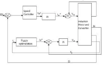
Fig 2 Block diagram for loss minimization
Losses in an IM constitute copper loss and core loss in stator and rotor, mechanical loss, and stray load loss. Core loss and copper loss depend on the magnetic and electric loading of the machine and, therefore, are controllable.
The stray load loss depends mainly on the construction of the motor (type of stator and rotor slots, length of overhang, etc.) and also on the harmonics in the supply voltage. Usually, for a given motor and specified load, the sum of stray load loss and the mechanical loss do not exceed 30% of the total losses and may be assumed to remain constant. Thus, the motivation of loss minimization is to look for an optimum balance of the variable losses to make the total loss minimum. So far, efforts on loss minimization are put into three major directions: 1) through improved design of the motor and converter; 2) by better management to operate a group of motors in a more efficient way; and 3) by introducing better control techniques. Therefore, investigation is focused on better control techniques to yield loss minimization.
A. Loss Model Control (LMC)
[image:2.595.324.534.469.534.2]Based on the IM loss model the optimum flux is computed analytically. Without extra hardware, LMC can be conveniently realized. However, it must need an accurate knowledge of motor parameters, which change considerably with temperature, saturation, skin effect, etc.
Fig a Block diagram for the model based control strategy
B. On-Line Power Measure Search Control
[image:2.595.62.267.601.730.2]International Journal of Emerging Technology and Advanced Engineering
Website: www.ijetae.com (ISSN 2250-2459, Volume 2, Issue 5, May 2012)
134
V. FUZZY LOGIC APPROACH
The fuzzy logic is an aggregation of rules, based on the input state variables condition with a corresponding desired output. A mechanism must exist to decide on which output, or combination of different outputs, will be used since each rule could conceivably result in a different output action. Fuzzy logic provides machinery for carrying out approximate reasoning processes when the available information is uncertain, incomplete or vague. The success of this methodology has been demonstrated in a variety of fields. A fuzzy logic controller essentially embeds the experience and intuition of a human plant operator, and sometimes those of the designer of the plant
VI. IMPLEMENTATION OF FUZZY LOGIC CONTROLLER,INDUCTION MOTOR PARAMETER To obtain fuzzy based model of the motor, the training system derives information from two main sources, a. The efficiency curves of the motor, which provides important information about the appropriate voltage to be applied
b. The dynamic real time operating waveforms of the motor, which can include real-time operating effects, During the training phase, each input-output data pair, which consists of a crisp numerical value of measured quantities, is used to generate the fuzzy rules.
To determine a fuzzy rule from each input-output data pair, the first step is to find the degree of each data value in every membership region of its corresponding fuzzy domain. The variable is then assigned to the region with the maximum degree. When each new rule is generated from the input-output data pairs, a rule degree or truth is assigned to that rule, where this rule degree is defined as the degree of confidence in the developed method a degree is assigned which is the product of the membership function degree of each variable in its respective region. Every training data set produces a corresponding fuzzy rule that is stored in the fuzzy rule base. Therefore, as each input output data pair is processed, rules are generated. A fuzzy rule or knowledge base is in the form of two dimensional tables, which can be looked up by the fuzzy reasoning mechanism. Speed/slip error is calculated with comparison between reference speed/slip and speed/slip signal feedback.
Speed/slip error and speed/slip error changing are fuzzy controller inputs. A fuzzy logic controller operation is based on the rules formed. Simulation studies are performed to validate a theoretical development. Simulation model was made in Simulink-Matlab software. Power losses and drive performances were veteran with efficiency controller and compared with the case when efficiency controller is not included in a drive.
For example, the control rule might be: if the output is lower than the requirement and the output is dropping moderately then the input to the system shall be increased greatly. Such a rule has to be converted into a more generally statement for application to fuzzy algorithms. To achieve this the following terms are defined: error equals the set point minus the process output, error change equals error from the process output minus the error from last output and control input ap plied to the process.
PARAMETER VALUES
Shaft power 2.2KW
no. of pole pairs 2
Stator resistance 2.4 OHM
Total leakage factor 0.136
Mutual inductances 0.1 H
Stator (rotor) self inductances
0.121 H
Inertia movement 0.013 SI
Viscous fraction coefficient 0.002 SI
International Journal of Emerging Technology and Advanced Engineering
Website: www.ijetae.com (ISSN 2250-2459, Volume 2, Issue 5, May 2012)
135
The given table shows the paprmeter of induction motor which we use in simulation of induction motor to optimize the efficiency of induction motor. In this paper we calculate fuzzy rule shown in table.
VII. RULES FOR FUZZY CONTROLLER
The FLC is a knowledge-based control that uses fuzzy set theory and fuzzy logic for knowledge representation. This paper presents a novel fuzzy logic controller suitable for efficiency optimization of induction motor drives. Now with the help of these fuzzy rules we can find the surface of FLC . With a fuzzy logic controller we can control the amplitude of starting current and also save more energy during this time. In addition the cost and complexity of controller is reduced when it is designed by fuzzy method, because it does no need the exact model of system. The rule represents that i)NL negative large ii)negative medium iii) negative small iv)zero v) positive small vi) positive medium vii) positive large. These are the rule which help us in find the surface of fuzzy controller and represents change in efficiency.
VIII. RESULT AND DISCOSION
To simulate the model in machine the simulink model has to be initialized first so that it will know all the machine parameters. First this reason initialization file containing all the machine parameter is formed. The file assign values to the machine parameter variables in the simulink model. in this paper the implementation of fuzzy logic controller is shows to find out the efficiency of induction motor.
IX. MODEL IN SIMULINK
p8 p7 p6 p5 p4 p3 p2 p1 VSI3 VSI2 VSI1 VSI VS3 VS2 v + -VC v + -VB2 v + -VB1 v + -VB v + -VA3 v + -VA2 v + -VA1 v + -VA 1 Slider Gain1 Scope8 Scope7 Scope6 Scope5 Scope4 Scope3 Scope2 Scope1 Scope node 10 node 10 [A] Goto3 [A] Goto2 [A] Goto1 [A] Goto 1 Gain2 1 Gain1 1 Gain signalout G2 signalout G1 Fuzzy Logic Controller [A] From3 [A] From2 [A] From1 [A] From Divide5 Divide4 Divide3 Divide2 Divide1 0 Display9 0 Display8 0 Display7 0 Display6 0 Display5 0 Display4 0 Display3 0 Display2 0 Display18 0 Display17 0 Display16 0 Display15 0 Display14 0 Display13 0 Display12 0 Display11 0 Display10 0 Display1 0 Display 1 Constant5 1 Constant4 1 Constant3 1 Constant2 1 Constant1 s -+ CS6 s -+ CS5 s -+ CS4 s -+ CS3 s -+ CS2 s -+
CS1 Tm m
A B C a b c Asynchronous Machine SI Units2 Tm m A B C a b c Asynchronous Machine SI Units1 Vabc IabcPQ 3-phase Instantaneous Active & Reactive Power1 Vabc IabcPQ 3-phase Instantaneous Active & Reactive Power Vabc Iabc A B C a b c 3 phase measurement2 Vabc Iabc A B C a b c 3 phase measurement1
X.
CONCLUSIONSThis paper has presented an fuzzy-based scheme for induction motor drive leading to energy saving. The proposed scheme uses information on speed and torque of the motor to generate the appropriate voltage amplitude that saves the energy. An fuzzy-based model has been configured using a Matlab simulink. Implementation of this algorithm for efficiency improvement next results is obtained.
η/∆η NL NM NS ZZ PS PM PL
NL NL NL NL NM NM NS ZZ
NM NL NM NM NS NS ZZ PS
NS NM NM NS NS ZZ PS PS
ZZ NM NS NS ZZ PS PS PM
PS NS NS ZZ PS PS PM PM
PM NS ZZ PS PS PM PM PL
International Journal of Emerging Technology and Advanced Engineering
Website: www.ijetae.com (ISSN 2250-2459, Volume 2, Issue 5, May 2012)
136
REFERENCES
[1 ] El-SADEK, M. Z.—El-SAADY, G.—ABO-El-SAUD, M. A Variable Structure Adaptive Neural Network Static VAR Controller,Electric Power Systems Research 45 (1998)
[2 ] CHERN, T. L.—CHANG, J.—CHANG, G. K. : DSP-Based Integral Variable Structure Model Following Control for BrushlessDC Motor Drivers, IEEE Transactions on Power Electronics, 12 No. 1 (1997)
[3 ] LIN, F. J.—CHOU, W. D. : An Induction Motor Servo Drive Using Sliding-Mode Controller
with Genetic Algorithm, Electric Power Systems Research 64 (2003)
[4 ] J. Faiz, M.B.B. Sharifian, ―Optimal design of three-phase Induction Motors and their comparison with a typical industrial motor,‖Computers and Electrical Engineering, vol. 27, 2001, pp. 133-144.
[5 ] O. Muravlev, et al, ―Energetic parameters of induction Motors as the basis of energy saving in a variable speed drive, ‖ Electrical Power Quality and Utilization, Vol. IX, No. 2, 2005.
[6 ] Christian Koechli, et al, ―Design optimization of induction motors for aerospace applications, ‖ IEEE Conf. Proc. IAS, 2004, pp. 2501-2505.
[7 ] Z. Maljkovic, M. Cettolo, et.al, ―The impact of the induction motor on short-circuit current‖, IEEE Ind. Application Magazine, 2001.
[8 ] M. K. Yoon, C. S. Jeon, S. K. Kauh,. ―Efficiency increase of an induction motor by improving cooling performance,‖ IEEE Trans. Energy Conversion, 2002.
[9 ] C. Palanichamy, C. Nadarajan, P.Naveen, N. S. Babu, Dhanalakshmi, ―Budget constrained energy conservation- An experience with a textile industry,‖ IEEE Trans. Energy Conversion, Vol. 16, No. 4, 2001.
[10 ]R. H. A. Hamid, A. M. A. Amin, R. S. Ahmed, A. El-Gammal, ―New technique for maximum efficiency of induction motors based on PSO,‖ IEEE conference proceedings, 2006.
[11 ]D. H. Kim, ―GA-PSO based vector control of indirect three phase induction motor,‖ Applied Soft Computing, Vol. 7, No.2, 2006.-611.
[12 ]I. Kioskesidis, N. Margaris, ―Loss minimization in scalar controlled induction motor drives with search controller,‖ IEEE Trans. Power Electronics, Vol. 11, No. 2, 1996.
[13 ]M. Cacciato, A. Consoli, G. Scarcella, G. Seelba, A. Testa, ―Efficiency optimization technique via constant optimal slip control of induction motor drives,‖ IEEE conference proceedings on Power Electronics, Electric Drives, automation, and Motion, 2006.