International Journal of Emerging Technology and Advanced Engineering
Website: www.ijetae.com (ISSN 2250-2459,ISO 9001:2008 Certified Journal, Volume 4, Issue 12, December 2014)
264
Multi-String Seven-Level Inverter with Novel PWM Control
Scheme for Renewable Power Generation System
L. Agatha Nancy
1, T. Rajesh
2, G. J. Pauline Jothi Kiruba
31
PG Scholar, Info Institute of Engineering, Coimbatore, India
2,3Assistant Professor, Info Institute of Engineering, Coimbatore, India
Abstract—In this paper, a seven-level inverter is developed and applied for injecting the real power of the renewable power into the grid to reduce the switching power loss, harmonic distortion ,and electromagnetic interference caused by the switching operation of power electronic devices. This
paper presents a single-phase multi-string five-level
photovoltaic (PV) inverter topology for grid-connected PV systems with a novel pulse width-modulated (PWM) control scheme. Three PV strings are cascaded together in parallel configuration and connected to a seven-level inverter to produce output voltage in seven levels: zero, 1vdc, 2vdc, 3v
dc,-vdc,-2vdc,-3vdc .Two reference signals that were identical to each
other with an offset that was equivalent to the amplitude of the triangular carrier signal were used to generate PWM signals for the switches. The inverter offers much less total harmonic distortion and can operate at near-unity power factor. The validity of the proposed inverter is verified through simulation and implemented in a prototype. The experimental results are compared with a conventional single-phase multi-string five-level grid-connected PWM inverter.
Keywords— Grid-connected, multilevel inverter, photovoltaic (PV), pulse width-modulated (PWM) inverter,
proportional–integral (PI) current control, Harmonic
distortion, power electronics.
I. INTRODUCTION
The world is concerned with fossil-fuel exhaustion and environmental problems caused by conventional power generation, renewable energy sources, particularly solar and wind energy, have become very popular and demanding. Photovoltaic (PV) sources are used today in many applications because they have the advantages of being maintenance and pollution free. In 2013, the fast-growing capacity of worldwide installed solar PV increased by 38 percent to 139 gig watts (GW). This is sufficient to generate at least 160 terawatt hours (TWh) or about 0.85 percent of the electricity demand on the planet. China, followed by Japan and the United States, is now the fastest growing market, while Germany remains the world's largest producer, contributing almost 6 percent to its national electricity demands.
Solar-electric energy demand has grown consistently by 20%–25% per annum over the past 20 years, which is mainly due to the decreasing costs and prices. This decline has been driven by the following: 1) an increasing efficiency of solar cells; 2) manufacturing-technology improvements; and 3) economies of scale. A PV inverter, which is an important element in the PV system, is used to convert dc power from the solar modules into ac power to be fed into the grid. A general overview of different types of PV inverters is given in and. This paper presents a string seven-level inverter for PV application. The multi-string inverter shown in Fig.(1) is a further development of the string inverter, where several strings are interfaced with their own dc–dc converter to a common dc–ac inverter .This is beneficial, compared with the centralized system, because every string can be controlled individually. Thus, the operator may start his/her own PV power plant with a few modules. Further enlargements are easily achieved because a new string with a dc–dc converter can be plugged into the existing platform
International Journal of Emerging Technology and Advanced Engineering
Website: www.ijetae.com (ISSN 2250-2459,ISO 9001:2008 Certified Journal, Volume 4, Issue 12, December 2014)
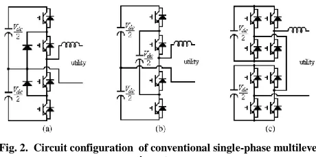
265 Two diodes are used to conduct the current loop, and four power electronic switches are used to control the voltage levels. The output voltage of the basic diode-clamped multilevel inverter has three levels. The voltage
difference of each level is Vdc/2 (the voltage on a
capacitor).Since the voltages of two dc capacitors are used
to form the voltage level of the multilevel inverter, the
[image:2.612.52.282.247.361.2]voltages of these two dc capacitors must be controlled to be equal.
Fig. 2. Circuit configuration of conventional single-phase multilevel inverter.
(a) Diode clamped. (b) Flying capacitor. (c) Cascade H-bridge.
The control for balancing these two dc capacitors is very important in controlling the diode-clamped multilevel inverter, and it is very hard under the light load. If the seven-level output voltage is expected, extra 4 diodes and six power electronic switches are required. Fig. 2(b) shows the circuit configuration of a basic flying capacitor multilevel inverter. As can be seen, it is configured by three dc capacitors and four power electronic switches. The
voltage on each dc capacitor is controlled to be Vdc/2, and
the output voltage of the basic flying capacitor multilevel inverter has three levels. The voltage difference of each
level is also Vdc/2 (the voltage on a dc capacitor). These
three dc capacitors must be controlled for maintaining their
voltages to be Vdc/2 in the charge and discharge processes.
Therefore, its control circuit is more complicated. If
seven-leveloutput voltage is required, two extra dc capacitor and
eight power electronic switches are required. Fig. 2(c) shows the circuit configuration of the basic cascade H-bridge multilevel inverter. As can be seen, it is configured by two full-bridge inverters connected in cascade. The dc
bus voltage of each full-bridge inverter is Vdc/2, and the
output voltage of each full-bridge inverter can be controlled
to be Vdc/2, 0, and −Vdc/2. Thus, the voltage levels of the
output voltage of the cascade full-bridge multilevel inverter
are Vdc, Vdc/2, 0, −Vdc/2, and −Vdc.
This topology has advantages of fewer components being required compared with other multilevel inverters under the output voltage with the same levels, and its hardware circuit can be modularized because the configuration of each full bridge is the same. However, this topology has the disadvantages that two independent dc voltage sources are required. In this paper, a seven-level inverter is developed and applied for injecting the real
power of the renewable power into the grid. This
seven-level inverter is configured by two dc capacitors, a dual-buck converter, a full-bridge inverter, and a filter. The seven-level inverter generates an output voltage with seven levels and applies in the output stage of the renewable power generation.PV string1,PV string 2, and PVstring 3 are connected to the inverter via the dc–dc boost converters. Because the proposed inverter is used in a grid-connected PV system, the utility grid is used instead of a load. The dc–dc boost converters are used to track the maximum power point (MPPT) independently and to step
up inverter output voltage Vinv to be more than 2 of grid
voltage Vg to ensure power flow from the PV arrays into
the grid. As a step-up transformer with a ratio of 1 : 2 is
used , Vinv should be,
Or
Therefore, the dc-bus voltage is assumed to be approximately 200 V. In this paper, the multi-string approach is adopted because each dc–dc converter can independently perform MPP tracking (MPPT) for its PV strings.Therefore, the dc-bus voltage is assumed to be approximately 200 V. In this paper, the multi-string approach is adopted because each dc–dc converter can independently perform MPP tracking (MPPT) for its PV
strings. This will compensate for mismatches in panels of
like manufacture, which can be up to 2.5% [17]. It offers the further advantage of allowing panels to be given different orientations and so open carrier and reference
signals for different values of M.
(1) If M >1, a higher harmonic in the phase waveform is
obtained. Therefore, M is maintained between zero and
International Journal of Emerging Technology and Advanced Engineering
Website: www.ijetae.com (ISSN 2250-2459,ISO 9001:2008 Certified Journal, Volume 4, Issue 12, December 2014)
266
(2) the amplitude of the carrier signal, i.e., M >1, this will
lead to over modulation. Large values of M in sinusoidal
[image:3.612.52.289.171.347.2]PWM techniques lead to full over modulation .
Fig. 3. Circuit Diagram of Seven-level Inverter..
Furthermore, a greater tolerance to localized shading of panels can be achieved. Another advantage of multi-string configuration is that the mixing of different sources becomes possible, i.e., existing PV panel strings could be extended by adding new higher output panels without compromising the overall string reliability or performance. Other than that, greater safety during installation and maintenance adds to the advantages of multi-string configuration. Depending on the design, each converter module may be able to isolate its connected power source so that the wiring of series or parallel connection of these strings can be performed safely .The power-source-converter connection is a safe low-voltage connection.
II. PWMMODULATION
A. Modulation Index
Modulation index Ma for a five-level PWM inverter is
givenas.
Where Ac is the peak-to-peak value of carrier and Am is
the peak value of voltage reference Vref . Because, in this
paper, two reference signals that are identical to each other are used, (3) can be expressed in terms of the amplitude of
carrier signal Vc by replacing Ac with Vc, and Am = Vref1
= Vref2 = Vref. output voltage produced by comparison of
the two reference signals and the carrier signal can be expressed as,
If there are P pulses per quarter period, and it is an odd
number, coefficients Bn and Ao would be zero, where n is
an even number. Therefore, the (5) can be rewritten as
B. Control System Algorithm and Implementation.
One of the problems in the PV generation systems is that the amount of electric power generated by the solar arrays is always changing with weather conditions, i.e., the intensity of solar radiation. An MPPT method or algorithm, which has quick response characteristics and is able to make good use of the electric power generated in any weather, is needed to solve the aforementioned problem In this paper, the perturb-and-observe algorithm is used to extract maximum power from the PV arrays and deliver it to the inverter. The feedback controller used for the inverter is the PI algorithm .
Fig. 4. MPPT flowchart.
The current injected into the grid, which is also known
as grid current Ig, is sensed and fed back to a comparator,
which compares it with reference current Iref . Iref is
obtained by sensing utility grid voltage Vg. The sensed Vg
signal is converted into a reference signal before it is
multiplied with variable m .
C. Simulation and Experimental Results
[image:3.612.339.564.369.565.2]International Journal of Emerging Technology and Advanced Engineering
Website: www.ijetae.com (ISSN 2250-2459,ISO 9001:2008 Certified Journal, Volume 4, Issue 12, December 2014)
267 The developed five-level inverter is superior to the conventional five-level inverters.
Harmonic reduction has been obtained and THD has been reduced.
TABLEI
COMPARISONOFSEVEN-LEVELINVERTERS
Conventional Proposed
Diode-Clamped Flying Capacitors Cascade H-bridge 7-level Inverter
Power Electronic switches
12 12 12 10
Balancing Voltage Of Capacitors
hard hard hard easy
The above table represents the comparison of conventional and proposed technique and the advantage of following the proposed model is well understood with this.
[image:4.612.98.591.197.588.2]Fig. 5.Simulation Diagram
[image:4.612.56.295.388.596.2]International Journal of Emerging Technology and Advanced Engineering
Website: www.ijetae.com (ISSN 2250-2459,ISO 9001:2008 Certified Journal, Volume 4, Issue 12, December 2014)
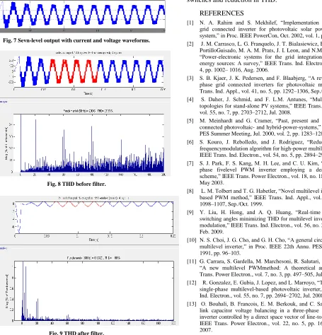
[image:5.612.60.515.224.698.2]268 Fig. 7 Sevn-level output with current and voltage waveforms.
Fig. 8 THD before filter.
Fig. 9 THD after filter.
III. CONCLUSION
The THD level has been reduced considerably. The THD in Conventional method is above 4% but here in seven-level Method THD has been reduced to about 1.80%. The power factor is also maintained near unity. Reduced number of switches has been used in this system. Comparatively this system is more efficient than the conventional system because of the reduced number of switches and reduction in THD.
REFERENCES
[1] N. A. Rahim and S. Mekhilef, ―Implementation of three-phase
grid connected inverter for photovoltaic solar power generation system,‖ in Proc. IEEE PowerCon, Oct. 2002, vol. 1, pp. 570–573.
[2] J. M. Carrasco, L. G. Franquelo, J. T. Bialasiewicz, E. Galvan,R. C.
PortilloGuisado, M. A. M. Prats, J. I. Leon, and N.Moreno-Alfonso, ―Power-electronic systems for the grid integration of renewable energy sources: A survey,‖ IEEE Trans. Ind. Electron., vol. 53, no. 4, pp. 1002– 1016, Aug. 2006.
[3] S. B. Kjaer, J. K. Pedersen, and F. Blaabjerg, ―A review of
single-phase grid connected inverters for photovoltaic modules,‖ IEEE Trans. Ind. Appl., vol. 41, no. 5, pp. 1292–1306, Sep./Oct. 2005. [4] S. Daher, J. Schmid, and F. L.M. Antunes, ―Multilevel inverter
topologies for stand-alone PV systems,‖ IEEE Trans. Ind. Electron., vol. 55, no. 7, pp. 2703–2712, Jul. 2008.
[5] M. Meinhardt and G. Cramer, ―Past, present and future of grid-connected photovoltaic- and hybrid-power-systems,‖ in Proc. IEEE-PES Summer Meeting, Jul. 2000, vol. 2, pp. 1283–1288.
[6] S. Kouro, J. Rebolledo, and J. Rodriguez, ―Reduced
switching-frequencymodulation algorithm for high-power multilevel inverters,‖ IEEE Trans. Ind. Electron., vol. 54, no. 5, pp. 2894–2901, Oct. 2007. [7] S. J. Park, F. S. Kang, M. H. Lee, and C. U. Kim, ―A new single-phase fivelevel PWM inverter employing a deadbeat control scheme,‖ IEEE Trans. Power Electron., vol. 18, no. 18, pp. 831–843, May 2003.
[8] L. M. Tolbert and T. G. Habetler, ―Novel multilevel inverter
carrier-based PWM method,‖ IEEE Trans. Ind. Appl., vol. 35, no. 5, pp. 1098–1107, Sep./Oct. 1999.
[9] Y. Liu, H. Hong, and A. Q. Huang, ―Real-time calculation of
switching angles minimizing THD for multilevel inverters with step modulation,‖ IEEE Trans. Ind. Electron., vol. 56, no. 2, pp. 285–293, Feb. 2009.
[10] N. S. Choi, J. G. Cho, and G. H. Cho, ―A general circuit topology of
multilevel inverter,‖ in Proc. IEEE 22th Annu. PESC, Jun. 24–27, 1991, pp. 96–103.
[11] G. Carrara, S. Gardella, M. Marchesoni, R. Salutari, and G. Sciutto,
―A new multilevel PWMmethod: A theoretical analysis,‖ IEEE Trans. Power Electron., vol. 7, no. 3, pp. 497–505, Jul. 1992.
[12] R. Gonzalez, E. Gubia, J. Lopez, and L. Marroyo, ―Transformerless
single-phase multilevel-based photovoltaic inverter,‖ IEEE Trans. Ind. Electron., vol. 55, no. 7, pp. 2694–2702, Jul. 2008.
International Journal of Emerging Technology and Advanced Engineering
Website: www.ijetae.com (ISSN 2250-2459,ISO 9001:2008 Certified Journal, Volume 4, Issue 12, December 2014)
269
[14] C. Xia, X. Gu, T. Shi, and Y. Yan, ―Neutral-point potential
balancing of three-level inverters in direct-driven wind energy conversion system,‖ IEEE Trans. Energy Convers., vol. 26, no. 1, pp. 18–29, Mar. 2010.
[15] A. Nami, F. Zare, G. Ledwich, A. Ghosh, and F. Blaabjerg,
―Comparisonbetween symmetrical and asymmetrical single phase multilevel inverter with diode-clamped topology,‖ in Proc. IEEE Power Electron. Spec. Conf., Jun. 2008, pp. 2921–2926.
[16] X. Ruan, B. Li, Q. Chen, S. C. Tan, and C. K. Tse, ―Fundamental considerationsof three-level dc–dc converters: Topologies, analyses, and control,‖IEEE Trans. Circuits Syst. I: Reg. Papers, vol. 55, no. 11, pp. 3733–3743,Dec. 2008.T.
[17] Noguchi, S. Togashi, and R. Nakamoto, ―Short-circuit pulse-based maximum-power-point tracking method for multiple photovoltaic-andconverter system,‖ IEEE Trans. Ind. Electron., vol. 49, no. 1, pp. 217–223, Feb. 2002.
[18] V. G. Agelidis, D. M. Baker, W. B. Lawrance, and C. V. Nayar, ―A