International Journal of Emerging Technology and Advanced Engineering
Website: www.ijetae.com (ISSN 2250-2459,ISO 9001:2008 Certified Journal, Volume 3, Issue 10, October 2013)
Modeling, Analysis and Controlling of A STATCOM for
Power System Stability on Basis of Modulation Index
J. K. Moharana1, A. Das2
Department of Electrical and Electronics Engineering, GITA, BBSR, Odisha Abstract-- The STATCOM (STATic synchronous
COMpensator) is increasingly popular in Power System applications. In general, power factor and stability of the utility system can be improved by STATCOM.Specially, STATCOM can stabilize a given node voltage and compensate the power factor of the system and also load by that node. The steady state and dynamic performance of STATCOM are very critical to the performance of the power system. These performances depend on the modulation index of the converter. The concept of SVPWM (Space Vector Pulse Width Modulation) is extended, in principle, for the inverter switching of STATCOM.The SVPWM gives a greater value of modulation factor in the undermodulation as well as the overmodulation range compared to Sine PWM (SPWM). A PI and an H Controller have been designed for closed-loop
control of the system. It is found through simulation that, H
controller gives better responses than PI controller.
Keywords-- H Controller, PI Controller, SPWM,
STATCOM, and SVPWM
I. INTRODUCTION
In recent years Power Systems are highly complex with long distance transmission lines. The interconnected grids tend to unstable as the heavy loads vary dynamically in their magnitude and power-factor. Power System stability is a key issue to determine the capacity of transmitted power, especially in a deregulated market. Hence new transmission systems are expensive and take considerable amount of time to build up. So, in order to meet increasing power demands, utilities must rely on power export/import arrangements through the existing transmission systems. Power Electronics Devices are gaining popularity for applications in the field of power transmission and distribution systems. The reactive power (VAR) compensation and control have been recognized [1] as an efficient & economic means of increasing power system transmission capability and voltage stability. The FACTS (Flexible AC Transmission Systems) device, such as STATCOM has been introduced more recently. So STATCOM, employing a VSI with a fixed dc link capacitor is a static replacement of synchronous condenser.
In similarly, the firing instant of the 3-phase inverter controls the VAR flow into or out of the STATCOM. Large numbers of capacitor banks or any other passive elements are no more required. Only a fixed set of capacitor provides the required VAR control. The controllable reactive power allows for a rapid control of bus voltage and power factor to the system or to the load end. It offers several advantages over conventional thyristorised converter [2] in terms of speed of response, flicker compensation, flexibility, and minimal interaction with the supply grid. Hence STATCOM is playing increasingly important roles in reactive power provision for power factor correction and voltage support because of its attractive steady state performance and operating characteristics. As power system becomes more complex and more nonlinear loads, it is very critical to control its transient responses. Therefore, it is necessary to study STATCOM dynamic characteristics and capabilities to improve transient stability. In [3] Moran et al have shown in details how the utilization of SPWM techniques reduces harmonic distortion. It has also been shown that an increase of modulation index reduces the size of the link reactor and stress on switches, which are significant issues in practical implementation. The modeling and analysis of STATCOM steady state and dynamic performance with conventional control method have been studied in [4]. Further in [5] Draon et al have modeled the Advanced Static VAR Compensator (ASVC) with SPWM technique to show that a higher modulation index (MI) improves the dynamic response of the system. It also reduces the size of the steady state voltage required on the D.C. link capacitor. However SPWM has its own limitations in the over modulation range. In [6] the dynamic responses and steady state behavior of STATCOM with SVPWM has been studied and the advantages of introducing SVPWM inverter with higher values of MI are highlighted. It is also shown that a PI controller designed on the basis of a linearized model of the STATCOM improves the response significantly.
International Journal of Emerging Technology and Advanced Engineering
Website: www.ijetae.com (ISSN 2250-2459,ISO 9001:2008 Certified Journal, Volume 3, Issue 10, October 2013)
Also the M.I. of the inverter is to be varied over a wide range. The inherently nonlinear system therefore also experiences plant parameter variation over a wide range. In this work, it is shown that the PI controller designed on the basis of the plant model, linearized about a particular operating point, cannot handle the plant parameter variation over the entire range. As a remedy the plant parameter variation is included as plant uncertainty and a controller based on H optimization is used. This gives significant
improvement in plant response on variation of m.
In this paper, an analysis of STATCOM steady state and dynamic performance with robust control based on modulation indices are carried out and is organized as follows. The paper initially focuses on the modeling of the STATCOM with the system in section II. Section III deals with the steady state and transient responses of the STATCOM of nonlinear system. Section IV deals the transient responses of linearized system. The design and performance of PI controller on linearsied model is described in section V and section VI deals with the design and performance of H Controller with the nominal model
of the system. Finally the section VII concludes with both controllers.
II. MODELLING OF THE STATCOM (a) Operating principles:
The operating principles of the STATCOM are explained through Fig.1. If the fundamental component of the output voltage of the inverter
V
0a is in phase with thesupply voltage,
V
sa, then the current flowing out ortowards the STATCOM is always 900 lagging or leading to the supply voltage due to reactive coupling. When
V
0a isgreater than
V
sa current will lead the supply voltage andthe STATCOM will operate in fully capacitive mode, supplying reactive power to the system as shown in Fig.1 (a). Fig.1 (b) shows the case when
V
0a is smaller thanV
sacurrent will lag the system voltage and the STATCOM will operate in inductive mode absorbing reactive power from the system. However to compensate for the losses of the STATCOM,
V
0a will lag or lead to Vsa in capacitive orinductive mode respectively, to absorb real power from the supply voltage.
(a)
(b)
Fig.1 :(a) for capacitive mode and (b) for inductive mode (b) Modelling:
A mathematical model has been developed referring to Fig.2. The system voltages, VsaVsb and Vsc assumed to be sinusoidal and balanced, can be expressed in (1) and their dq transformations are in (2). The currents flowing into the STATCOM as shown in (4) and their dq transformations are shown in (5) and (6). After rearranging (5) and (6) we get (7). Neglecting harmonic components generated due to switching, the STATCOM output voltages are in (8) where, S is the switching matrix of the STATCOM including the modulation index and is given by(9) and their dq transformation is given in (10).
International Journal of Emerging Technology and Advanced Engineering
Website: www.ijetae.com (ISSN 2250-2459,ISO 9001:2008 Certified Journal, Volume 3, Issue 10, October 2013)
3 2 3 2 3 2 T wt Sin wt Sin wt Sin s V T sc V sb V sa V
-(1)
TCos Sin s V sabc V K sqd
V 0 0
---(2)
Where, K is the Park’s transformation matrix,
2 1 2 1 2 1 ) 3 2 ( ) 3 2 ( ) ( ) 3 2 ( ) 3 2 ( ) ( 3 2 t Sin t Sin t Sin t Cos t Cos t CosK
(3)
abc V sabc V abc i s R abc i dt d sL 0 ---(4)
q V sq V d i s wL q i s R q i dt d sL 0 ---(5)
id Rsid wLsiq Vsd V d dtd s
L 0 ---(6)
od V sd V oq V sq V s L d i q i s L s R s L s R d i q i dt d 1 ---(7)
V
0aV
0bV
0c
T
Sv
dc ---(8)
wt Sin wt Sin wt T Sin m S
3 2 3 2 32
---(9)
V0a V0b V0c
T KSvdc m
0 1 0
Tvdc -(10) Replacing above in (10), q and d axis currents are:
Ls iq VsSin s R q i d 1 ---(11)
The capacitor current and voltage are related by:
i
dc
S
TK
1
i
qi
di
0
T
m
0
1
0
i
qi
di
0
T--(12)dc
i
dC
m
dt
dv
---(13)
Replacing (11) and (13) final state equation in (14), where, qc is output.
Tdc v d i q i Sin Cos s V qc Cos Sin s L s V dc v d i q i C m s L m s L s R w w s L s R dc v d i q i dt d 0 0 0 0 0
---(14)(c) Analysis of m and
As the expression (14) involves modulation index ‘m’
and ‘’, apart from the circuit parameters. It is imperative that the effect of ‘m’ be investigated. The same has been
done in the present work and the results are shown. The previous model in[3] uses SPWM based switching of the inverter. As already pointed out, SPWM has its own known disadvantages in the over modulation range (m 1). Also the fundamental content is maximum 78.5% at m=1 with respect to fundamental content of the square wave inverter. Hence the present work proposes to use SVPWM based inverter. Also the effect of MI shows interesting results in[5],where Table I summarizes the output filter design data associated with the ASVC system for different values of modulation index. Use of higher MI reduces the potential size, weight and cost of the associated reactive components, in precise and continuous reactive power control with fast and different values of THDi.. Table II
reveals that for the same THDi, the higher the modulation
index used for switching pattern, the lower the size of the ac side filter.
III. OPEN LOOP RESPONSE OF THE ORIGINAL SYSTEM (a) Steady State Response:
International Journal of Emerging Technology and Advanced Engineering
Website: www.ijetae.com (ISSN 2250-2459,ISO 9001:2008 Certified Journal, Volume 3, Issue 10, October 2013)
Fig.3-5 shows the steady state response of
d
i
,i
q,v
dc,p
candq
c. All variables are linear function of
. Fig.4 shows the steady state value of dc capacitor voltagev
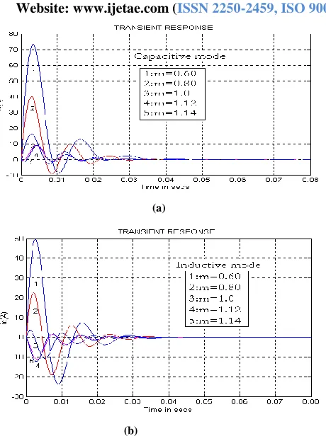
dc is seen to decrease for higher value of m.(b) Transient Response:
The transient response of the system (14) is simulated in MATLAB for an initial condition
v
dc= 400 V and a stepchange in = 100 , the rest of the parameters remaining same as before.Fig.6 to Fig.10 show the transient response of the states iq, id,
v
dc and the outputs qc, and pc . Fig.(a) for capacitive and Fig.(b) for inductive mode respectively. For each case there is a large oscillation during 0-0.04sec and the transients die down at nearly 0.04 sec for higher modulation index and low value of inductance.
Fig.3: Steady state responses of
i
di
qv
dcFig.4: Steady state response of
v
dc for different values of mFig.5: Steady state responses of qc and pc
(a)
(b)
International Journal of Emerging Technology and Advanced Engineering
Website: www.ijetae.com (ISSN 2250-2459,ISO 9001:2008 Certified Journal, Volume 3, Issue 10, October 2013)
(a)
(b)
Fig. 7(a) Transient Response of id and (b) Transient Response of id
(b)
Fig.8:(a)Transient Response of Vdc and (b) Transient Response of Vdc
(a)
(b)
Fig.9(a) Transient Response of qc and (b) Transient Response of qc
[image:5.612.56.286.119.427.2] [image:5.612.55.281.453.599.2] [image:5.612.330.552.473.632.2]International Journal of Emerging Technology and Advanced Engineering
Website: www.ijetae.com (ISSN 2250-2459,ISO 9001:2008 Certified Journal, Volume 3, Issue 10, October 2013)
(b)
Fig.10:(a) Transient Response of pc and (b) Transient Response of pc
IV. LINEARISATION OF THE MODEL
It may be noted that the state equation (14) and with the output equation is nonlinear in . To employ the closed-loop control techniques available in literature this system is linearized about an equilibrium point (Xo, Uo), as given
overleaf, which considers the perturbation to each state about the operating point. Here , a perturbation to , is the input to the model. The linearized state space model is shown in (15).
dc v d i q i Sin s V Cos s V c q Sin s L s V Cos s L s V dc v d i q i C m s L m s L s R s L s R dc v d i q i dt d X 0 0 0 0 0 (15)
V. DESIGN OF PI CONTROLLER FOR THE MODEL AND
CLOSED LOOP RESPONSE
For closed loop operation and to improve the transient response of the original model, a PI controller is designed. The transfer function of the above model is shown in (16). The transfer function of the PI controller is in (17)
C s L s R m s s L s R C s L m s L s R s s C s L m s s L s R s s L s V s s c q s G 2 2 2 2 2 2 2 2 3 2 2 2 ) ( ) ( ) ( ---(16)
s i T K s PIG ( ) 1 1 ---(17)
The value of K and Ti are chosen by trial to improve the
transient response of the system is Kp=K=7.5*10
-6
and
Kl=2.5*10-3. The closed loop transient responses of reactive power of step as well as reference from Fig.11-12 show a considerable lowering in the rise time, settling time on increasing of modulation index. For higher modulation index, each curve settles at nearly 0.02 second. Hence the higher modulation index has good advantage for the controlling of power system stability. For using PI controller and linearising the system, we have to deviate from original system. So the authors are interested to design the Hcontroller.
(a)
(b)
Fig.11 (a) Step Response of qc and (b) Step Response of qc
International Journal of Emerging Technology and Advanced Engineering
Website: www.ijetae.com (ISSN 2250-2459,ISO 9001:2008 Certified Journal, Volume 3, Issue 10, October 2013)
Fig.12 Step Response of qc
VI. CONCLUSION
A PI controller is designed to improve the transient response of nominal model. H Controller has been
designed to improve the transient response of the nominal and along with variation of modulation indices. The modulation index ‘m’ is identified as an important
parameter enhancing the dynamic response reducing the size of the inductor to be used in the ac link. A novel scheme of employing H controller with SVPWM
switching of the converter is proposed to allow use of m 1.
REFERENCES
[1] Johns A.T., Ter-Gazarian,A. and Wame D.F., ”Flexible ac transmission systems(FACTS)”, IEE Power and Energy Series,London,U.K.
[2] Mathus R. M. and Varma R. K., “Thyristors-based FACTS Controllers for Electrical Transmission Systems, EEE Press”, Wiley-Interscience Publication.
[3] Moran L.T., Ziogas P. D. and Joos G., “Analysis and Design of a Three-Phase Synchronous Solid- State Var Compansator”, IEEE Trans. Indus. Appl., Vol. 25, No. 4, 1989, pp. 598-608.
[4] Shauder C. and Mehta H., “Vector analysis and control of advanced static VAR compensators”, IEE Proc, 140, No. 4, July 1993. [5] Rashid H. Muhammad, “Power Electronic Handbook”, Academic
Press, 2001.
[6] Sengupta, M., Moharana, J.K., Sengupta, A “ Study on an Advanced Static VAR Compensator switched from a Space Vector PWM inverter –Analysis, simulation and comparison with the conventional sinusoidal PWM, NPEC 2003, IIT Bombay,16-17 Oct 03 pp 72-78. [7] Bose, B.K., “Modern Power Electronics And AC Drives” LPE
Pearson Education Asia.
[8] Zhou,K.and Doyle,J.C., “Essentials of Robust Control” Prentice Hall, 1997.