Development and Testing of Hybrid Fuzzy Logic
Controller for Car Suspension System
Using Magneto-Rheological Damper
M. M. Rashid
1, N. A. Rahim
2, Member, IEEE,
M. A. Hussain
2, F. Mohamed
2,
and M.A. Rahman
3, Life Fellow, IEEE
Abstract—In this paper, the development of a novel semi- active suspension control of quarter car model using fuzzy logic based controller has been done. The proposed quarter car model can be described as a nonlinear two degrees of freedom system, which is subject to system disturbances from different road profiles. In order to implement the suspension system experimentally, the magneto rheological (MR) fluid has been used as adjustable damper. The MR damper is a control device that consists of a hydraulic cylinder filled with magnetically polarizable particles suspended in a liquid. The MR dampers rapidly dissipate vibration by absorbing energy. In this work, a proportional integral derivative, a fuzzy logic and hybrid controllers are used to control the semi-active car suspension system. Results show that both fuzzy logic and hybrid controllers are quite suitable to eliminate road disturbances to the suspension system considerably as compared to the conventional PID controller.
I.
I
NTRODUCTIONA passive suspension system of an automobile consists of
a spring and a damper unit [1-3]. However, in semi-active
suspension, the value of the damper coefficient can be
controlled. A semi-active suspension is an appropriate solution when it can show reasonable performance as compared to that of an active suspension control. Further more, it does not require external energy. Semi-active dampers change their damping force in real time according to a controller requirement, which is usually based on the system dynamics. The ability to vary the semi-active damping coefficient independent of damper velocity within limits, has prompted many researchers to explore the possibility of improving the suspension performance by using semi-active damper technology.
To implement the relevant control law, the semi-active damper must be adjustable in real time. Currently, semi-active dampers can be adjusted hydraulically or magnetically. The first category uses mechanical valves driven by a solenoid or stepper motor to control damper force in a hydraulic damper. In the latter category, the rheological effect of controllable fluids, such as magneto rheological (MR) fluid or electro rheological (ER) fluid is used to provide adjustable damping forces. Although, mechanically controlled dampers have been
researched and developed extensively, the rheological controllable dampers have not received significant attention.
A semi-active device that is particularly promising for suspension protection is the Magneto-Rheological (MR) damper. The MR dampers use the Magneto-Rheological fluids to produce controllable damper action, and some research on MR fluids deals with characterizing the properties of MR fluids. Lazareva et al. studied the properties of the MR fluids that are based on barium and strontium ferrites and iron oxides [4]. The hydraulic fluids using various combinations of the materials and their properties including MR effects were investigated. Ashour et al. studied the effects of components of the MR on sedimentation of the magnetic particles and initial viscosity [5]. In another study, these authors studied the general composition of MR fluid along with the methods that are used to evaluate the performance of the fluids [6]. Carlson studied the advantages of MR over electro rheological (ER) fluid devices in areas such as working volume of fluid, yield strength and required power [7]. The operational modes of the MR fluid are presented along with the linear fluid damper, the rotary brake, and the vibration damper. Kordonsky developed the concept of the MR converter (or valve) and applies the MR converter to create devices such as the MR linear damper, the MR actuator, and the MR seal [8]. Finally, Bolter examined the rules that should be applied when designing the magnetic circuit for MR devices that are working in different modes of the MR fluid. Bolter also examined the use of permanent magnets in the design of the magnetic circuit to change the operational point of the MR device [9]. When a magnetic field is applied to the fluid, particle chains form, and the fluid becomes a semi-solid and exhibits viscous-plastic behavior similar to that of ER fluid. This controllable change of state with some desirable features such as high strength, good stability, broad operational temperature range and fast response time give rise to stable operation for suspension system applications. The MR fluid dampers are semi-active control devices that use MR fluids to produce controllable damping forces. In particular, it has been found that MR fluids can be quite promising for vibration reduction in an automobile. The responses of the conventional hydraulic fluid based controllers 1Department of Mechatronics
International Islamic University of Malaysia, Kuala Lumpur, Malaysia
2Faculty of Engineering
University of Malaya Kuala Lumpur, Malaysia
3Faculty of Engineering and Applied Science
are sluggish. Modern controllers are needed for fast responses of a car suspension system that uses MR fluids.
The objective of this paper is to develop an intelligent controller for semi-active suspension control and to utilize the ability of the MR damper to reduce vibration of car body experimentally over a wide operating range. The results indicate that this semi-active control system is quite effective for suspension control under various road disturbances for smooth ride of an automobile.
II.
S
EMI-
ACTIVEC
ARS
USPENSIONS
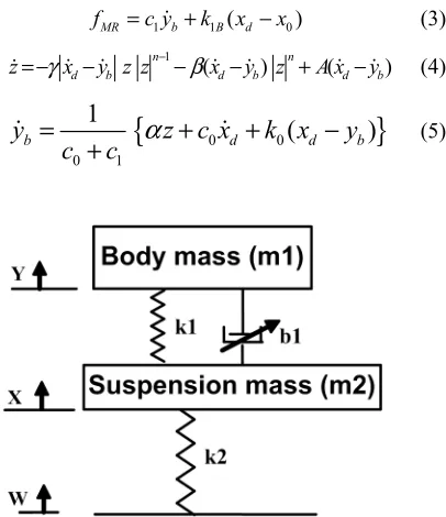
YSTEMA semi-active damper suspension system of an automobile changes the damping force in real time depending on the dynamics of the controlled masses. The effect of control on performance of semi-active suspension has been studied in a two degree of freedom system, as shown in Fig. 1 [10]. It is to be noted that it is based on a quarter car model. The motion equations of the car body and the wheel are given as [11]
1 1( ) 1( )
m y= −k y x− −b y x −
(1)
2 1( ) 2( ).
m y k y x= − −k x w−
(2) The suspension parameters used in the quarter-car model are shown in Table-1. The damping coefficient of MR damper is b1, which is a variable with changing magnetic field depending on the flow of current through the damper coil. The Bouc-Wen model can be used to develop a semi-active control model for the magneto-rheological damper attached to the quarter car semi-active suspension system [12-13]. The model of the MR damper is assumed to be continuous in all the ranges and is numerically stable. The Bouc–Wen model is shown in Figure 2. The force in this system is given by fMR, and it is predicted by this model as
1 1 ( 0)
MR b B d
f =c y +k x −x
(3)
1
( ) ( )
n n
d b d b d b
z=−γ x −y z z − −βx −y z +A x −y (4)
{
0 0}
0 1
1
(
)
b d d b
y
z c x
k x
y
c
c
α
=
+
+
−
+
[image:2.612.360.517.81.134.2] (5)Fig. 1. Modeling of quarter-car suspension system.
TABLE-I
SUSPENSION PARAMETERS USED IN QUARTER-CAR SUSPENSION SYSTEM
Parameter Value m1= Sprung Mass 325 kg
m2= Unsprung Mass 55 kg k1= Suspension Stiffness 42,000 N/m
k2= Tire Stiffness 180,000 N/m
where yb is the internal displacement of the MR damper, xd is the damper displacement in the x-direction, Z is a variable that accounts for the history dependence of the response. The model parameters are given as
a bu
α α α= + (6a)
1 1a 1b
c
=
c
+
c u
(6b)0 0a 0b
c c
= +
c u
(6c) where u is given as the output of first-order filter as(
)
[image:2.612.88.291.453.688.2]u
= −
η
u v
−
(7) Equations (6a) – (6c) are necessary to model the dynamics involved in reaching rheological fluid equilibrium, and in driving the electromagnet in the MR damper. There are few parameters such ask
0,c
0a,c
0b,k
0,c
1a,c
1b,k
1B andx
0 that are required to characterize the MR damper. In the case of the MR damper, the damper force also depends on the coil current directly. Equations (8) – (10) are used to determine the relation between current and relavant parameters of the MR damper as [17]3 2
( ) 1646i i 8701i 1626i 1514
α = − + + (8)
3 2
0( ) 4377 1507 1676 4741
c i = i − i + i+ (9)
3 2
1( ) 9380 5383 4840 2730
c i = − i + i + i− (10)
where i is the current of the damper coil and the additional
variables are constants with the following values: x0 = 0.18 m,
1B
k
= 617.31 N/m, β = 647.46 m-1, n = 10 [14]. Equations (3) – (10) are used for simulation by using the Matlab/Simulink toolbox. The input for this model is current i and the output is the MR damper force. Simulations of proposed model have been done for different input currents and responses of the MR model to these input currents are shown in Fig. 3.1B
k
yb
c1
MR
f k0
c0 Bouc-Wen
d
x
Fig. 3. MR damper force characteristics curve with variable current.
From these dynamic responses of the MR damper, it can be seen that the output force of the MR damper varies uniformly for currents of positive values. But for currents of negative values, the change of forces is found to be not uniform. Although this characteristic is an analytical in nature, but it is an important consideration for designing the experimental semi-action suspension model. When the MR fluid is used to control the suspension, the value of control current is kept within the range of positive values by the controller action.
III.
E
XPERIMENTALS
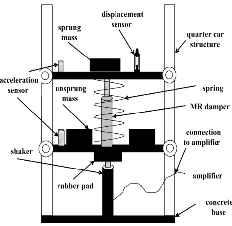
ETUPThe experimental test bench of the quarter-car semi active suspension system consists of the structural setup as well as the control system configuration. The schematic arrangement of the quarter-car apparatus is shown in Fig. 4. The main parts of the real car suspension system are the wheel, wheel axle shaft mass (unsprung mass and sprung mass), car body mass, spring and damper. The wheel shaft mass and car body mass are replaced by two different weight blocks with movable platforms, respectively. Spring and damper are replaced by equivalent spring and MR damper, respectively, and the tire has been replaced by the solid thick-rubber pad. The unsprung mass is artificially excited by an electromagnetic actuator through thick-rubber pad. The stiffness of rubber pad is such that stiffness adds to a value closely resembling an actual tire.
[image:3.612.66.282.52.228.2]The rubber pads are installed so that they are flexed in their shear axes to limit the amount of radial motion that the actuator experiences so that the actuator only transmits vertical excitations to the structure. The experimental sprung mass is chosen to be forty pounds in weight and the unsprung mass sub-structure weighs fifteen pounds. The weights, the structure stiffness and the mass of the movable part of semi active suspension system have been selected based on the shaker and damper capacity. The unsprung mass is excited by an electromagnetic actuator through the rubber pad support. The sprung mass is coupled to the unsprung mass with springs and a damper, which together simulate the primary suspension of a vehicle.
Fig. 4. Schematic diagram of quarter car semi-active suspension system.
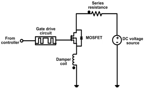
The control system set up for the semi-active suspension system is shown in Fig. 5. The control elements consist of the following parts: (i) accelerator sensors 1 and 3, (ii) displacement sensor 2, (iii) A/D and D/A converters, (iv) signal conditioners, and (v) voltage to current converter (V/A) unit. The circuit schematic of the V/A unit is shown in Fig. 6. It is designed to adjust the input current to the electromagnetic coil of the MR damper in such a way as to minimize the suspension displacement of the sprung mass of the quarter car.
Fig. 5. Hardware and software interface setup (USM: unprung mass, SM: sprung mass, sensor 1 and sensor 3 are accelerometer, sensor 2 is displacement meter)
[image:3.612.312.569.425.634.2]Fig. 6. Voltage to current converter circuit.
IV.
I
MPLEMENTATION OFC
ONTROLLER ON THER
EALS
EMI-
ACTIVES
USPENSIONS
YSTEMThe developed PC based controllers using PID, fuzzy logic and hybrid-fuzzy were connected to the semi-active suspension system through the A/D and D/A cards. When the suspension mass (sprung and unsprung) were excited by the shaker, acceleration and displacement data were collected by sensors and then sent to the controller which executed and sent the required output to the MR damper through the voltage to current converter. Depending on controller output, the MR damper changes its damping force to suppress the suspension vibration of the car model.
V.
E
XPERIMENTAL TESTING OFS
EMI-ACTIVES
USPENSIONS
YSTEM OF QUARTER CAR MODELThe objective of the control system is to minimize displacement of the sprung mass under three induced road disturbances, namely random, square and sine-wave signals. These road disturbance signals are generated by the shaker of the semi-active suspension system. If the measured displacement is less or greater than the set point (zero), the controller senses the signal. Consequently, the controller sends a signal to change the damping constant in the MR damper in such a way as to reduce vertical movement and/or suspension of the sprung mass of the car body. Figure 7 shows the fuzzy logic triangular membership functions for the semi-active suspension control system.
[image:4.612.335.556.55.300.2]The triangular membership function are negative big [NB], negative medium [NM], negative small [NS], zero [ZE], positive small [PS], positive medium [PM], positive big [PB] respectively. It is to be noted that displacement y of car body, and difference between sprung mass displacement and unsprung mass displacement y-x are used as fuzzy controller input 1 and input 2, as shown in Figs. 7(a) and 7(b), respectively. In this paper, the scaling for both input 1 and input 2 is set from -8 to +8 with increment of 2 from the lowest value. According to different input conditions, the actuating valve will open from –100% to +100% for smooth control of suspension. The damping force from the MR damper is the fuzzy output membership function as shown in Fig. 7(c).
Fig. 7: Fuzzy triangular membership functions: (a) input 1: car body displacement y, (b) input 2: displacement between unsprung and sprung masses, y-x and (c) output- damping force.
It is to be noted that the output is set from -100 to 100% with increment of 25% from the lowest value. Figure 8 shows the block diagram representation of the fuzzy logic control system.
VI.
H
YBRIDF
UZZY CONTROLLER FOR SUSPENSION SYSTEM Figure 9 shows the block diagram representation of the hybrid fuzzy logic system. The car suspension system being quite coupled it is difficult to control it with conventional methods. The PID controller may be efficient in linear system, but the fuzzy controller is able to work better in uncertain and nonlinear conditions. The performances of both controllers were checked in the car suspension system. Although simple fuzzy logic controller is overall better than a PID controller, for certain type of disturbances, the former adversely affects the performance of the suspension system. For such cases, the fuzzy logic controller (FLC) and PID controller are combined together as the hybrid controller to get better performances of suspension systems.The results of laboratory testing of the MR damper system on the quarter-car apparatus are presented for each of three disturbance conditions using fuzzy logic and hybrid controllers. The experimental acceleration performance results of the fuzzy controller for the sinusoidal, square and random disturbances are given in figures (10) – (12), respectively. The experimental displacement performance results of the hybrid controller for the sinusoidal, square and random disturbances are given in figures (13) – (15), respectively.
for road conditions with sinusoidal disturbances for the PID, fuzzy, and hybrid controllers.
[image:5.612.45.300.260.416.2] [image:5.612.327.554.453.683.2]Fig. 8 Block diagram representation of the fuzzy logic control system.
Fig. 9 Block diagram representation of the hybrid-fuzzy logic control system.
It is to be noted that the reduction percentage is the decrease of the disturbance amplitude with an active controller as compared to that with any conventional controller. Similarly, Table-III and Table-IV contain the RMS and IAE values of car body displacement for road conditions with square wave and random disturbances, respectively for the PID, fuzzy and hybrid controllers.
From these results it can be seen that fuzzy logic based controller shows better performance compared to those obtained from the PID controller in all cases. However, in order to incorporate the advantages of both types of controllers, a hybrid control system is used for the control of the suspension system. The performances of the hybrid controller in this semi active suspension control system have been again checked by changing the road disturbances with constant set point of displacement at zero. In this work, three types of road disturbances are used, namely sinusoidal, square wave and random disturbances. Results of the step responses for the hybrid controller are shown in Figs. 13 to 15. Furthermore, the detailed experimental performance results are summarized in Tables II-IV. For the system with the sinusoidal road disturbances in Table-II, it can be seen that the hybrid controllers rejected more than 92.7% of the amplitude, which
is better than 91.5% rejection for the fuzzy logic controller, while the PID controller rejected 29.1% of the disturbance amplitude. For the system with the square wave road disturbances in Table-III, it can be seen that the hybrid controller rejected more than 94.3% of the amplitude which is better than 92.1% rejection for the fuzzy controller, while the PID only rejected 26.2% of the disturbance amplitude. For the system with the random road disturbances in Table-IV, it can be seen that the fuzzy and hybrid controllers rejected more than 91.1 % of the amplitude, again slightly better than 90.3% the fuzzy controller, while the PID controller rejected 28.1% only of the disturbance amplitude.
TABLE-II
EXPERIMENTAL PERFORMANCE RESULTS OF SEMI ACTIVE SUSPENSION SYSTEM WITH SINUSOIDAL ROAD DISTURBANCES
TABLE-III
EXPERIMENTAL PERFORMANCE RESULTS OF SEMI ACTIVE SUSPENSION SYSTEM WITH SQUARE WAVE ROAD
DISTURBANCES
Controller MSE % Reduction IAE PID 0.6029 26.2 62.356 Fuzzy Logic 0.0647 92.1 5.84
Hybrid 0.0466 94.3 4.54
TABLE-IV
EXPERIMENTAL PERFORMANCE RESULTS OF SEMI ACTIVE SUSPENSION SYSTEM WITH RANDOM ROAD DISTURBANCES
Controller MSE % Reduction IAE PID 0.5391 28.12 58.144 Fuzzy Logic 0.0726 90.33 6.94
Hybrid 0.0664 91.15 6.48
Fig. 10. Experimental results (acceleration) of fuzzy controller of semi active suspension system for sine wave input disturbances.
Controller MSE % Reduction IAE PID 0.3545 29.1 43.128 Fuzzy Logic 0.0425 91.5 5.25
Fig. 11. Experimental results (acceleration) of fuzzy controller of semi active suspension system for square wave input disturbances.
Fig. 12. Experimental results (acceleration) of fuzzy controller of semi active suspension system with random input disturbances.
[image:6.612.56.287.253.414.2]Fig. 13. Experimental results (displacement) of hybrid controller of semi active suspension system with sine wave disturbances.
Fig. 14. Experimental results (displacement) of hybrid controller of semi active suspension system with square wave disturbances.
Fig. 15. Experimental results (displacement) of hybrid controller of semi active suspension system with random disturbances.
VII.
S
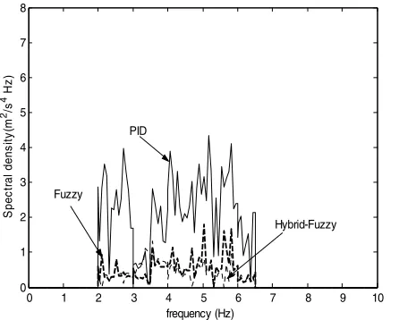
PECTRAL DENSITY ANALYSISThe spectral density is a general concept applied to a signal which may have physical dimensions such as power per Hz, or energy per Hz. Suspension measurements from a spectrum analyzer are often used to formulate the shape of the random test spectrum for a general class of hardware accessories. The key factor in this form of measurement is the way in which the suspension spectrum is actually calculated. In order to achieve a valid spectrum analysis of such suspension sources, many instantaneous signal measurements (samples) made over time must be combined using some kind of spectrum averaging method to produce a statistical approximation of the suspension spectrum by way of power spectral density (PSD) measurement. As an inherent part of the spectrum measurement process itself, infrequently occurring suspension events are discounted in terms of their contribution to the overall measured spectrum. Suspension specifications are usually expressed in terms of peak acceleration for sinusoidal disturbances and rms acceleration for random disturbances. Most suspension systems will have an apparent lower force capability for random disturbances.
time (sec)
0 5 10 15 20 25 30 35 40 -6
-4 -2 0 2 4
6 uncontrolled
controlled
Di
sp
la
ce
me
nt
(c
[image:6.612.313.537.266.425.2] [image:6.612.64.292.446.598.2]The experimental performances of different controllers were compared in the previous section. Some more statistical comparisons of the experimental performances of the semi active suspension are included in this section. The spectral power density is computed from the time responses of the acceleration for the car body semi active suspension system obtained by the different controllers. Figures (16) – (18) show the spectral density of a car body with sine wave, square wave and random input road disturbances, respectively. The robustness of fuzzy and hybrid controllers were examined by changing the road disturbances and it has been observed that fuzzy logic and hybrid controllers decrease the value of spectral density of the disturbance rejection in greater magnitude as compared to those by the PID controller, confirming their superior behaviors over those of the conventional controller. It is to be noted that the power spectral density of the experimental responses is quite close for the fuzzy logic and hybrid controllers for all disturbance cases, as shown by dark lines in Figs. (16) – (18).
0 1 2 3 4 5 6 7 8 9 10
0 1 2 3 4 5 6 7 8 frequency (Hz) S pec tr al dens it y (m 2/s 4 Hz
)
PID
[image:7.612.328.540.60.228.2]Hybrid-Fuzzy Fuzzy
Fig. 16. Spectral density of the acceleration of the car body for sine wave disturbances (4.5 Hz bandwidth).
0 1 2 3 4 5 6 7 8 9 10
0 1 2 3 4 5 6 7 8 frequency (Hz) S pec tr al dens it y (m 2/s 4 Hz
)
PID
Hybrid-Fuzzy Fuzzy
Fig. 17. Spectral density of the acceleration of the car body for square wave disturbances (4.5 Hz bandwidth).
0 1 2 3 4 5 6 7 8 9 10
0 1 2 3 4 5 6 7 8 frequency(Hz) S pec tr al den s it y (m 2/s 4 Hz
)
PID
[image:7.612.64.283.282.455.2]Hybrid -Fuzzy Fuzzy
Fig. 18. Spectral density of the acceleration of the car body for random disturbances (4.5 Hz bandwidth).
It is to be noted that the percentage reduction is the decrease of the disturbance amplitude with an intelligent controller as compared to that without any conventional controller.
VIII.
C
ONCLUSIONThis paper has presented the experimental investigation of the PID, fuzzy logic and hybrid controllers to control the suspension vibrations of an automobile. The semi-active suspension system model uses the magneto rheological damper, which utilizes the magneto rheological fluids to promote adjustable damping effects. The results presented in this paper established that this novel semi-active magneto rheological suspension system can be effectively used to control the suspension of a passenger vehicle with improved ride comfort and steering stability using new hybrid controllers.
REFERENCES
[1] M. Ahmadian and C. Pare, “A Quarter-Car Experimental Analysis of Alternative Semi active Control Methods,” Journal of Intelligent
Material Systems and Structures, vol. 11, no. 8, pp. 604-612, 2000.
[2] A Giua, C. Seatzu, and G. Usai, “Semi active Suspension Design With an Optimal Gain Switching Target,” Vehicle System Dynamics, vol. 31, pp. 213–232, 1999.
[3] V. Roberti, B. Ouyahia, and A. Devallet, “Oleo pneumatic Suspension With Preview Semi-Active Control Law,” in Proc. Int. Conf. MV2,
Active Control in Mechanical Engineering (Lyon, France), vol. 1, pp.
121-131, June 1993.
[4] T.G. Lazareva and I.G.Shitik, "Magnetic and MR Properties of Flowable Compositions Based Oxides," Proceedings of the Society for Optical Engineering, Vol. 3040, pp. 185-189, March 1997.
[5] O. Ashour, C.A. Rogers, and W. Kordonsky, "MR Fluids :Materials, Characterization, and Devices," Journal of Intelligent Material Systems and Structures, vol. 7, pp. 123-130, 1996.
[6] O. Ashour, D. Kinder, V. Giurgiutiu, and C. Rogers, "Manufacturing and Characterization of MR Fluids”, in Proceedings of the Society for
Optical Engineering, pp. 74-184, May 1997
[7] J. D Carlson, D. M. Catanzarite, and K. A. S. Clair, "Commercial MR Fluid Devices," International Journal of Modern Physics B, vol. 10, no. 23-24, pp. 2857-2865, 1999.
[8] R. Bolter and H Janocha, "Design Rules for MR Fluid Actuators in Different Working Modes," in Proceedings of the Society for Optical
[image:7.612.62.285.493.672.2][9] W. Kordonsky, "Elements and Devices Based on MR Effect," Journal of
Intelligent Materials, Systems and Structures, vol. 4, pp. 65-69, January
1996.
[10] W. H. Herschel and R. Bulkley, “Model for time dependent behavior of fluids”, in Proc. American Society of Testing Materials, vol. 26, pp. 621-628, 1962
[11] K. J Kitching., D. J. Cole and D. Cebon, “Performance of Semi-Active Damper for Heavy Vehicles,” ASME Journal of Dynamic Systems
Measurement and Control, vol. 122, pp. 498-506, 2000.
[12] D. E. Ivers and Miller, L. R., “Experimental Comparison of Passive, Semi-active On/Off, and Semi-Active Continuous Suspensions”, SAE
Technical Paper Series, 892484, 1989.
[13] Spencer Jr., B. F., Dyke, S. J., Sain, M. K. and Carlson, J. D., “Idealized Model of a Magneto rheological Damper,” in Proc. of the 12th Conf. on
Analysis and Computation, ASCE, Chicago, Illinois, 1996 pp. 361–370.
[14] Spencer Jr., B. F., Dyke, S. J., Sain, M. K., and Carlson, J.D., “Phenomenological Model for Magneto rheological Dampers,” J. Engrg.
Mech., vol. 123, no. 3, pp. 230-238. February 1996.
[15] M. M Rashid., M. A. Hussain, N. A. Rahim, “Electronic controller for a non-linear Quarter car semi- active suspension system,” Engineering transactions, A research publication of Mahanakorn University of
Technology, Thailand, vol.4, pp 71-79., July-December 2001.
[16] M. M Rashid, M. A. Hussain, and N. A. Rahim. “Electronic Controller For A Non-Linear Quarter Car Active Suspension System,” International
Journal of Vehicle Autonomous Systems Inter Science, no IJVAS-RSH
2006.
[17] M. M. Rashid, “Design and Implementation of Fuzzy based Controllers for Quarter Car Suspension System”, PhD thesis, University of Malaya, 2007.
[18] T. Yoshimura, and A. Takagi, “Pneumatic active suspension system for a one-wheel car model using fuzzy reasoning and a disturbance observer,”
Journal of Zhejiang University SCIENCE, vol. 5, no. 5, pp. 1060-1068,