© 2016, IRJET ISO 9001:2008 Certified Journal
Page 438
An Efficient Hybrid System for Speed Control of Brushless DC Motor
Sunil Kumar
1, Ajay Kumar
21
M.Tech Scholar, Electrical Engineering Department, BUEST Baddi, Himachal Pradesh, India
2Associate Professor, Electrical Engineering Department, BUEST Baddi, Himachal Pradesh, India
---***---Abstract -
The conventional control techniques cannotfulfill the most important needs to optimize dynamic systems, electronic circuits, and industrial processes. Brushless DC motors (BLDC) find wide applications in industries due to their high power density and ease of control. These motors are generally controlled using a three phase power semiconductor bridge. For starting and providing proper commutation sequence to turn on the power devices in the inverter bridge the rotor position sensors are required. Based on the rotor position, the power devices are commutated sequentially every 60 degrees. To achieve desired level of performance the motor requires suitable speed controllers. In case of motors, usually speed control is achieved by using Proportional (P), Proportional integral (PI), PID & fuzzy logic (FL) controller. According to new proposed approach speed control of BLDC motor drive and analysis using hybrid PID-fuzzy logic controller to carry off the weakness of fuzzy logic controller ( Steady-state error ) and PID controller( Overshoots, Undershoots). The proposed hybrid PID-fuzzy logic controller is evaluated via computer simulation using MATLAB simulator.
Key Words: Brushless DC Motor (BLDC), Proportional Integral (PI), Fuzzy Logic Controller (FLC), MATLAB.
1. INTRODUCTION
Brushless dc (BLDC) motors are preferred as small horsepower control motors due to their high efficiency, silent operation, compact volume, long operating life, high speed response, high output power, reliability, and low maintenance. However, the problems are encountered in these motor for variable speed operation. Over last decades,
continuing technology development in power
semiconductors, microprocessors, adjustable speed drivers control schemes and permanent-magnet brushless electric motor production have been combined to enable reliable, cost-effective solution for a broad range of adjustable speed applications. Household appliances are expected to be one of fastest-growing end-product market for electronic motor drivers over the next five years. The major appliances include clothes washers, room air conditioners, refrigerators, vacuum cleaners, freezers, etc. Household appliance have traditionally relied on historical classic electric motor technologies such as single phase AC induction, including split phase, capacitor-start, capacitor–
run types and universal motor. These classic motors typically are operated at constant-speed directly from main AC power without considering the efficiency. Consumers now demand for lower energy costs, better performance, reduced acoustic noise, and more convenience features. Those traditional technologies cannot provide the solutions.
2. BLDC Motor Applications
BLDC motors find applications in every segment of the market. Some of the applications are described below: i) Consumer: PC cooling fans, washing machine, vacuum cleaner, air conditioner, refrigerator, toys.
ii) Medical: artificial heart, microscopes, centrifuges, dental surgical tools, organ transport pump system.
iii) Automobile: automotive applications, electric and hybrid vehicle etc.
We can categorize the BLDC motor control into three major types such as
a) Constant load b) Varying loads
c) Positioning applications
a)
Constant Loads
For single-speed applications, induction motors are more suitable, but if the speed has to be maintained with the variation in load, then because of the flat speed-torque curve of BLDC motor, BLDC motors are a good fit for such applications.
b)
Varying Loads
BLDC motors become a more suitable fit for such applications because variable speed induction motors will also need an additional controller, thus adding to system cost.
c)
Positioning Applications
© 2016, IRJET ISO 9001:2008 Certified Journal
Page 439
3. BLDC Motor Drive control scheme
[image:2.595.40.277.191.490.2]
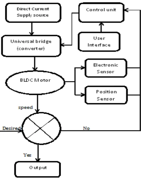
Brushless DC motor known as permanent magnet synchronous motor or may be described as electronically commuted motor which do not have brushes, which means their rotor and stator runs at same frequency that are powered with direct current (DC) inverter/switching power supply, which is build up by using a universal bridge.
Figure -1: Block diagram of BL DC Motor Control scheme
The basic block diagram of BLDC Motor control consist power converter, permanent magnet- synchronous machine (PMSM) sensors, and control algorithm. Three phase inverter transforms power from the source to the PMSM which in turn converts electrical energy to mechanical energy. BLDC motor has rotor position sensors controlled by the command signals, the command signal may be classified as torque, voltage, and speed command and so on. The type of the BLDC motor is determined by the structure of the control algorithms due to which there are two main types voltage source and current source based drives. Permanent magnet synchronous machine with either sinusoidal or non-sinusoidal back-emf waveforms is used by both voltage source and current source based drive. The speed control is obtained by using either PI controller or by using Fuzzy Logic controller.
[image:2.595.310.559.219.414.2]4. PI Speed Control Of BLDC Motor
Figure 2 describes the basic building blocks of the PMBLDC Motor drive. The drive consists of speed controller, reference current generator, PWM current controller, position sensor, the motor and IGBT based current controlled voltage source
inverter (CC-VSI). The speed of the motor is compared with its reference value and the speed error is processed in proportional integral (PI) speed controller.
Is compared with the reference speed and the resulting error is estimated at the nth sampling instant as.
Where the gains of PI are speeds controllers.
Figure-2: PI Speed Controller of the BLDCM Drive.
Following Characteristics of PID controller are given as.
In this P accounts for present value of error, I accounts for past value of error, D accounts for future value of error. Some application may require only one or two terms to provide the appropriate system control. This is achieved by setting the other parameter to zero. A PID controller will be called as a PI, PD, P & I controller in the absence of respective control actions. These are no accurate but each depends upon each other (Kp, Ki, Kd) changing one of them can change the effect of other two.
5. Methodology
According to new proposed approach speed control of BLDC motor drive and analysis using hybrid PID- fuzzy logic controller. There are following steps as follow as:
© 2016, IRJET ISO 9001:2008 Certified Journal
Page 440
Step 2: Apply PI based controller for BLDC motor.
Step 3: Select input as ruler membership function.
Step 4: Generate number of fuzzy ruler for PI based
controller.
Step 5: Introduce fuzzy ruler fuzzification and apply for control operation.
Step 6: Calculate Impulse Response, Amplitude Response
and Speed Fluctuation.
6. Fuzzy Logic Control of BLDC Motor
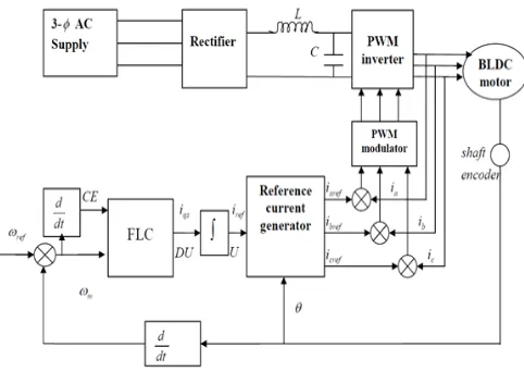
[image:3.595.307.557.75.250.2]The fuzzy logic controller was applied to the speed loop by replacing the classical polarization index (PI) controller. The fuzzy logic controlled BDCM drive system block diagram is shown in Figure 3.
Figure-3: Fuzzy speed control diagram of BLDC motor.
7. Simulated Results
In this section, the proposed algorithm is evaluated via computer simulation using MATLAB simulator. MATLAB stands for MATRIX LABORATORY. It is primarily a tool for matrix computations. MATLAB is a high-level language whose basic data type is matrix that does not requiring dimensioning. There is no compilation and linking as is done in high level languages, such as C. MATLAB has a rich set of plotting capabilities. The graphics are also integrated in MATLAB. Since MATLAB is also a programming environment, a user can extend the functional capabilities of MATLAB by writing new modules. MATLAB has a large collection of toolboxes in a variety of domains. For example communication systems, signal processing, image processing etc. The toolboxes consist of functions that can be used to perform computations in a specific domain. All simulation results are obtained by using fuzzy logic controller, PI controller and hybrid fuzzy logic controller. Figure 4 show line-line voltage variable and stator current.
Figure-4: Input Line-Line Voltage variable and stator
[image:3.595.43.284.267.438.2]current.
[image:3.595.308.556.299.458.2]Figure 5 show output line-line voltage of BLDC control.
Figure-5: Output Line-Line Voltage for BLDC motor control
Figure 6 show emf variation in proposed model.
Figure-6: Proposed model with emf error variation.
[image:3.595.310.559.485.642.2]© 2016, IRJET ISO 9001:2008 Certified Journal
Page 441
[image:4.595.37.293.92.283.2]Figure-7: Hybrid based error variation in speed
Figure 8 show current variation in proposed model.
[image:4.595.306.569.120.325.2]Figure-8: Current variation in proposed model.
Figure 9 show comparison of PID and hybrid on the basis of speed and time.
Figure-9: Comparative analysis of PID and hybrid on the
basis of speed and time.
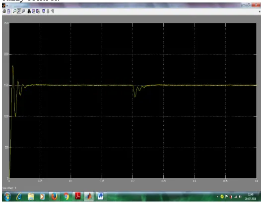
Figure 10 show initial speed variation of BLDC based on fuzzy control.
Figure-10: Initial speed variation of BLDC based on fuzzy
control.
8. Conclusion
A hybrid fuzzy logic controller (HFLC) has been employed for the speed control of BLDC motor drive and analysis of results of the performance of a fuzzy controller is presented. The modeling and simulation of the complete drive system is described. Effectiveness of the model is established by performance prediction over a wide range of operating conditions. A performance comparison between the hybrid fuzzy logic controller and the conventional PI controller has been carried out by simulation runs confirming the validity and superiority of the fuzzy logic controller for implementing the hybrid fuzzy logic controller is adjusted. The performance of the BLDC drive with reference to PI controller, hybrid fuzzy logic controller and fuzzy logic controller experimental verified with conventional controller. Hybrid fuzzy logic speed controller improved the performance of BLDC Drive of the fuzzy logic speed controller. For further extent of the work, new Artificial Intelligence (AI) technique can also be used for multiple control of BLDC motor.
Appendix
Brushless DC motor: 3-phase, 440 volt, 1600 rpm
Parameter: Stator phase resistance=2.875Ώ, Stator phase
[image:4.595.38.265.320.496.2] [image:4.595.37.290.542.728.2]© 2016, IRJET ISO 9001:2008 Certified Journal
Page 442
REFERENCES
[1] Thomas M Jahns, “Torque Production in
Permanent-Magnet Synchronous Motor Drives with Rectangular Current Excitation,” IEEE Transactions on Industry Applications, Vol. IA-20, Issue 04, July 1984, pp.803-813.
[2] Carlos, Jean Hector and Michel Lajoie Mazenc, “Study and
Implementation of Hysteresis Controlled Inverter on a Permanent Magnet Synchronous Machine,” IEEE Transactions on Industry Applications, Vol. IA-21, Issue 02, Mar 1985, pp.408-413.
[3] Eike Richter, Timothy J E Miler and Thomas L Hudson, “The Ferrite Permanent Magnet AC Motor-A Technical and Economical Assessment,” IEEE Transactions on Industry Applications, Vol. IA-21, Issue 03, May 1985, pp.644-650.
[4] P Pillay and R Krishnan, “Selection Criteria for Servo
Motor Drives,” IEEE Transactions on Industry Applications, Vol. IA-23, Issue 02, Mar 1987, pp.270-275.
[5] Congzhao Cai, Hui Zhang, Jinhong Liu, Yongjun Gao, “Modeling and Simulation of BLDC motor in Electric Power Steering,” IEEE Transactions on Industry App2010 Asia-Pacific Power and Energy Engineering Conference, 28-31 March 2010.
[6] Radu Duma, Petru Dobra, Mirela Dobra, Ioan Valentin Sita and Thomas M Jahns, “Low cost embedded solution for BLDC motor control,” System Theory, Control, and Computing (ICSTCC), 2011 15th International Conference, 14-16 Oct. 2011.
[7] Yasuhiro Komatsu, Syed Abdul Kadir Zawawi, Hirotaka Ito and Yoshihiko Arakins, “The study of unidirectional energized BLDC motor for E-type iron core,” Electrical Machines and Systems (ICEMS), 2011 International Conference, 20-23 Aug. 2011.
[8] Seyed Mohammad Hossein Mousavi,Seyed Sajjad Salehi Ghaleh Sefid and Seyed Ebrahim Salehi Ghaleh Sefid “Simulation of a new multiphase BLDC motor drive,” 2012 IEEE International Conference on Power Electronics, Drives and Energy Systems (PEDES), 16-19 Dec. 2012.
[9] Meagan Mathew, M. Jayakumar, “Isolating faults in BLDC
motors using discrete square root filtering and Bayes Classification,” 2012 Annual IEEE India Conference (INDICON), 7-9 Dec. 2012.
[10] Muhammad Nizam, Agus Mujianto, Hery Triwaloyo and Inayati, “Modelling on BLDC motor performance using artificial neural network (ANN),” Rural Information & Communication Technology and Electric-Vehicle Technology (rICT & ICeV-T), 2013 Joint International Conference, 26-28 Nov. 2013.
[11] Tashakori and M. Ektesabi, “Torque A simple fault
tolerant control system for Hall Effect sensors failure of BLDC motor,” 2013 IEEE 8th Conference on Industrial Electronics and Applications (ICIEA), 19-21 June 2013.
[12] Ranganth Muthu, M. Senthil Kumaran, L. A. Abishek Rajaraman and P. Ganesh, “Direct Torque Control of matrix converter fed BLDC motor,” 2014 IEEE 6th India International Conference on Power Electronics (IICPE), 8-10 Dec. 2014.
[13] Taywin Nilsakorn, Kaweepoj Woranetsuttikul, Kittapas Pinsuntia, “Harmonic effect on BLDC motor temperature caused by driving system,” Electrical Engineering Congress (IEECON), 2014 International, 19-21 March 2014.
[14] Meenu M M and S. Hariharan, “Position sensorless control
of BLDC motor in continuous positive airway pressure device,” 2015 International Conference on Control Communication & Computing India (ICCC), 19-21 Nov. 2015.
[15] Durmus Uygun, Selim Solmaz, Altug Turan, Serife Tozan Ruzgar, “A new topology for dual rotor/stator BLDC motors applied to marine thrusters,” 2015 IEEE 5th International Conference on Power Engineering, Energy and Electrical Drives (POWERENG), 11-13 May 2015.
[16] Abolfazl Halvaei, Hassan Moghbeli and Ehsan Boloor Kashani, “A low-cost sensorless BLDC motor drive using one-cycle current control strategy,” 2014 22nd Iranian Conference on Electrical Engineering (ICEE), 20-22 May 2015.