© 2016, IRJET ISO 9001:2008 Certified Journal Page 1902
SIMULATION AND ANALYSIS OF SHUNT ACTIVE POWER FILTER
Akashkumar Chavada, pushprajsinh Thakor
2, Bipinkumar Nanecha
31
PG Scholar, Dept. Electrical Engineering, TITS Modasa, Gujarat, India
2PG Scholar, Dept. Electrical Engineering, TITS Modasa, Gujarat, India
3
Assi.professor, Dept. Electrical Engineering, TITS Modasa, Gujarat, India
---***---Abstract-This paper proposes a fuzzy logic controller fordc link voltage regulation to enhance the performance of widely used active power filter control strategies, namely, p-q method. The dynamic performance of the systems are Evaluated under different supply conditions and compared with the performances of the working with PI controller. The effectiveness of the fuzzy logic controller, in terms of total harmonic distortion (THD) in supply current and regulation of dc-link voltage is validated.
Keyword- Shunt APF, p-q method, dc-link voltage regulation, PI controller, Fuzzy logic controller.
I INTRODUCTION
Since the past few decades, there has been intensive increase in the use of power converters and switching devices, various nonlinear loads and equipment’s which draw highly non-linear current from the source and thereby inject harmonics in the system. These harmonics are perilous and greatly pollute the power system. They degrade power quality by increasing total harmonic distortion (THD) and reactive power consumption and also by causing poor power factor, voltage flicker, bad voltage regulation, voltage sags and swells, unbalanced load etc.[1]-[3]. Harmonics also cause electromagnetic interference (EMI) in communication network present within certain proximity. Issues pertaining to power quality are increasing steeply, therefore, tackling these problem become an indispensable task for maintaining a good power system.
Power filters came up as a viable solution for providing clean-harmonic free power at consumer ends. Conventionally, passive L-C filters were employed for harmonics mitigation and capacitors for power factor improvement. But gradually
they got replaced by active power filters (APFs) because they are associated with certain inherent disadvantages like bulky size, mistuning, instability, resonance with load impedance or utility impedance and lack of flexibility. APFs give dynamic and versatile solution to the problem of power quality.
Research on APF technology boomed up and a large number of control techniques are being proposed and implemented. At present there is an appreciably large number of control methods used for power compensation by APFs.
This paper proposes a new fuzzy logic controller (FLC) for dc-link voltage regulation to enhance the performance of shunt APFs operating with p-q control method.
II SYSTEM CONFIGURATION
[image:1.595.311.561.365.527.2]Fig.1. Shows the system configuration of a power system compensated by shunt connected APF. The APF is a pulse width modulated (PWM) inverter and the non-linear load is composed of a three phase diode rectifier with R-L load. The PWM inverter is an IGBT based voltage source inverter (VSI). The values of system parameters are given in Appendix. The shunt-APF injects a compensating current which is an exact opposite of the distortion produced by the load to the line current, thus, nullifying the distortion. The amount of compensating power injected by the filter is controlled with suitable method to get perfect compensation.
Fig. 1. System configuration of 3-phase compensated system
III. CONTROL ALGORITHMS
© 2016, IRJET ISO 9001:2008 Certified Journal Page 1903 by nonlinear load can be converted by the components of
Concordia into:
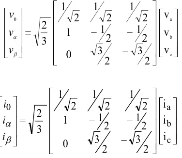
c b a 0v
v
v
2
3
2
3
0
2
1
2
1
1
2
1
2
1
2
1
3
2
v
v
v
c b a 0i
i
i
2
3
2
3
0
2
1
2
1
1
2
1
2
1
2
1
3
2
i
i
i
The instantaneous real and imaginary power can be expressed by the following system:
Lβ Lα α β β α L Li
i
v
v
v
v
q
p
The instantaneous real and imaginary power can be Decomposed into two AC and DC parts. The DC part resulted from the fundamental current and voltage and the AC part resulted from the harmonics [10,14]:
q
q
q
p
p
p
~
*
~
*
The references currents are calculated by the following expression:
q
p
v
-v
v
v
v
v
1
i
i
α β β α 2 β 2 α Cβ CαInverse transforms,
q
p
v
-v
v
v
2
3
2
1
2
3
2
1
0
1
3
2
i
i
i
α β β α Cc Cb CaIV. HYSTERESIS BAND CURRENT TECHNIQUE
Hysteresis band current control does not need any information about the system parameters but has the disadvantage of uncontrolled switching frequency. The instantaneous value of the error can be calculated by subtracting from the identify reference harmonic currents (iref) obtained by using diagram bloc of (p–q theory), and the
injection harmonic currents (iinj) of (SAPF), subtraction
between (iinj) and (iref) , introduced in hysteresis band
[image:2.595.67.255.136.299.2]current to generate the gate pulses [9,15,16], The hysteresis control law is given as fig. .2.
Fig. 2. Hysteresis band current control
IV. CONTROL OF DC VOLTAGE SOURCE OF (SAPF)
The advantage control of DC bus capacitor voltage source of (SAPF) arise suitable transit of supply power necessary added to power active fluctuate. The storage capacity C absorbs the power fluctuations caused by the compensation of the reactive power [17,18]. The normal conditioner, the real power supplied by the source should be equal to the real power demand of the load plus a small power to compensate the losses in the active filter [19]. Thus, the DC bus capacitor voltage can be kept at constant value and confirmed at a reference value. However, in the abnormal conditioner, In the presence of harmonics current, when the load changes, the real power balance between the source and the load will be disturbed. In this case, the real power poured most be compensated by the dc capacitor of inverter constructor of (SAPF). The changes of DC capacitor voltage from its reference most be regulate [19,20]. A fuzzy logic controller is
applied to maintain the constant voltage across the capacitor by minimizing the error between the capacitor voltage and its reference voltage, the block diagram of a control is illustrated by the figure. 4.
© 2016, IRJET ISO 9001:2008 Certified Journal Page 1904 PS(Positive Small), PM(Positive Medium)and PL(Positive
[image:3.595.311.511.122.298.2]Large).Membership functions of the input and output variables are shown in fig. The fuzzy IF-THEN rules formed for controlling the DC voltage are given in Table-
Table I- Fuzzy Rule Base for Voltage Control
Error (e)
Change in error(de)
NL NM NS ZE PS PM PL
NL NL NL NL NL NM NS ZE NM NL NL NL NM NS ZE PS NS NL NL NM NS ZE PS PM ZE NL NM NS ZE PS PM PL PS NM NS ZE PS PM PL PL PM NS ZE PS PM PL PL PL PL NL NM NS ZE PS PM PL
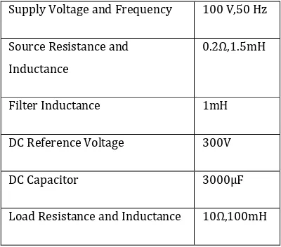
TABLE NO.I MATLAB PARAMETER FOR SIMULATION
Supply Voltage and Frequency 100 V,50 Hz
Source Resistance and Inductance
0.2Ω,1.5mH
Filter Inductance 1mH
DC Reference Voltage 300V
DC Capacitor 3000µF
Load Resistance and Inductance 10Ω,100mH
VII SIMULATION RESULTS
Simulations test is performed to confirm the validity of the proposed system. The (SAPF) was designed to compensate harmonics caused by nonlinear loads, the simulated results were obtained by using hysteresis band current and fuzzy logic controller was examined through Matlab/Simulink. The nonlinear load is a three-phase full-bridge diode rectifier supplying a RL load. The hysteresis band current is used to determine the switching time pulses of SAPF, the (p–q theory) is used to determine the three phases reference harmonic currents and the fuzzy logic controller is used to regulate DC bus capacitor voltage source of (SAPF). All spectrum harmonic analysis presented, should be limited in terms of total distortion harmonic (THD), and compared to the limit harmonic imposed by international standards [2].
Fig.4 show waveforms of the three phase source current currents and its spectrum harmonics analysis, without (SAPF), the THD is 20.45% before harmonic compensation. In this case, that is far the limit of the harmonic standard
[2]. The reference harmonic currents identify using p–q
[image:3.595.39.557.208.772.2]© 2016, IRJET ISO 9001:2008 Certified Journal Page 1905 Fig 3 Waveform of Supply Voltage, Supply Current and
Load Current without Filter.
The comparison between injection (iinj ) and reference
(iref ) currents of (SAPF ) shown as fig. 9. We can be seen a
[image:4.595.305.557.67.200.2]better conformation and superposition with excellent properties. The fig.5,6, show waveforms of the three phase source current currents and its spectrum harmonics analysis, The THD decreases to at 2.54% using PI Controller and 1.61% using fuzzy controller before harmonic compensation, which is within the limit of the harmonic standard [2].
[image:4.595.38.273.290.417.2]Fig 4. Waveform of Supply Current, Load Current and Filter Current with Filter using PI Controller
[image:4.595.51.273.448.577.2]Fig 5. Waveform of Supply Current, Load Current and Filter Current with Filter using Fuzzy Controller.
Fig 6. Supply Current THD with Filter using PI Controller
Fig 7. Supply Current THD with Filter using Fuzzy Controller
VIII CONCLUSION
In this report the three phase three wire shunt active filter based on the instantaneous real and reactive power control strategy with PI controller have been analysed. It is found from the simulation results that shunt active power filter improves power quality of system by eliminating harmonics of non-linear load. The dc bus voltage has been maintained constant equal to the reference voltage by all PI and Fuzzy controllers. It has been found that these robust and nonlinear control proves to be better than conventional control. The THD of the source current is below 5% according to simulation result and it is in permissible limit of IEEE standard.
REFERENCE:
[1] Roger c .dugan .Mark F. McGranaghan, Surya Santoso, H. wayne Beaty, “Electrical power system quality”, Tata mc grawhill., edition.2, pp. 01-132, August 2004.
[2] Almoataz Y. bdelaziz, Said F .Mekhamer, Sherif M.Ismael, “Technical Consideration in Mitigation Techniques Applied to the Industrial Electrical Power System”22nd International Conference On Electricity Distribution. June 2013
[3] Sumita D Chakrabortty, Naimesh Zaveri, Darshan Rayajiwala, “Analysis of various control techniques of Shunt Active Filter’’ IEEE trans.pp.1-6,March-2014.
[4] S.Kothuru, A.Naidu, Suresh Y., J. Kotturu, “Investigat-ion on Shunt active Filter with P-Q Theory” IEEE Trans.pp.445-449, March-2013.
[5] N. Patnaik, Anup Kumar Panda, “Comparative Analysis on a Shunt Active Power Filter with different Control Strategies for Composite loads” IEEE Trans.pp.1-6,October-2014.
[6] Che Yanbo, Wu Diyun, Wang Chenshan, Ai Lin, “Simulation and Experimental Research on Shunt Active Power Filter” IEEE Trans.pp.1-4, March-2009.
[image:4.595.37.276.621.716.2]© 2016, IRJET ISO 9001:2008 Certified Journal Page 1906 Power Filter for Harmonic Reduction” IEEE
Trans.pp.1377-1383, Oct-Nov-2014
[8] Alejandro Orozco Montes, Gustavo, “Instantaneous p-q Theory for harmonic compensation via Shunt Active Power Filter” IEEE Trans pp.1-4, July-2013
[9] S Kotharu, J kotturu, Kumar reddy, “Reduction of Harmonics In 3-Phase, 3-Wire System by the Use of Shunt Active Filter” International Conference on Circuits, Power and Computing Technologies, IEEE Trans.pp.7 – 12, March 2014.
[10] Sushil Karvekar, Aditi Kumbhojkar,“ Comparison Of Different Methods Of Reference Current Generation For Shunt Active Power Filter Under Balanced And Unbalanced Load Condition” international conference on circuits, power and computing Technologies,pp.430-434, 2013
[11] Vikash Anand, Dr. S.K.Srivastava, “Performance Investigation of Shunt Active Power Filter Using Hysteresis Current Control Method” International Journal of Engineering research & Technology (IJERT), pp.1-4, June-2012.
[12] Pradeep Anjana, Vikas Gupta, Harpal Tiwari,“ Reducing harmonics in micro grid distribution system using apf with pi controller, IEEE Trans,pp.1-6,April-2014.
[13] Nishant Patnaik, Anup Kumar Panda, “Comparative analysis on a shunt active power filter with different control strategies for composite loads”, IEEE Trans,pp.1-5,Oct-2014
[14] Roger c .dugan .Mark F. McGranaghan, Surya Santoso, H. wayne Beaty, “Electrical power system quality”, Tata mc grawhill., edition.2, pp. 01-132, August 2004.
[15] Faiza Kaddari, Youcef Mihoub, Ahmed Safa,” Comparison of two compensation control strategies for shunt active power filter”, IEEEE Trans,pp.384-389,Oct-2014
[16] Azuki Abdul Salam,Nik Azran Ab Hadi, “Fuzzy Logic Controller for Shunt Active Power Filter”, IEEE Trans,pp.256-259,August-2014.
[17] K.K.Pedapenki, S.P.Gupta, M.Pathak, “Comparison of PI & Fuzzy Logic Controller for Shunt Active Power Filter”, IEEE Trans.,pp.42-47,Dec.-2013.
[18] Anil M.Gore, Dagadu S. More, “Performance Investigation of Shunt Actie Power Filter with PI and Fuzzy Controllers”, IEEE Trans,pp.1159-1164,Aug-2013.
[19] Sakshi Bangia, P.R.Sharma, Maneesha Garg, “Comparison of Artificial Intelligence Techniques for The Enhancement of Power Quality”, IEEE Trans,pp.537-541,Feb-2013.