© 2016, IRJET ISO 9001:2008 Certified Journal Page 1656
Earthquake Behavior of RCC Building for Various Shear Wall
Configurations
Tejas Shaha
1, Anirudhha Banhatti
21
Department of Civil Engineering, G. H. Raisoni College of Engineering and Management, Wagholi, Pune.
2Professor, Department of Civil Engineering, G. H. Raisoni College of Engineering and Management, Wagholi, Pune.
---***---Abstract -
A large portion of India is susceptible to damaging levels of seismic hazards. Hence, the response of structures under wind and earthquake effects are very important area where the researchers should concentrate and bring out effective disaster mitigating techniques so that the structures remain in function. In case of low-rise buildings effects of earthquake and wind are not so important during designing. But as height of buildings goes on increasing, the effects of both earthquakes and wind are increases. Therefore, it is essential to consider effects of lateral loads induced from earthquakes and wind. The effects can be found out by analyzing buildings for earthquake and wind forces. In present study, we can study G+20 Multi-storey building which is situated in zone IV. Multi-storey building without RCC shear wall and same model with RCC shear wall is consider and the effect due to change in position of RCC shear wall is consider, comparative study has been carried out. Software ETABS 9.7 is used for the analysis and design of both cases. The result parameters such as displacement, base shear, story drift are compared for models carrying RCC shear walls with different position and without shear wall model also wind load effect is observed By providing shear walls in proper position can be minimized effect and damages due to earthquake and winds.Key Words: ETABS 9.7, Shear wall, RCC, Base Shear, Time Period
1. INTRODUCTION
Generally shear wall can be defined as structural vertical member that is able to resist combination of shear, moment and axial load induced by lateral load and gravity load transfer to the wall from other structural member. Reinforced concrete walls, which include lift wells or shear walls, are the usual requirements of multi-storey buildings. Design by coinciding centroid and mass center of the building is the ideal for a Structure. An introduction of shear wall represents a structurally efficient solution to stiffen a building structural system because the main function of a shear wall is to increase the rigidity for lateral load resistance. In modern tall buildings, shear walls are commonly used as a vertical structural element for resisting the lateral loads that may be induced by the effect of wind and earthquakes which cause the failure of structure as
shown in figure Shear walls of varying cross sections i.e. rectangular shapes to more irregular cores such as channel, T, L, barbell shape, box etc. can be used.
Fig -1: Details of Shear wall
[image:1.595.318.549.278.743.2] [image:1.595.320.549.285.489.2]© 2016, IRJET ISO 9001:2008 Certified Journal Page 1657 Provision of walls helps to divide an enclose space, whereas
of cores to contain and convey services such as elevator. Wall openings are inevitably required for windows in external walls and for doors or corridors in inner walls or in lift cores.
2. METHODOLOGY
Modeling of structure is done in commercial software ETABS 9.7 which is based on finite element method. The space frame G+20 model is prepared. Column base are assigned as fixed support. Column and beam are model as line element, slab and shear wall are area section but slab are assigned as membrane and shear wall assigned as shell element.
[image:2.595.308.559.99.231.2]A multistory building is taken into consideration. Building having a RCC shear wall throughout the height of building. Details of multistory frame building are as follows Storey of building : G+20 storey, Frame, Floor to floor height : 3.5 m Seismic zone : Zone IV ,Soil type : Medium soil (Type II) Shear wall : 230 mm thick and Beam in X and Y-direction : 230 x 650 mm, Column: 600X600 mm, span between column : 5 m. RCC slab: 200 mm thick and load cases used for analysis
Table -1: Load Cases
SR.NO Load cases Load
1. Dead load Gravity
2. Live load Gravity
3. Super imposed DL Gravity
4. EQX IS1893:2002
5. EQY IS1893:2002
6. WINDX IS875:1987
7. WINDY IS875:1987
8. RES-X IS1893:2002
9. RES-Y IS1893:2002
Load combination used as per IS1893 (Part 1):2002 clause6.3.1.2, the following load cases have to be consider for analysis
a) 1.5 (DL + IL) b) 1.2 (DL ± IL ± EL) c) 1.5 (DL ± EL) d) 0.9 DL ± 1.5 EL
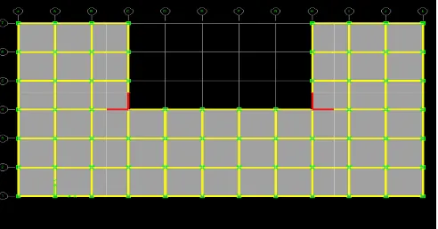
Fig -3
: Plan of Building Model 1Fig -4: Plan of Building with Shear Wall Model 2
Fig -5: Plan of Building with Shear Wall Model 3
[image:2.595.309.561.271.385.2] [image:2.595.310.556.418.547.2] [image:2.595.309.554.584.706.2]© 2016, IRJET ISO 9001:2008 Certified Journal Page 1658
3. SEISMIC ANALYSIS OF BUILDING
3.1 Equivalent Static Analysis
Seismic analysis of most of the structures are still carried out on the basis of lateral (horizontal) force assumed to be equivalent to the actual (dynamic) loading. The base shear which is the total horizontal force on the structure is calculated on the basis of structure mass and fundamental period of vibration and corresponding mode shape. The base shear is distributed along the height of structures in terms of lateral forces according to Code formula. This method is usually conservative for low to medium height buildings with a regular conformation.
3.2 Response Spectrum Analysis
This method is applicable for those structures where modes other than the fundamental one affect significantly the response of the structure. In this method the response of Multi-Degree of freedom (MDOF) system is expressed as the superposition of modal response, each modal response being determined from the spectral analysis of single degree of freedom (SDOF) system, which are then combined to compute the total response. Modal analysis leads to the response history of the structure to a specified ground motion; however, the method is usually used in conjunction with a response spectrum.
These methods give conservative results but have the advantage of being simple and easy to use. It ignores the effect of higher modes and cannot accommodate irregularities in the structure. It is used for checking against moderate earthquakes since the emphasis is on resisting the earthquake loads by virtue of elastic strength rather than inelastic behavior.
4. SHEAR WALL
G+20 multistory building with RCC shear wall at different position in every model and its analysis is done on ETABS 9.7. Description of Structures: The building located in IV seismic zone where Importance factor(I) and Zone factored(Z) considered 1 and 0.24,Response Reduction Factor for SMRF is 5.0. The grade of concrete M20 for Footing, beam, slab, shear wall and for column M25 concrete grade for Steel Fe415 grade used. These are the analysis parameter considered for all models. Live load are consider according to IS code and Wind load as per IS:-875(Part III)- 1987.In that wind speed 50 m/s, K1=1, Where height of building is 73.5 m,Typical floor to floor height is 3.5 m, length of shear wall is taken as 3m and 5m. thickness of shear wall is 230mm.
Fig -7: 3D Model of Building
Fig -8: 3D Model of Shear Wall Building
[image:3.595.306.505.98.259.2]Fig -9: 3D Model of Shear Wall Building
[image:3.595.308.503.288.418.2] [image:3.595.308.504.448.579.2] [image:3.595.307.503.612.742.2]© 2016, IRJET ISO 9001:2008 Certified Journal Page 1659
5. RESULTS
5.1 Story Shear
Chart -1: Story Shear
For G+20 multistorey building without shear wall, base shear obtained from earthquake analysis is 18% less than that obtained from structure with shear wall placed at corners.
5.2 Story Drift
Chart -2: Story Drift
As per IS 1893(part1): 2002 (cl 7.11.1) storey shall not exceed 0.004 times of story height. In this study maximum story height is 3.5m and as per IS recommendation allowable story drift is 16.8mm.
[image:4.595.307.561.377.532.2]5.3 Max Displacement of Building
Table -2: Maximum displacement
Model 1 Model 2 Model 3 Model 4
MAX
22.23 17.27 18.42 19.16
DISPLACEMENT (mm)
The displacement of without shear wall building is more, and it is not feasible for high rise structure. Displacement can be control by using shear wall at exact location.
5.4 Time Period
Table -3: Time period
Period
Mode MODEL 1 MODEL 2 MODEL 3 MODEL 4
1 3.512241 3.066166 3.202468 3.244938
2 3.453767 3.01077 3.177107 3.002906
3 3.255661 2.436189 3.131679 2.705365
4 1.149697 0.944361 1.037301 1.020066
5 1.131352 0.931048 1.015243 0.917782
6 1.071014 0.704196 0.986517 0.82154
7 0.660972 0.501048 0.597548 0.552831
8 0.652074 0.496936 0.558324 0.479949
9 0.623135 0.349629 0.537614 0.423174
10 0.45818 0.324609 0.410304 0.357005
11 0.452427 0.322636 0.371372 0.299792
12 0.432866 0.23036 0.355611 0.259003
Fundamental natural periods T of normal single storey to 20 storey buildings are usually in the range of 0.05-3.00 sec. time period of building is more it means the structural damage of the building is minimum. But Deflection is more, so we can control by using various position of shear wall in structure.
5.5 Displacement for earthquake and wind loading
Chart -3: Maximum displacement
Graph shows Comparison of displacement for earthquake and wind loading. Top storey displacement obtained from earthquake analysis is 8% less than that obtained from wind analysis. As building height increases, effect of wind load as compare to earthquake load is more dominating.
[image:4.595.37.283.384.547.2]© 2016, IRJET ISO 9001:2008 Certified Journal Page 1660
6. CONCLUSIONS
Shear walls are one of the most effective building elements in resisting lateral forces during earthquake as well as winds. By providing shear walls in proper position can be minimized effect and damages due to earthquake and winds.
Stiffness of building increases due to adding shear wall, hence reducing the damage to structure.
Length of shear wall in model no2 is less than model no 4, but behavior of model no2 building is good so it shows position of wall can reduces quantity and cost also.
Top storey displacement obtained from earthquake analysis is 8% less than that obtained from wind analysis.
From the analysis it is observed that maximum deflection in Model 2 is reduced by 23% in the Model 1
REFERENCES
[1] M. V. M. Dr. Suchita Hirde, "Severity of Earthquake Forces against Wind Forces for Multistorey RCC Building " IOSR Journal of Mechanical and Civil Engineering (IOSR-JMCE) pp. 71-75, 2014.
[2] D. K. R. M. R. Ehsan Salimi Firoozabad, Bahador Bagheri, "Effect of Shear Wall Configuration on Seismic Performance of Building " Proc. of International Conference on Advances in Civil Engineering and Association of Civil and Environmental Engineering, 2012.
[3] N. A. P. S. Shyam Bhat M, Asha U Rao, "Earthquake Behaviour Of Buildings With And Without Shear Walls," Journal of Mechanical and Civil Engineering (IOSR-JMCE) 2003.
[4] A. J. C. a. P. J. Moss, "The Effects of Large Displacements on the Earthquake Response of Tall Structures," Senior Lecturer, Department of Civil Engineering, University of Canterbury, Christchurch, New Zealand, p. 4, 1999. [5] IS: 1893(2000,Part 1),“Indian standard criteria for
earthquake Resistance Design of Structure”, bureau of Indian standards, New Delhi.
[6] IS:456(2000),“Indian Standard code of Practice for Plain and Reinforced concrete”, bureau of Indian standard, New Delhi.