2019 International Conference on Information Technology, Electrical and Electronic Engineering (ITEEE 2019) ISBN: 978-1-60595-606-0
FPGA Implementation of Machine Learning Hardware Accelerator for
Mobile Applications of Brain-Computer Interface
Wen-tao SHEN
1,2, Li ZHENG
1and Ming LIU
1,*
1
Institute of Semiconductors, Chinese Academy of Sciences, Beijing 100083, China
2
School of Electronic, Electrical and Communication Engineering, University of Chinese Academy of Sciences, Beijing 100049, China
*Corresponding author
Keywords: Brain-computer interface (BCI), Field programmable gate array (FPGA), QR decomposition (QRD), High level synthesis (HLS), Matrix inversion, Givens rotation (GR).
Abstract. Mobile application of brain-computer interface (BCI) system is of great significance. This paper first analyzes machine learning algorithms commonly used in BCI, and extracts QR decomposition as the core step of algorithm integration to design hardware accelerators. Secondly, using Givens Rotation (GR) as implementation strategy of QR decomposition (QRD). Finally, High Level Synthesis (HLS) method is used to synthesize and implement IP cores of QRD in FPGA. QRD based IP cores are designed with floating point and fixed point for 8×8 and 62×62 matrix. Experiments show that resource consumption by fixed point implementation reduce by 40% compared to floating point implementation and speed of operations increase by more than one time. Finally, based on QRD based IP cores, matrix inversion IP cores are designed and implemented, which is at least 3 times faster than ARM Cortex-M3 platform.
Introduction
The Brain-Computer Interface (BCI) [1] has developed rapidly under laboratory conditions in past few decades. However, conventional BCI algorithms are implemented on PC and many occasions have strong requirements for mobile applications, therefore, research of Application Specific Integrated Circuits (ASICs) for BCI is of great significance. In addition, mobile applications have high requirements on power consumption, size and speed, thus how to customize hardware accelerators that meets practical requirements is current research difficulty. For mobile platforms, traditional method is to use microcontrollers (MCU) combined with digital signal processing (DSP). Because DSP is a general-purpose digital signal processing platform, obviously, it means a waste of hardware resources for specific tasks. So this research focus on designing hardware accelerators dedicated to EEG signals processing. In this study, key operator—QR decomposition (QRD) is extracted from common machine learning algorithms in BCI, and High Level Synthesis is used to implement QRD based IP cores in FPGA. Based on QRD based IP cores, IP cores of matrix inversion are designed and implemented in FPGA, also calculation speed are tested. These works can provide evaluation basis for subsequent BCI mobile integration.
Key Steps Analysis in Common BCI Algorithms
BCI algorithms for processing EEG data are usually divided into the following three steps:
First, down-sample and remove of DC component for EEG signals. Because EEG signals is very weak, it is necessary to enhance EEG signals by above methods. Only simple addition, subtraction, and division operation are included.
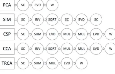
Analysis (CCA)[5], Task-Related Component Analysis (TRCA)[6]. Calculation processes of these algorithms are shown in Figure 1, where SC represents Self-Covariance matrix process, EVD represents EigenValue Decomposition, and W represents Weighting process. It can be found from Figure 1 that these feature extraction algorithms include at least one of EVD or matrix inversion.
Figure 1. Diagram of algorithm flow for common feature extraction methods.
Third, classify EEG signals. After extracting EEG features in step two, EEG signals will be weighted in space or time, and appropriate classification algorithm will be used to classify corresponding tasks. Common classification algorithms include Linear Discriminant Analysis (FLD), linear estimation, Support Vector Machine(SVM), Logistic Regression (LR) [7]. These algorithms mainly consist of simple operations such as addition, multiplication, and division.
The mathematical analysis of EEG signals processing found that the most critical and complex mathematical steps are EVD and matrix inversion. EVD is usually implemented by QRD by following steps. Assume QA=R, then construct . Next, obtain and from using QRD, and then construct . After a finite iteration, get . At this time,
, thereby eigenvalues are obtained.
Matrix inversion can also be achieved by QRD. After QRD, the orthogonal matrix Q and the upper triangular matrix R are obtained from matrix A, and QA=R, so , therefore, . Thus, inversion matrix of A can be calculated by calculating the inverse matrix of the upper triangular matrix R and rightly multiplying the orthogonal matrix Q [8].
Since EVD and matrix inversion can be realized by QRD, we extract QRD as core operator in common EEG algorithms and carry out hardware design.
QRD is mainly implemented by Givens Rotation (GR), Householder Transformation (HT), and Gram-Schmidt Orthogonalization (GSO). GSO is simple and straightforward, but data dependence is strong; HT can eliminate a column of elements to zero at a time, but data dependence of transformation process is large; GR has a high degree of data stability, and only two rows of elements to be rotated are transformed per rotation, so data dependency is small during rotation process. Therefore, GR is chosen as implementation method of QRD in this study.
QR Decomposition Based on Givens Rotation
Using continuous plane rotations, QR decomposition based on Givens Rotation eliminates the elements below the main diagonal of matrix by zero. Each plane rotation is equivalent to matrix A left multiplied matrix . and the identity matrix differ only in both the diagonal elements of i-th row i-th column and the j-th row j-th column and off-diagonal elements of the i-th row j-th column and the j-th row i-th column. For example, for an matrix,
Within one GR, only the i-th and j-th rows of matrix A participate in rotation processes, as shown in the following formula:
It can be found that elements of the i-th column of the j-th row can be eliminated to zero by introducing c and s. left multiply A only modifies elements of the i-th row and the j-th row. Therefore, in order to eliminate the elements below the diagonal of the first column of matrix A to zero, continuous left multiplications , , ..., are required. Similarly, in order to eliminate the elements below the diagonal of the second column of matrix A to zero, a continuous left multiplication of , , ..., are required. By analogy, assuming that A is an n × n matrix, then (n(n-1))/2 times left multiplying matrix are required to convert matrix A into upper triangular matrix R. As shown in the following formula [8]:
High Level Synthesis Design Flow and Implementation
Top level function of QRD algorithm is written by C language, then the IP core that is consistent with C language description is synthesized using High Level Synthesis and Verilog codes are generated. Finally, form a complete FPGA design by synthesis and implementation using Vivado design tools [ 9].
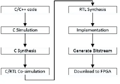
[image:3.595.201.399.566.705.2]As shown in Figure 2, a complete HLS design includes the following steps: 1. C simulation, mainly to verify correctness of the algorithm model, in this step, top level function and test files need to be written. 2. C synthesis, that is, the algorithm is synthesis from the C code into the Verilog code of RTL level. 3. C/RTL co-simulation, used to verify the correctness of the RTL level description. 4. Generate the correct IP core. 5. Perform RTL-level circuit synthesis based on the generated IP core. 6. Add a constraint file and complete FPGA implementation. 7. Generate a bitstream file and download it to the FPGA.
FPGA Implementation Results
In this study, Xilinx VCU118 evaluation board is used as FPGA implementation platform. HLS method is used to generate QRD based IP cores and Vivado design tools are used to synthesis and implementation. Matrix dimensions are based on EEG signals with the 8-lead and 62-lead used by the typical BCI application like SSVEP and RSVP [7]. EEG data will be transformed to 8×8 matrices and 62×62 matrices after SC process.
Two data types are used for FPGA implementation. One is a 32-bit single-precision floating point, and the other is a 16-bit fixed point integer. The format of fixed-point integer is 1 bit for sign bits, 3 bits for integer bits, and 12 bits for decimal bits. System clock is set to 100MHz.
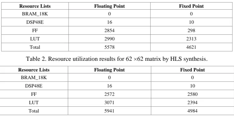
8×8 matrix and 62×62 matrix are synthesized by using two types of data types, floating point and fixed point. Synthesis results by HLS are shown in Table 1 and Table 2.
Table 1. Resource utilization results for 8 ×8 matrix by HLS synthesis.
Resource Lists Floating Point Fixed Point
BRAM_18K 0 0
DSP48E 16 10
FF 2854 298
LUT 2990 2313
[image:4.595.110.486.254.441.2]Total 5578 4621
Table 2. Resource utilization results for 62 ×62 matrix by HLS synthesis.
Resource Lists Floating Point Fixed Point
BRAM_18K 0 0
DSP48E 16 10
FF 2572 2580
LUT 3071 2394
Total 5941 4984
It can be found that for 8×8 matrix, resource consumption by fixed point implementation reduces by 17.16% and calculation speed doubles compared to floating point implementation. However, compared to near 100% calculation precision by floating point implementation, calculation precision by fixed point implementation is reduced by 3.77%. For 62×62 matrix, fixed point implementation is about 3 times faster than floating point implementation, and resource consumption is reduced by 16.11%. It shows that as matrix dimension increases, compared to floating point implementation, calculation clock cycle of QRD by fixed point implementation decreases more, thus improving calculated performance.
Table 3 and Table 4 show that, after FPGA synthesis and implementation, resource utilization results of QRD based on IP core for 8×8 matrix and 62×62 matrix.
Table 3. Resource utilization results after implementation for 8×8 matrix.
Resource Lists Floating Point Fixed Point
LUT 2321 1300
LUTRAM 40 12
FF 1786 878
DSP 16 10
BUFG 1 1
Total 4164 2201
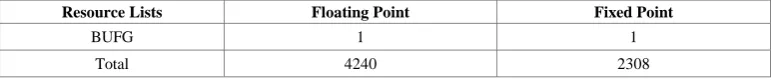
Table 4. Resource utilization results after implementation for 62×62 matrix.
Resource Lists Floating Point Fixed Point
LUT 2421 1411
LUTRAM 40 12
FF 1762 954
Resource Lists Floating Point Fixed Point
BUFG 1 1
Total 4240 2308
It can be found that for 8×8 matrix, after implementation in Vivado, resource utilization by fixed point implementation reduces by 41.74% compared to floating point implementation. For 62×62 matrix, resource utilization by fixed point implementation is reduced by 43.68% compared to floating point implementation.
Table 5 and table 6 show power consumption comparison of floating point and fixed point implementation for 8×8 matrix and 62×62 matrix.
Table 5. Comparison of power consumption for 8×8 matrix.
Power Floating Point Fixed Point
Dynamic/W 0.316 0.184
Static/W 2.474 2.472
[image:5.595.105.491.71.111.2]Total/W 2.79 2.656
Table 6. Comparison of power consumption for 62×62 matrix.
Power Floating Point Fixed Point
Dynamic/W 0.368 0.222
Static/W 2.475 2.473
Total/W 2.843 2.695
It can be seen that static power consumption by fixed point implementation are basically the same as floating point implementation, while dynamic power consumption is reduced by 41.77% and 42.49% for 8×8 matrix and 62×62 matrix, respectively. These results prove that reduction ratio in resource consumption is nearly the same as it in power consumption.
By changing constraints of clock cycle, VCU118 evaluation board can achieve a clock cycle design of up to 3 ns, that is, the operating frequency can reach at least 300 MHz.
Matrix Inversion Based on QR Decomposition
According to Section 2, based on QRD, calculation of inversion matrix only needs to calculate the upper triangular matrix right multiplying the orthogonal matrix Q of. Inversion matrix W of the upper triangular matrix R can be calculated by the following iterative algorithm, so data dependency can be reduced, thereby improving parallelism and calculation speed of hardware design [8]:
[image:5.595.114.483.222.371.2]In this part, a complete matrix inversion IP core is synthesis based implementation results of QRD based IP core in section 5 using High Level Synthesis.
Table 7 and table 8 show HLS synthesis results by floating point and fixed point implementation for 8×8 matrix and 62×62 matrix
Table 7. Resource utilization results of matrix inversion IP core for 8×8 matrix.
Resource Lists Floating Point Fixed Point
BRAM_18K 3 2
DSP48E 16 20
FF 3811 3079
LUT 3985 4093
[image:5.595.124.474.699.779.2]Table 8. Resource utilization results of matrix inversion IP core for 62×62 matrix.
Resource Lists Floating Point Fixed Point
BRAM_18K 16 8
DSP48E 16 20
FF 4526 3201
LUT 4267 4191
Total 8825 7420
It can be found that resource utilization by fixed point implementation reduces by 7.95% for 8×8 matrix and 15.92% for 62×62 matrix, compared to floating point implementation, but data precision is reduced by 4.85% on average.
[image:6.595.101.496.237.488.2]IP core of matrix inversion then performs RTL circuit synthesis and implementation in Vivado design tools. Implementation results of are shown in Table 9 and table 10.
Table 9. Resource utilization results for 8×8 matrix after implementation.
Resource Lists Floating Point Fixed Point
LUT 2786 2208
LUTRAM 49 19
FF 2166 1290
BRAM 1.5 1
DSP 16 8
BUFG 1 1
Total 5019.5 3527
Table 10. Resource utilization results for 62×62 matrix after implementation.
Resource Lists Floating Point Fixed Point
LUT 2934 2367
LUTRAM 46 19
FF 2380 1356
BRAM 8 4
DSP 16 8
BUFG 1 1
Total 5385 3755
Resource consumption by fixed point implementation achieved a reduction by 29.73% for 8×8 matrix and 30.27% for 62×62 matrix, compared to floating point implementation. As dimension of matrix increases, a larger cumulative error occurs, so calculation precision decreases.
For FPGA implementations of floating point data type, resource consumption for 62×62 matrix increases by 7.3% compared to 8×8 matrix. For fixed point implementation, resource consumption for 62×62 matrix increases by 6.46% compared to 8×8 matrix. This indicates that for matrix inversion IP core , resource consumption increases by smaller ratio than matrix dimension, so it is suitable for hardware design of large dimension matrix inversion.
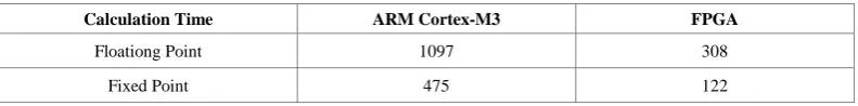
[image:6.595.101.497.654.703.2]Finally, calculation time by IP core of matrix inversion is compared ARM Cortex-M3 platform, as shown in Table 11.
Table 11. Comparison of calculation time of 62×62 matrix inversion on different platforms.
Calculation Time ARM Cortex-M3 FPGA
Floationg Point 1097 308
Fixed Point 475 122
Conclusions and Prospects
matrix, it is found that fixed point implementation reduces at least 40% of hardware resource consumption and improved at least 100% of calculation speed. Finally based on this QRD based IP core, matrix inversion IP core is implementation, and its calculation speed is three times faster than ARM Cortex-M3 platform.
Since FPGA implementation of QRD using High Level Synthesis, it is easily scalable for implementation of arbitrary dimension matrices. Meantime, for different requirements of size, power consumption and speed in BCI, we can choose appropriate data types to implement QRD based IP core.
Acknowledgement
Research was supported by the National Key Technologies R&D Program(2017YFA0701100, 2017YFA0205903); National Natural Science Foundation of China (61634006); e Key Research Program of Frontier Science, Chinese Academy of Sciences (Grant No. QYZDY-SSW-JSC004).
References
[1]Schalk G, Mcfarland D J, Hinterberger T, et al. BCI2000: a general-purpose brain-computer interface (BCI) system[J]. IEEE transactions on bio-medical engineering, 2004, 51(6):1034.
[2]Tipping M E, Bishop C M. Probabilistic Principal Component Analysis[J]. Journal of the Royal Statistical Society: Series B (Statistical Methodology), 1999, 61.
[3]Wu Wei. Research on spatio-temporal modeling of multi-lead EEG signals based on statistical modeling [D]. Tsinghua University, 2012.
[4]Fukunaga K , Koontz W L G . Application of the Karhunen-Loève Expansion to Feature Selection and Ordering[J]. IEEE Transactions on Computers Archive, 1970, 19(4):311-318.
[5]Hotelling, H. Relations Between Two Sets of VariaTES[J]. Biometrika, 1936, 28(3-4):321-377.
[6]Li J, Wang Y, Zhang L, et al. Decoding EEG in Cognitive Tasks With Time-Frequency and Connectivity Masks[J]. IEEE Transactions on Cognitive & Developmental Systems, 2017, 8(4):298-308.
[7]Gerson A D, Parra L C, Sajda P. Cortically coupled computer vision for rapid image search[J]. IEEE Transactions on Neural Systems and Rehabilitation Engineering, 2006, 14(2):174-179.
[8]El-Amawy A, Dharmarajan K R. Parallel VLSI algorithm for stable inversion of dense matrices[J]. IEE Proceedings E - Computers and Digital Techniques, 2005, 136(6):575-580.