2019 International Conference on Computation and Information Sciences (ICCIS 2019) ISBN: 978-1-60595-644-2
Minimum Displacement Calculation Method of
Killing Well Control Technology by
Bullheading
Qingfeng Li, Hu Yin, Menghan Si and Qian Li
ABSTRACT
After gas invasion and shut-in, the displacement which can completely remove the gas in the wellbore is called the minimum displacement. This paper studies how to calculate the minimum displacement. By analyzing the characteristics of fluid flow in closed wellbore after shut-in, the conditions for complete removal of gas are obtained, and the minimum displacement calculation method is obtained according to the removal conditions. The upward slippage of bubbles and the downward flow of liquid phase around the gas are the reasons why the gas cannot be completely removed under too small displacement; According to the characteristics of Bullheading, bubbles will slip upward in the form of small bubbles in the process of Bullheading; Based on the phenomenon of water seal, a formula for calculating the minimum velocity to avoid the flow around liquid phase is deduced; By comparing the minimum downward velocity of killing fluid and bubble slippage velocity, the minimum displacement is obtained by taking the larger values of the two as the calculation basis.
1. INTRODUCTION
If there is a pure gas column in the wellbore after gas invasion and shut-in, it is necessary to completely remove the gas from the wellbore to the formation by using liquid, such as Bullheading. The liquid displacement is the key factor to
determine whether the gas can be completely removed. In this paper, the minimum displacement is defined as the displacement that can completely remove the gas in the wellbore. How to calculate the minimum displacement is studied and analyzed in this paper.
At present, many scholars have studied this problem: Koedoritz[1] uses water and low viscosity drilling mud as killing fluid, and gas as formation fluid. Full-scale experiments have been carried out to evaluate the main factors affecting the removal efficiency of Bullheading method. It is found that the gas cannot be completely removed under the condition of small displacement. The formula of minimum displacement of killing fluid is deduced by mathematical method based on the experimental results. In 2013, Ren Meipeng[2] and others considered that the flow rate of killing fluid was affected by flooding phenomenon, that is, in the process of gas-liquid two-phase counter-flow, the liquid was partially or totally brought out of the flow passage by dragging force of gas. In 2016, Liu Shujie[3] and others considered that the minimum displacement of killing should be greater than the slippage velocity of gas, and calculated by Harrnathy[4] single bubble slippage rise formula in infinite watershed. In 2018, Sun Baojiang and others believed that the Taylor bubble was the fastest rising velocity of the invaded annular air body in the killing fluid. As long as the Taylor bubble could be pressed back into the formation, the rest of the gas could also be pressed back into the formation. Therefore, the maximum slip rate of the invaded annulus in killing fluid is calculated by the slug flow rising rate formula.
Taking shut-in as the precondition, this paper analyses the condition of completely removing gas from liquid in sealed wellbore. Based on the theory of "water seal phenomenon" and gas continuity, the minimum displacement around liquid phase is analyzed theoretically, and the minimum downward velocity of killing fluid is deduced. Combined with the characteristics of bubble slippage in closed wellbore, the calculation method of minimum displacement of killing fluid is given.
2. ANALYSIS OF FACTORS AFFECTING MINIMUM DISPLACEMENT
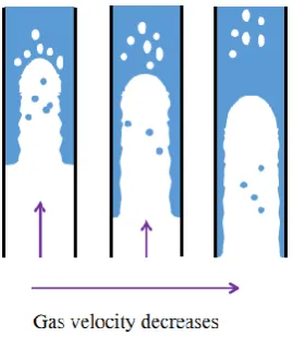
formation gas invasion rate gradually decreases, and the gas flow rate gradually decreases. As the gas flow rate in the wellbore decreases gradually, the relative velocity of gas-liquid interface decreases, and the shear force decreases, the downward fluid eventually flows smoothly along the channel wall from top to bottom into a uniform liquid film. During the whole killing process, due to the difference of gas-liquid density, the bubble will slip upward in the liquid phase [5].
Figure 1. Gas-liquid countercurrent diagram.
That is to say, it is impossible to completely remove the gas in the wellbore because the liquid flow will flow downward around the gas when the discharge is too small, and the gas will slip upward in the form of bubbles in the killing process. To ensure the complete removal of gas in wellbore, downward velocity of killing fluid must satisfy two conditions:
·The slippage velocity is greater than that of the bubble. The gas-liquid two-phase section moves downward as a whole, preventing gas from sliding upward, polluting drilling fluid and reducing hydrostatic column pressure, and bringing bottom hole high pressure to the wellhead.
·Bottom-hole fluids cannot bypass gas. The bottom hole gas column is pushed back to the formation completely, so that the bottom hole gas slips and rises again and secondary overflow accident occurs when the cycle is rebuilt.
3. MINIMUM DISPLACEMENT CALCULATION
3.1 Analysis of Bubble Slipping Characteristics in Closed Wellbore
goes down and gas flows backwards. According to Gongpeibin high pressure annulus multiphase flow gas slippage velocity experiment conclusion [6]: high wellhead back pressure can inhibit the instability of bubbly flow, under the same conditions, the higher wellhead pressure, the higher the section gas holdup required for bubbly flow stability; the section gas holdup required for bubbly flow stability increases with the increase of liquid flow velocity. Therefore, it can be considered that the gas will slip upward and rise in the form of small bubbles. Hadamard[7] considered the influence of gas circulation in the bubble caused by viscous shear force on the slippage velocity of the bubble in the process of rising small bubbles, and proposed the following calculation formula:
l g
l
b
gd
v 2 /12
(1)
3.2 How to avoid liquid phase bypassing gas flow analysis
With regard to how to avoid the downward flow of downward liquid around gas, this paper analyses the phenomenon of "water seal" in Li Xichuan's gas-liquid counter-flow experiment[8], and obtains the conditions for avoiding the downward flow of liquid by combining the gas-to-gas continuity mechanism in wellbore.
·In unit time, the volume holdup of downward liquid is more than 0.25. If the gas phase is discontinuous, the downstream fluid can not be atomized, so that the effective hydrostatic column pressure can be maintained.
·When the bottom hole pressure balances the formation pressure, the increment of hydrostatic column pressure is greater than that of gas column pressure. To ensure that the liquid phase can enter the gas phase, the gas column is compressed down, and the liquid phase can not be ejected.
In order to simplify the analysis, this paper considers that if the hydrostatic column pressure generated by downward liquid in unit time can seal the gas column pressure generated by compressed gas in unit time, the increased hydrostatic column pressure will surely seal the increased gas column pressure when the bottom hole pressure balances the formation pressure.
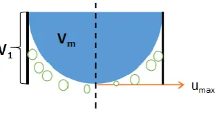
Figure 2. Velocity distribution of liquid in annulus per unit time.
As shown in Fig. 2, the downward velocity of killing fluid is Umax at the axis. The volume of killing fluid entering the gas column is Vm, and the volume of the whole annular space is V1. If the gas phase cannot be continuous, then:
25 . 0 1 V Vm (2)
If the gas gravity is neglected, the initial wellhead pressure can be approximately considered as the initial gas column pressure increment PC0.The increment of gas column pressure per unit time is:
0 1 c c
c P P
P
(3) 1 1 1 0 m c c V V V P P (4)
The hydrostatic column pressure produced by killing fluid in unit time:
max gu Ph k
(5)
c
h P
P
(6)
According to formula (3):
g V V V P u m c 1 0 max (7) g P u k c 0 max 33 . 0 (8)
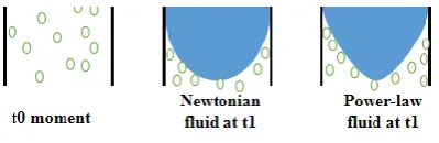
fluids and different flow patterns. This paper only analyses Newtonian fluid and power law fluid(Fig. 3).
Figure 3. Distribution of downward velocities of different types of fluids in unit time.
Newtonian fluid
Average laminar velocity of Newtonian fluid u: Power law fluid
max 2 1 u u
(9)
For killing fluids and drilling fluids, they are generally laminar flow with small displacement.
Average laminar velocity of power-law fluid u:
max
1 3
1
u n n u
(No drilling tools) (10)
max
1 2
1
u n n u
(Annulus) (11)
3.3 Minimum displacement calculation method
By comparing the slippage velocity of bubbles with the minimum velocity of avoiding liquid flow, the calculation basis of the minimum displacement is the larger of the two.
A u v
Qmin max( , ) (12)
4. CONCLUSIONS
2. According to the characteristics of Bullheading killing in closed wellbore, wellhead high pressure pushes wellbore fluid back to formation, downward flow of killing fluid and reverse flow of gas, it is concluded that bubble will slip upward in the form of small bubbles in the process of Bullheading killing. According to the phenomenon of water seal and the mechanism of gas continuity, the formula for calculating the minimum velocity of avoiding liquid flow is deduced.
3. By comparing the slippage velocity of bubbles and the minimum velocity needed to avoid bypassing flow, the calculation method of the minimum displacement of killing well is obtained by taking a larger value as the basis of calculation.
Symbol Comment
v
,Slippage velocity, m/s ;g, Gravity acceleration, 2/s
m ; l ,Liquid
density, 3 /m
kg ;g ,Gas phase density,
3 /m
kg ;l ,Liquid phase viscosity,
s
mPa ; db ,Bubble Equivalent Diameter,m ;Vm,Volume of liquid phase
entering gas phase per unit time, 3
m ;V1,Gas volume per unit time, 3
m ;Pc1,Air
column pressure per unit time,MPa;Pc0,Initial gas column pressure,MPa;
c
P
,Gas column pressure increment per unit time,MPa ;Ph ,Hydrostatic
column pressure,MPa;umax,Maximum downward velocity of liquid phase,
s
m/ ;u,Average downward velocity of liquid phase,m/ ;s nIndices that vary
with Reynolds number;Qmin, Minimum well killing displacement,m3/s;A,
Cross-sectional area, 2
m .
REFERENCES
1. Koederitz W L. 1995. "Gas kick behavior during bullheading operations in vertical wells,"
Louisiana State University and Agricultural & Mechanical College, 1995.
3. Liu, S., Ren, M., Li, X., and Wang, Y. 2016. "Parmeter-changing pattern and design method of bullheading killing method of Study on two-phase gas-liquid flow during gas kick," China offshore oil and gas, 28(05), 71-77
4. Harmathy, T. Z. 1960. "Velocity of large drops and bubbles in media of infinite or restricted
extent," AIChE Journal, 6(2), 281-288
5. XinzhongG. 2018. "Mechanism and critical parameters of liquid-carrying behaviors in gas wells," Natural Gas Industry, 2018.
6. PeiBing, G., Baojiang, S., and Zhiyuan, W. 2012. "Study on killing method for in-well
blow-out condition," Journal of Oil and Gas Technology(34.1)
7. Leal L G. 1979. "Bubbles, drops and particles : R. Clift, J.R. Grace and M.E. Weber.
Academic Press, 1978.380pp," International Journal of Multiphase Flow, 1979, 5(3):229-230.
8. Xichuan Li, Zhongning S. 2012. "Study of flooding in vertical narrow rectangular channels,"