Buckling Analysis of Composite Cylindrical Shell under
Cryogenic Environments
Widad I. Al-Azzawi
Mechanical Engineering Dep. Baghdad Univ. Zayona-Baghdad, Iraq
Ibtehal A. Sadiq
Mechanical Engineering Dep. Baghdad Univ. Khadimya-Baghdad, Iraq
ABSTRACT
Buckling analysis of laminated composite simply supported cylindrical shell under cryogenic environment is solved by using exact approach. The theoretical formulation is based upon the third-order shear deformation theory, then equation of motion are derived and solved using Fourier series to obtain critical buckling load by solving eigenvalue problem for different cryogenic gradients. Many design parameters are changed such as using different material, number of laminate, aspect ratio (L/R) and thickness ratio (R/h). Results show that changing cryogenic temperature improve buckling load for all material of cylindrical shell, the results show good agreement with those published by other researchers.
General Terms
Modeling,stabilityKeywords
Buckling, Composite material, Cryogenic, Shell, Cylindrical, Shell theory.
1.
INTRODUCTION
Composite materials used widely for many engineering applications such as aerospace, pressure vessels for storing liquid hydrogen and liquid oxygen for spacecraft propellant because of their high strength to weight and stiffness to weight ratios. Tudela, M., and Kim, R. [1] found that the total pressure vessel weight could be reduced by as much as 35 percent when they replaced all metallic vessel by composite materials.
Shells (conical frusta, cylindrical panels and shallow trusses) subjected to external pressure is prone to buckling rather than strength failure. The main feature of such shell structures is to absorb the energy generated due to impact heavy loads and can fail due to buckling. William L. Ko [2], used the finite element method to analyze thermocryogenic buckling and stress on a horizontally oriented cryogenic tank. The tank is a finite-length circular cylindrical shell with its two ends capped with hemispherical shells which subjected to cylindrical strip heating in the region above the liquid-cryogen fill level and to cryogenic cooling below the fill level. The buckling temperature was sensitive to the radius-to-thickness ratio and insensitive to the cryogen fill level but stress magnitudes were relatively insensitive to the cryogen fill level. A. Nikroo et al [3], presented an overview of buckle and burst pressures of several different types of glow discharge polymer (GDP) shells using traditional GDP deposition parameters under high deposition pressure and using modified parameters “strong GDP” of low deposition pressure that leads to more robust shells.
Hui-Shen Shen
[4], used classical shell theory with von Kármán–Donnell-type of kinematic nonlinearity to derive the governing equations of postbuckling analysis for a functionally graded cylindrical thin shell of finite length subjected to compressive axial loads and in thermalenvironments. Material properties graded in the thickness direction according to a simple power law distribution. Some parameters are studied such as temperature rise, volume fraction distribution, shell geometric parameter, and initial geometric imperfections. L. Scatteia et al [5], studied the applicability of polymer based composites to lightweight reusable liquid propellant tanks so as to design, manufacture and test a scaled demonstrator composite tank within the Italian Unmanned Space Vehicle (USV)-CRYOTANK project.
Lanhe Wu
et al [6], derived the equilibrium and stability equations of the functionally graded cylindrical shell subjected to thermal loads Based on the Donnell‟s shell theory. The effects of the aspect ratio, the relative thickness and the functionally graded index on the buckling temperature difference are carefully discussed. Himayat Ullah and Sagheer Ahmad [7], investigated buckling of thin walled cylindrical shells under axial compression using analytical, numerical and semi empirical models. Classical Shell small deflection theory is the base of analytical model while a semi empirical model is obtained by employing experimental correction factors based on the available test data to the theoretical model and using ANSYS FEA Code numerically. The comparison reveals that analytical and numerical linear model results match closely with each other but are higher than the empirical values.M. Shariyat
[8], presented dynamic buckling of a pre-stressed, suddenly heated and mechanically loaded imperfect FGM cylindrical shell in thermal environment. The equations of motion are derived using high order shell theory. Two different materials are used to study the influence of temperature-dependency of the material properties, volume fraction index, load combination, and initial geometric imperfections on the thermo-mechanical post-buckling behavior of a shell. The results shows that the volume fraction index may change the buckling behavior also temperature gradient and initial imperfections have less effect on buckling of a shell subjected to a pure external pressure. B. Prabu et al [9], used ANSYS FE non-linear buckling analysis of cylindrical shell including both material and geometrical non-linearities to determine the critical buckling pressure for three types of geometrical imperfection patterns. From the analysis it is found that when the maximum amplitude of imperfections is 1t, the eigen affine imperfection pattern gives out the lowest critical buckling pressure when compared to the other imperfection patterns considered.Figure 1: Cylinder geometry (L axis≡ axis 1, θ axis ≡ axis 2 & R axis ≡ axis 3).
)
,
,
(
)
,
,
(
)
,
,
(
)
,
,
(
)
,
,
,
(
x
z
t
u
0x
t
z
1x
t
z
2 1x
t
z
3 1x
t
u
) , , ( ) , , ( ) , , ( ) , , ( ) , , ,
(x zt v0x t z 2 x t z2 2 x t z3 2 x t v
)
,
,
(
)
,
,
,
(
x
z
t
w
0x
t
w
(1) The resulting strain-displacement relations are: 2 0 2 1 2 3 1 0 1 3 4 x w x H z x z x
u
2 0 2 0 2 2 3 2 0 0 2 1 1 3 4 1 w R v R H z z w v R 0 3
x w R x v R R x H z x R z u R x v 0 2 0 1 2 2 3 2 1 0 0 6 2 1 1 3 4 1 1
0 02 2 2 0 0 2 4 1 4 1 w R R v H z w R R v
x
w
H
z
x
w
0 1 2 2 0 1 54
(2)According to Hamilton‟s׳ Principles:
01 2
t t t W U (3)
Where:
A z dzdx Rd U
4 4 5 5 6 6 3 3 2 2 1 1
A zx
R
dzdxd
x
w
N
W
2)
(
2
1
Following third order theory, the critical value of (in-plane) compressive load (Nx) subjected to a simply supportedlaminated closed cylindrical shell is obtained, the equations of motion are: 0 1 6 1
N R xN (4)
0 1
3 4
4 2 6
2 4 2 4 6 2 x S S R H K H Q x N R N (5) 0 4 2 1 3 4 2 2 5 4 5 4 2 2 6 2 2 1 2 2 2 2 2 x w N x Q R Q x K R K H N x S x S R S R H x (6) 0 4 3 4 3 4 5 2 5 6 2 6 1 2 1 K H R RQ S H R M x S H R x M R (7) 4 0 3 4 3 4 4 2 4 6 2 6 2 2 2 K H R RQ x S H R x M R S H R M
(8)
Where:
,
1, 4,56 , 2 , 1 , , 1 , , 2 3
i dz z Ki Qi i dz z z Si Mi Ni i i Substituting the resultants forces in motion-equations and then the assumed displacement components according to Navier׳s Solution [11] (for simply supported boundary conditions), the stiffness matrix is obtained.
i mnm n mn mn i m n mn
e
x
B
t
z
x
v
e
x
A
t
z
x
u
1 1 0 1 1 0cos
sin
,
,
,
sin
cos
,
,
,
i mnm n mn mn i m n mn e x D t z x e x C t z x w
1 1 1 1 1 0 sin cos , , , sin sin , , ,
i mnm n
mn x e
E t
z
x
1 12 , , , sin cos (9)
Where n L m
,and rearranging the obtained matrix we get:
0 2 1 11 12 15 14 13 21 22 25 24 23 51 52 55 54 53 41 42 45 44 43 31 32 35 34 2 33 U V W C C C C C C C C C C C C C C C C C C C C C C C C N C x (10)
Following the condensation of variables procedure to eliminate the displacement components (U,V,ϕ1,ϕ2 ). Using experimental solution that fits the changing of modulus of elasticity with temperature from (11) to (14), results in changing of stiffness matrix [C] and then changing eignvalues that obtained by solving (10). The following expressions obtained by linear fitting for composite material which show that (E1, E2, G12 in MPa and υ12 are function of temperature
of small period of time and there is no possibility of changing the modulus of elasticity of these period) [12].
Carbon-Epoxy
3562
.
75
0784325
.
0
1
T
E
24092
.
8
00878597
.
0
2
T
E
57018
.
4
00618578
.
0
12
T
G
221194 . 0 000244411 .
0
12 T
(11)
Carbon-Polyester
3642
.
51
0494144
.
0
1
T
E
32907
.
7
00857159
.
0
2
T
E
18697
.
2
00527408
.
0
12
T
G
310163 . 0 000267386 .
0
12 T
(12)Glass-Epoxy
7255
.
28
0381124
.
0
1
T
E
90224
.
6
0113027
.
0
2
T
E
44244
.
3
00828687
.
0
12
T
G
261837
.
0
000157951
.
0
12
T
(13)Glass-Polyester
7981
.
20
029007
.
0
1
T
E
12469
.
6
0107885
.
0
2
T
E
41934
.
2
00475636
.
0
12
T
G
33342
.
0
000316521
.
0
12
T
(14)3.
RESULTS AND DISCUSSION
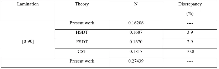
Buckling of composite laminated cylindrical shells under axial compression with different design parameters under simply supported boundary condition, are analyzed and solved using Fortran programming. the critical value of (Nx ) N/m is
obtained and compared with that published in [13] as shown in Table (1).
The critical buckling load for shells made from four different materials are obtained as shown in Table (2) for different number of unsymmetric cross-ply lamination under different cryogenic temperatures, which shows the minimum buckling load was for shells with two layers made from glass-polyester under 25C0 temperature (0.81596) and it is increasing with increasing number of layers and decreasing temperature because the stiffness of shell increase with decreasing cryogenic temperature which means cryogenic environments improves mechanical properties.
While critical buckling load for different number of symmetric cross-ply lamination shells made from four different materials are obtained as shown in Table (3) under different cryogenic temperatures, which shows the minimum buckling load was for shells with three layers made from glass-polyester under 25C0 temperature (0.60697) and it is increasing with increasing number of layers and decreasing temperature, however the unsymmetric lamination critical load is (20.18%) greater than that for symmetric one for the four layers.
Table (4) shows the critical buckling load for symmetric and unsymmetric cross-ply laminated plate for the four materials under different aspect ratio (L/R) and thickness ratio (R/H) at temperature 25 Co, which decrease with increasing both of the radius to thickness ratio (R/H) and length to radius ratio (L/R) which gives minimum buckling load (0.01283) for unsymmetric two ply shells made from glass-polyester. The weakest unsymmetric (0-90) cylindrical shells critical buckling is obtained in Table (5) for (epoxy, carbon-polyester, glass-epoxy and glass-polyester) under different thickness ratio and cryogenic temperature with aspect ratio =10, which shows that increasing thickness ratio will decrease buckling load of the shell while decreasing temperature will again improve it for all materials.
4.
CONCLUSIONS AND FUTURE
SCOPE
4.1 Conclusions
Analytical solution for buckling of general third-order shell theories are applied to cross-ply cylindrical shells. For the same ((R/H), (L/R)) cylindrical shells buckling load changes directly with the number of layers but changes indirectly with cryogenic temperatures because some mechanical properties are proved under these environment which results in increasing buckling load of unsymmetric two layer cylindrical shell made from glass polyester (35.9 %), also unsymmetric lamination undergo greater buckling load than that taken by symmetric scheme, but these loads changed indirectly with (R/H) and (L/R), however length to radius ratio is more significant on changing buckling load, also as known the weakest composite material is glass-polyester.
4.2 Future Scope
[image:3.595.50.240.112.411.2]We suggest to investigate post buckling of shell with different shape, changing the shape of axial load and changing boundary condition of the shell under cryogenic environment.
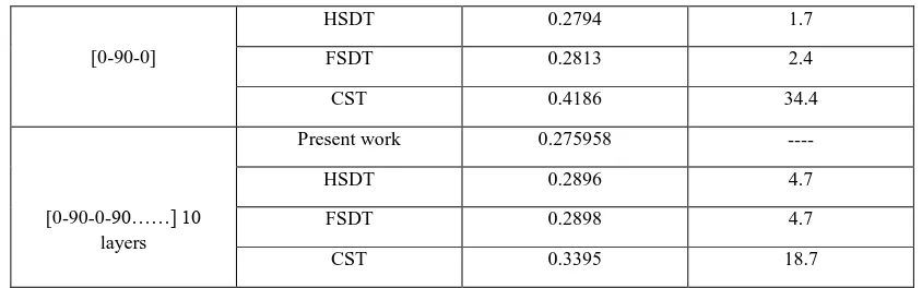
Table 1: The dimensionless critical buckling loads of cross-ply circular cylindrical shell as predicted by various theories.( L/R=1, R/H=10, N=NL^2/100H^3E2), [13]
Lamination Theory N Discrepancy
(%)
[0-90]
Present work 0.16206 ----
HSDT 0.1687 3.9
FSDT 0.1670 2.9
CST 0.1817 10.8
[image:3.595.89.508.630.763.2][0-90-0]
HSDT 0.2794 1.7
FSDT 0.2813 2.4
CST 0.4186 34.4
[0-90-0-90……] 10 layers
Present work 0.275958 ----
HSDT 0.2896 4.7
FSDT 0.2898 4.7
[image:4.595.86.508.72.204.2]CST 0.3395 18.7
Table 2: Critical buckling (Ncr) for un-symmetric cross-ply laminated shell (carbon-epoxy, carbon-polyester, glass-epoxy and glass-polyester) under different temperature environments (H=1, R=10, L=100).
Un-symmetric 2 – Layer (0- 90)
Temp. (C0)
Carbon-Epoxy Carbon-polyester Glass-Epoxy Glass-polyester
25 1.7189 1.1542 1.0030 0.81596
-50 1.8587 1.3184 1.1250 0.92245
-100 1.9518 1.4251 1.2062 0.99395
-150 2.0449 1.5301 1.2875 1.0659
-180 2.1006 1.5924 1.3363 1.1093
Un-symmetric 4 – Layer (0-90-0-90)
Temp. (C0) Carbon-Epoxy Carbon-polyester Glass-Epoxy Glass-polyester
25 2.0701 1.1775 1.1118 0.82953
-50 2.2622 1.3449 1.2647 0.93985
-100 2.3902 1.4536 1.3655 1.0136
-150 2.5182 1.5606 1.4658 1.0876
-180 2.5950 1.6242 1.5257 1.1321
Un-symmetric 6 – Layer (0-90-0-90-0-90)
Temp. (C0) Carbon-Epoxy Carbon-polyester Glass-Epoxy Glass-polyester
25 2.0844 1.1851 1.1176 0.83338
-50 2.2778 1.3535 1.2712 0.94416
-100 2.4067 1.4629 1.3725 1.0182
-150 2.5355 1.5706 1.4732 1.0925
-180 2.6129 1.6346 1.5334 1.1372
Table3: Critical buckling (Ncr) for symmetric cross-ply laminated shell (carbon-epoxy, carbon-polyester, epoxy and glass-polyester) under different temperature environments (H=1, R=10, L=100)
Symmetric 3 – Layer (0-90-0)
Temp. (C0) Carbon-Epoxy Carbon-polyester Glass-Epoxy Glass-polyester
25 1.0921 0.84484 0.71691 0.60697
-50 1.1849 0.92693 0.80943 0.69187
-100 1.2469 0.98149 0.87125 0.74915
-180 1.3464 1.0687 0.97045 0.84207
Symmetric 4 – Layer (0-90-90-0)
Temp. (C0) Carbon-Epoxy Carbon-polyester Glass-Epoxy Glass-polyester
25 1.4721 1.0960 0.83910 0.69023
-50 1.5954 1.1964 0.94340 0.78371
-100 1.6778 1.2633 1.0131 0.84682
-150 1.7603 1.3302 1.0829 0.91062
-180 1.8099 1.3703 1.1250 0.94926
symmetric 6 – Layer (0-90-0-0-90-0)
Temp. (C0) Carbon-Epoxy Carbon-polyester Glass-Epoxy Glass-polyester
25 2.1506 1.3093 1.0665 0.84455
-50 2.3297 1.5029 1.1936 0.95404
-100 2.4493 1.6288 1.2785 1.0279
-150 2.5691 1.7528 1.3636 1.1027
-180 2.6411 1.8265 1.4147 1.1480
Table4: Critical buckling (Ncr) for symmetric and un-symmetric cross-ply laminated shell (carbon-epoxy, carbon-polyester, glass-epoxy and glass-polyester) under different aspect ratio at temperature (T = 25Co ).
Un-symmetric 2 – Layer (0- 90)
Carbon-Epoxy Carbon-polyester Glass-Epoxy Glass-polyester
R/H L/R = 10 L/R= 100 L/R = 10 L/R = 100 L/R = 10 L/R = 100 L/R = 10 L/R = 100 10 1.7189 0.0420 1.1542 0.0287 1.0030 0.019189 0.81596 0.01444 20 0.5838 0.040 0.4229 0.027998 0.3181 0.017413 0.2529 0.013167 50 0.2607 0.0397 0.1736 0.027942 0.1262 0.016997 0.096133 0.012862 100 0.1543 0.0398 0.1146 0.027993 0.0838 0.016966 0.067104 0.01283
symmetric 3 – Layer (0- 90-0)
Carbon-Epoxy Carbon-polyester Glass-Epoxy Glass-polyester
R/H L/R = 10 L/R = 100 L/R = 10 L/R = 100 L/R = 10 L/R = 100 L/R = 10 L/R = 100
10 1.0921 0.0542 0.8448 0.03673 0.7169 0.02316 0.6069 0.01711
20 0.4609 0.0514 0.3305 0.03542 0.2641 0.02112 0.2149 0.01566 50 0.2821 0.0506 0.1837 0.03505 0.1359 0.02055 0.1037 0.01526 100 0.1140 0.0505 0.0854 0.03500 0.6549 0.02047 0.05405 0.015203
Table5: Critical buckling (Ncr) for un-symmetric (0-90) cross-ply laminated shell (carbon-epoxy, carbon-polyester, glass-epoxy and glass-polyester) under different thickness ratio under cryogenic temperature (R=10, L=100)
Carbon-Epoxy
Temp. (C0) R/H =10 R/H =20 R/H =50 R/H =100
25 1.7189 0.5838 0.2607 0.1543
0 1.7655 0.59948 0.26791 0.15847
-100 1.9518 0.66191 0.29629 0.17476
-180 2.1006 0.7115 0.3118 0.1877
Carbon-Polyester
Temp. (C0) R/H =10 R/H =20 R/H =50 R/H =100
25 1.1542 0.4229 0.1736 0.1146
0 1.2096 0.43535 0.17923 0.11786
-50 1.3184 0.46001 0.19020 0.12416
-100 1.4251 0.48444 0.20095 0.13044
-180 1.5924 0.5231 0,2178 0.1404
Glass-Epoxy
Temp. (C0) R/H =10 R/H =20 R/H =50 R/H =100
25 1.003 0.3181 0.1262 0.0838
0 1.0437 0.33070 0.13113 0.087077
-50 1.1250 0.35582 0.14089 0.093576
-100 1.2062 0.38087 0.15058 0.10006
-180 1.3363 0.4208 0.1660 0.1104
Glass-Polyester
Temp. (C0) R/H =10 R/H =20 R/H =50 R/H =100
25 0.8159 0.2529 0.0961 0.0671
0 0.85137 0.26348 0.099968 0.069899
-50 0.92245 0.28463 0.10761 0.075498
-100 0.99395 0.30582 0.11524 0.081112
-180 1.1093 0.3398 0.1274 0.0901
Nomenclature
Amn, Bmn, Cmn, Dmn, Emn Arbitray constants
Cij stiffness matrix elements
E1, E2 Elastic Modulus components (Gpa)
G12 Shear modulus component (Gpa)
H Thickness (mm)
L Cylinder length (mm)
m, n indicies
Ni ,Mi, Si, Qj, Kj (i=1,2,3,6),
(j=4,5)
Resultant reactions (N/mm),(N.mm)
Nx Buckling load (N/mm)
R Cylinder radius (mm)
T Temperature (C0)
U Potential energy (J)
W Work (J)
u0, v0, w0 ,φ1, φ2 Displacement components at neutral axis (mm)
Z Distance from neutral axis (mm)
ε 1,2,3,4,5,6 Strain components
υ12 Poisons ratio components
σ1,2,3,4,5,6 Stress components (Mpa)
5.
REFERENCES
[1] Tudela, M., and Kim, R. “Impact Damage Response of Composite Materials at LOX/Cryogenic Temperatures,” AIAA, 2157, pp.4356-4367, 2005.
[2] William L. Ko "Thermocryogenic Buckling and Stress Analysis of a Partially Filled Cryogenic Tank Subjected to Cylindrical Strip Heating" National Aeronautics and Space Administration Office of Management Scientific and Technical Information Program, 1994.
[3] A. Nikroo, D.G. Czechowicz, K.C. Chen, M. Dicken,i C. Morris,$ R. Andrews, A. Greenwood, and E. Castillo "Mechanical Properties of Thin GDP Shells Used As Cryogenic Direct Drive Targets At Omega" University of California, September 2003.
[4] Hui-Shen Shen Postbuckling analysis of axially-loaded functionally graded cylindrical shells in thermal environments, Composites Science and Technology, Vol.62, Issues 7–8, June 2002, pp.977–987
[5] L. Scatteia, G. Tomassetti, M. Kivel Mazuy, S. Cantoni,‟Prora USV- Tech cryotank project Applicability of CFRP to tank manufacturing for cryogenic liquid propulsion‟,54th International astronautical congress of
international astronautical federation, the international academy of astronautics, and the international institute of space law,29 September-3 October 2003, Bermen, Germany.
[6] Lanhe Wu, ,Zhiqing Jiang,Jun Liu,‟ Thermoelastic stability of functionally graded cylindrical shells‟
,Composite Structures, Vol.70, Issue 1, August 2005,pp.60–68.
[7] Himayat Ullahand Sagheer Ahmad,‟Buckling Stability of Thin Walled Cylindrical Shells Under Axial Compression‟, Failure of Engineering Materials & Structures Code 48 UET Taxila Mechanical Engineering Department, (2007).
[8] M. Shariyat,‟ Dynamic thermal buckling of suddenly heated temperature-dependent FGM cylindrical shells, under combined axial compression and external pressure‟, International Journal of Solids and Structures, Vol.45, Issue 9, 1 May 2008, Pp.2598–2612
[9] B. Prabu , N. Rathinam, R. Srinivasan, K.A.S. Naarayen,‟ Finite Element Analysis of Buckling of Thin Cylindrical Shell Subjected to Uniform External Pressure‟, Journal of Solid Mechanics Vol.1, No.2 (2009) pp.148-158.
[10]Shruti Deshpande, M. S.,‟Buckling And Post Buckling Of Structural Composites‟, M.Sc. thesis, the University of Texas at Arlington, 2010.
[11]J.N. Reddy, „Mechanics of laminated composite plates and shells‟, CRC Press 2004.
[12]Ebtihal A. Sadiq "Dynamic Response Of Composite Plates Under Cryogenic Environment"Thesis,University of Baghdad, 2009.