Improving the Security of Image Encryption by using
Two Chaotic Maps
N. F.Elabady
Computer Science Department, Faculty of Computers and Informatics,
Benha University, Benha, Egypt
M. I. Moussa
Computer Science Department, Faculty of Computers and
Informatics, Benha University,
Benha, Egypt
S. F. Sabbeh
Information System Department, Faculty of Computers and
Information, Benha University, Benha,
Egypt
H. M.Abdalkader
Information System Department, Faculty of Computers and Information, Menofia University,
Shebien, Egypt
ABSTRACT
During the recent years several chaotic image encryption algorithms based on one dimensional (1-D) have been proposed, but the drawbacks of small key space, low speed, and low security in 1-D chaotic cryptosystems are obvious. This paper proposes a new image encryption technique based on 1-D and 2-D chaotic maps which provide more security and big key space. The 1-D chaotic system is induced from a mathematical combination between the logistic map and the cubic chaotic map. It has the advantage of bigger key space and high security analysis such as key space analysis, statistical analysis and sensitivity analysis were carried out. The proposed system uses 1-D and 2-D chaotic maps for simultaneous encryption of the components R, G, B of the colored image; these three components affect each other. So, the security and confidentiality of image data become more important. The security of digital images and performance speed has become more important since the communications of digital information over network occur more frequently. An image encryption has applications in various fields for example; the internet communication, the multimedia systems, the medical imaging, Tele-medicine and the military communication. The image encryption's aim is to convert the original image to another image that is hard to understand. However, image encryption differs from text encryption due to some intrinsic features of images which include bulk data capacities, high redundancy, strong correlations among pixels, etc. These features make conventional cipher systems such as DES, AES and RSA unsuitable for practical image encryption [1]. The chaos theory is used in cryptography due to its intrinsic features. These properties of chaos includes: sensitivity to initial condition and control parameters, random like behavior and mixing property, etc [2]. Several chaos based image encryption approaches have been described. The first is the confusion approach where the position of pixels scrambled without changing the values of pixels, the application of this approach does not guarantee a good level of security [3]. The second approach is the diffusion which aims to change the value of each pixel in the whole image [4]. Other approach shuffles the positions of plain-image in spatial domain by cat map [5-7]. To enhance the security, the majority of methods propose to mix between more than one approach simultaneously. Some conditions should be fulfilled such as a large key space, randomness of the cipher-image and a high sensitivity on the initial conditions. In [8], an image encryption scheme based on improved 3-D cat map is proposed. Shuffling the positions with Henon map and
changing the grey values of image pixels with improved 2-D Logistic map are combined simultaneously to ensure the security of our scheme. New color image encryption algorithms encrypt the three components R, G, B of the color image. The common drawback of these algorithms is: they neglect the correlations between the components R, G, B and are more vulnerable to attack [9-15]. To overcome this problem, a novel color image encryption algorithm based on 1-D chaos map is described for the encryption R, G and B components of color image at the same time and made the three components affect each other [16].
In this paper, a new chaotic map which combines the logistic map and cubic map is used as a 1-D chaotic system to shuffle the position of blocks of the three components of image, on the other side the 2-D logistic map is used to rearrange the position of image pixels. These two chaotic systems are used to encrypt R, G, and B components of color image at the same time and made the three components affect each other. The current algorithm consists of 3 phases. Phase-1 creates a 1-D chaotic system, its initial values and scrambles the blocks of the image. Phase-2 uses a 2-D chaotic system to scrambling the rows and columns and increases the quadratic coupling of the items 𝑦𝑖2, 𝑥𝑖2, 𝑥𝑖𝑦𝑖 this provides more security to the
system. Phase-3 uses the 1-D chaotic system again to change the values of pixels.
The rest of this paper is organized as follows: section 2 describes the proposed chaotic system. Section 3 describes the proposed image encryption algorithm.section4 describes the image decryption algorithm. Section 5 experimental results and performance analysis are reported. Section 6 presents the conclusion.
1.
THE PROPOSED SYSTEM
The proposed chaotic system uses 1-D formula (1). This formula is written as follows:
𝑥𝑛+1=µ 𝑥𝑛 1 − 𝑥𝑛 (2 + 𝑥𝑛) (1)
When 1.41 < µ<1.59, the system comes into chaotic state and generate a chaotic sequence in the region (0, 1] [17]. The 2-D logistic map formula is written by the following formula: 𝑥𝑖+1= 𝜇1𝑥𝑖 1 − 𝑥𝑖 + 𝛾1𝑦𝑖2 (2)
Formula (2) increases the quadratic coupling of the items 𝑦𝑖2, 𝑥
𝑖2, 𝑥𝑖𝑦𝑖 and provides more security to the system.
When 2.75 < 𝜇1 < 3.4, 2.7 < 𝜇2< 3.45, 0.15< 𝛾1< 0.21, and
0.13< 𝛾2< 0.15, the formula (2) comes into chaotic state and
generates a chaotic sequence in the region (0, 1] [8].
2.
IMAGE ENCRYPTION
ALGORITHME
The color image P has the size M×N, where M is the number of row and N is the number of column. Decompose the color image P into three matrixes R, G, and B. The proposed algorithm generates a total shuffling P-box to shuffle the position of blocks of the three components of image
,
rows and columns the shuffling P-box is described as the following:Shuffling P-box ( 𝑾 , 𝒇𝒐𝒓𝒎𝒖𝒍𝒂 𝒏 )
Step-1. For a given initial values in formula (n) generate the chaotic sequence 𝑆𝑥𝑚𝑊=
{𝑥1, 𝑥2, … , 𝑥𝑚, 𝑥𝑚 +1, … , 𝑥𝑚 +𝑊} of length
(m+W) by iterating formula for (m+W) times. Step-2. Delete the first m values of 𝑆𝑥𝑚𝑊, the chaotic
sequence is defined as 𝑆𝑥𝑊 ={
𝑥𝑚 +1, … , 𝑥𝑚 +𝑊}.
Step-3. Sort the sequence 𝑆𝑥𝑉𝑈 and get the sequence
𝑆𝑥′𝑊={𝑥′𝑚 +1, 𝑥′𝑚 +2, … , 𝑥′𝑚 +𝑊}.
Step-4. Determine the position of values 𝑆𝑥′𝑊
in
𝑆𝑥𝑊and mark the transform map𝑇𝑥𝑊= {𝑡1, 𝑡2, … , 𝑡𝑊} where the value 𝑥′𝑚 +𝑖 is
the same value𝑥𝑡 𝑖.
The proposed algorithm is divided into three phases. The first phase is the Block shuffling phase. The blocks of pixels are shuffled using 1-D chaotic formula (1). The second phase is the Rows and Columns scrambling phase. The pixels in rows and columns are scrambled using the 2-D logistic map formula (2). Finally; the third phase is the Pixels Diffusion phase. The values of pixels are changed using 1-D chaotic system formula (1).
2.1
Block shuffling
Each matrices R, G, and B of the image P was divided into # (V, U) of blockswhich were combined in 𝑃1 = [ 𝑅1, 𝐺1 , 𝐵1 ]
, and converted into a one-dimensional vector𝑉𝑃1. The position of these blocks of pixels was shuffled. Phase 1 can be described as follows:
Step-1. Call the shuffling P-box(3𝑉𝑈, 𝑓𝑜𝑟𝑚𝑢𝑙𝑎(1)) and get 𝑇𝑥𝑉𝑈
Step-2. Rearrange the one dimensional vector 𝑉𝑃1
according to 𝑇𝑥𝑉𝑈
Decompose the one dimensional vector𝑉𝑃1 into three U×V
matrices 𝑅2, 𝐺2 𝑎𝑛𝑑 𝐵2then reconstruct the blocks in
matrices 𝑅2, 𝐺2, 𝑎𝑛𝑑 𝐵2 to create 𝑅3, 𝐺3 𝑎𝑛𝑑 𝐵3 matrices
each of size M×N .
2.2
Rows and Columns Scrambling
Determine a chaotic system for the formula (2) and its initial values𝜇1, 𝜇2, 𝛾1 ,𝛾2, 𝑥0 and 𝑦0
.
Rearrange the position ofimage pixels using the transform maps 𝑇𝑥𝑀𝑁and
𝑇𝑦𝑀𝑁according to formula (2).
Step-1. Call the shuffling P-box(3𝑀𝑉,formula(2)) and get 𝑇𝑥𝑀𝑁, 𝑇𝑦𝑀𝑁
Step-2. Combine the three matrices 𝑅3, 𝐺3 𝑎𝑛𝑑 𝐵3
vertically and get matrix 𝑃2 with 3M rows
and N columns.
Step-3. Rearrange the rows of 𝑃2 according to𝑇𝑥𝑀𝑁,
which move the 𝑡1row to the first row, 𝑡2 row
to the second row, etc. until the rows have been moved and get transformed matrix𝑃′2.
Step-4. Partition 𝑃′
2 into three matrixes 𝑅4, 𝐺4𝑎𝑛𝑑
𝐵4 from top to dawn
Step-5. Combine, 𝑅4,𝐺4 𝑎𝑛𝑑 𝐵4 horizontally and get
matrix 𝑃3 with M rows and 3N columns.
Step-6. Rearrange the columns of 𝑃3 according
to𝑇𝑦𝑀𝑁, which move the 𝑡1column to the first
column, 𝑡2 column to the second column, etc. until the columns have been moved and get transformed matrix
𝑃′
3.2.3
Pixels Diffusion
The values of pixels are changed after the pixel permuted. Given the initial parameters µ and 𝑥0this phase can be
described as follows:
Step-1. Use the 1-D chaotic system formula(1) to compute the chaotic sequence
YMN={𝑦1, 𝑦2, … , 𝑦3∗𝑀∗𝑁}
𝑧1𝑛=mod(YNM*10^14,3),(n=1,2,...,3M
N)
𝑧2𝑛=mod YNM10^14,256 , n=1,2,…,3
MN)
Step-2. Partition the transformed matrix 𝑃′3into three
M×N matrices 𝑅5, 𝐺5 𝑎𝑛𝑑 𝐵5from left to
right.
Step-3. Convert the components 𝑅5, 𝐺5 𝑎𝑛𝑑 𝐵5 into
the vectors𝑉𝑅𝑖, 𝑉𝐺𝑖, 𝑉𝐵𝑖resp. (i=1,2,…,M*N). Step-4. The diffusion formula is
𝐶𝑛𝑜𝑤=(𝑃𝑛𝑜𝑤+𝑧2𝑛+𝐶𝑝𝑟𝑒+𝑃𝑝𝑟𝑒)mod256
where 𝐶𝑛𝑜𝑤 is the current ciphered value,
𝑃𝑛𝑜𝑤 is the current plain value, 𝐶𝑝𝑟𝑒is the
previous ciphered value and 𝑃𝑝𝑟𝑒 is the
previous plain value, and the initial values are 𝐶0=0, 𝑃0=0.
Step-5. Repeat
If 𝑧1𝑛=0 then
Diffuse the current value of 𝑉𝑅𝑖
If all the values of 𝑉𝑅𝑖 have changed then
𝑧1𝑛=1
Diffuse the current value of 𝑉𝐺𝑖
𝑧1𝑛=2
Diffuse the current value of 𝑉𝐵𝑖
If all the values of 𝑉𝐵𝑖have changed then
𝑧1𝑛=0
Until all values of𝑉𝑅𝑖, 𝑉𝐺𝑖, 𝑉𝐵𝑖 is changed
Step-6. The resulted ciphered vectors are 𝑉′𝑅𝑖 , 𝑉′𝐺𝑖,
𝑉′𝐵𝑖 where (i =1, 2,…,M*N) .
Step-7. The vectors 𝑉′𝑅𝑖 , 𝑉′𝐺𝑖 , 𝑉′𝐵𝑖 are converted into
three components R, G, B of the ciphered image C.
3.
IMAGE DECRYPTION
The decryption procedure is similar to that of the encryption process but in the reversed order. The initial parameters and values are as it is in encryption process, the study uses the same methods to obtain𝑇𝑥𝑉𝑈, 𝑇𝑥𝑀𝑁, 𝑇𝑦𝑀𝑁, 𝑧1𝑛, 𝑎𝑛𝑑 𝑧2𝑛.
Step-1. Perform the reverse operations to obtain the vectors 𝑉𝑅𝑖 , 𝑉𝐺𝑖 , 𝑉𝐵𝑖 (i=1,2,..,M*N) from C.
The sequence 𝑧1𝑛 is used to remove the effect
of diffusion of the ciphered vectors 𝑉′𝑅𝑖 , 𝑉′𝐺𝑖 , 𝑉′𝐵𝑖 according to the following
diffusion formula:
𝑃𝑛𝑜𝑤= (𝐶𝑛𝑜𝑤- 𝑧2𝑛- 𝐶𝑝𝑟𝑒- 𝑃𝑝𝑟𝑒) mod 256
Where 𝑃0= 0 , 𝐶0= 0
Step-2. Perform the reverse operations to remove effect of rows and columns scrambling using the transform maps 𝑇𝑥𝑀𝑁 and 𝑇𝑦𝑀𝑁
Step-3. Reverse the operations of the block shuffling phase using the transform maps 𝑇𝑥𝑉𝑈.
Step-4. Reconstruct the one dimensional 𝑉𝑝1 into three
M×N matrices 𝑅1, 𝐺1 𝑎𝑛𝑑 𝐵1, then reconstruct
the blocks in each matrix 𝑅1, 𝐺1 𝑎𝑛𝑑 𝐵1to
create R, G, B matrices of the original colored image P.
4.
EXPERIMENTAL RESULTSE
A The System is implemented by MATLAB R2012a on Windows7 64-bit operating system with an Intel® core™i5-2430M CPU (2.40GHz) and 4GB of RAM. For the performance evaluation of the proposed method, „pepper.jpg‟ image of size 256x256 have been used. The initial parameters
and values
are(µ=1.57, x0=0.12345678912345,μ1=3.33,μ2=3.34,
γ1=0.17,γ2=0.14, x10=0.23456789876543, y10 =0.12345
678987654,μ3=1.56, y20 =0.34567891234567). Figure 1(a)
show the original color image.Figures2 (b)-(d) show the R, G, B components of the original image. Figures2 (a)-(d) shows the encrypted image and its encrypted components R, G, B.
Fig1. Original image P and its R, G, B components.
Fig2. Encrypted image P and its encrypted components R,
G and B.
4.1
Key Space Analysis
The key space should be large enough to make brute-force attacks infeasible. The total number of the different keys which can be used in the encryption is defined as the size of the key space. The good encryption algorithm should be sensitive to the secret keys. In current work, the initial
conditions and parameters µ
,𝑥0, 𝜇1, 𝜇2, 𝛾1 ,𝛾2, 𝑥10, 𝑦10 ,𝜇3, 𝑦20 , are the secret key. If the
precision is10^-14, the key space size reaches to 10^140, it is bigger than 2^128. So the key space is large enough to resist the brute-force attacks.
4.2
Key Sensitivity Analysis
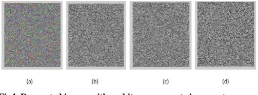
A good encryption algorithm should be sensitive to the encryption keys in process of both encryption and decryption. When encrypt image, tiny change of keys receive two different cipher images and when decrypt image, if we use wrong key we receive different image. Figures 3(a)-(d) shows the decrypted image of pepper with the correct key μ3=1.56.
Fig3. Decrypted image and its components with correct parameters and its components.
Figure 4(a)-(d) shows the decrypted image of pepper with a wrong encryption key μ3=1.56000000000001. So it can be concluded that the algorithm is sensitive to the key, a small change of the key will generate a completely different decryption result and cannot get the correct plain-image.
Fig4. Decrypted image with and its components incorrect parameters
4.3
Correlation Analysis
[image:3.595.319.571.577.670.2]𝑟𝑥𝑦= 𝐷(𝑥) 𝐷 𝑦 𝑐𝑜𝑣 (𝑥,𝑦) (3)
𝑐𝑜𝑣 𝑥, 𝑦 =1
𝑁 𝑥𝑖− 𝐸 𝑥 (𝑦𝑖− 𝐸(𝑦)) 𝑁
𝑖=1
𝐸 𝑥 =1
𝑁 𝑥𝑖 𝑁 𝑖=1
𝐸 𝑦 =1
𝑁 𝑦𝑖 𝑁
𝑖=1
𝐷 𝑥 = 𝑁𝑖=1(𝑥𝑖− 𝐸 𝑥 )2
𝐷 𝑦 = 𝑁𝑖=1(𝑦𝑖− 𝐸 𝑦 )2
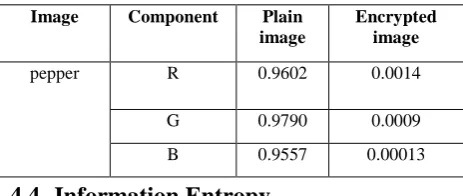
[image:4.595.49.281.307.405.2]Where x, y are gray value of two adjacent pixels. The vertical and diagonal directions results are obtained, they are shown in Table 1. The correlation of two adjacent pixels in plain image closed to 1, while in ciphered image it closed to 0 which demonstrate that the image encryption could effectively resist statistical attack.
Table 1: The correlation test of the components R, G, B of
the plain image and the encrypted image.
4.4
Information Entropy
The information entropy is defined to express the degree of uncertainties in the system [18].Using it to express uncertainties of the image information. The information entropy measures the distribution of gray value in image. If the uncertainty of image is greater, the entropy is bigger and the decrypting process of the image requires more information too. On the contrary, the more orderly of the encrypted image is the smaller of the information entropy. The information entropy equation is written as follows:
H (m)= 𝑃(𝑚𝑖) 𝑙𝑜𝑔21 1 𝑃(𝑚𝑖)
𝑀 𝑖=0
(4) Where M is the total number of symbols 𝑚𝑖, 𝑃(𝑚𝑖) represents
the probability of occurrence of symbol 𝑚𝑖 and the logarithm
bases 2 so that the entropy is expressed in bits. The information entropy of an ideal random image is 8. Table 2 shows that the entropy of encryption image is very close to 8. This means that the encrypted images are close to a random source and the proposed algorithm is secure against the entropy attack.
Table2. Information entropy of original image and decrypted
Image Component Plain image Encrypted
image
pepper R 7.3921 7.9973
G 7.6813 7.9973
B 7.1756 7.9966
4.5
Histogram analysis
The image histogram illustrated how pixels in an image are distributed by graphing the number of pixels at each color intensity level. Figure 5(a)-(c) shows the histogram of plain components R, G, B.
Fig5. The histogram of original image’s components R, G,
and B. (a) The histogram of R component. (b) The histogram of G component. (c) The histogram of B
component.
Figures 6(a)-(c) shows the histogram of encrypted components R, G, and B. The histogram of the cipher image is fairly uniform and significantly different from that of the original image
Fig 6: The histogram of the encrypted image’s components R, G, and B. (a) The histogram of encrypted component R.
(b) The histogram of encrypted component G (c) The histogram of encrypted component B.
4.6
NPCR and UACI Analysis
The measures NPCR and UACI test the different range between two images. NPCR stands for the changing rate of the number of pixels while one pixel of plain image is changed. UACI stands for the average intensity of the differences between the plain image and the cipher image. Calculate
NPCR
R,G,B andUACI
R,G,B by using the following formulas:𝑁𝑃𝐶𝑅𝑅,𝐺,𝐵=
𝐷𝑖𝑗 𝑅 ,𝐺,𝐵(𝑖,𝑗 )
𝑊×𝐻 × 100% (5)
𝑈𝐴𝐶𝐼𝑅,𝐺,𝐵= 1 𝑊×𝐻
|𝐶𝑖𝑗 𝑅 ,𝐺 ,𝐵 𝑖,𝑗 −𝐶′𝑅 ,𝐺,𝐵 𝑖,𝑗 |
255 ×100% (6)
Where W and H are the width and height of the plain image, 𝐶𝑅,𝐺,𝐵 𝑖, 𝑗 and 𝐶′𝑅,𝐺,𝐵 𝑖, 𝑗 are the (i, j) pixel values of the
encrypted image before and after changing the value of one pixel the pixel (i, j) of the plain image respectively. The value 𝐷𝑅,𝐺,𝐵 𝑖, 𝑗 equals zero if 𝐶𝑅,𝐺,𝐵 𝑖, 𝑗 = 𝐶′𝑅,𝐺,𝐵 𝑖, 𝑗 ,
otherwise DR,G,B i, j equal one. In Table 3, NPCRR,G,B is over
99% and UACIR,G,Bis over 33%. These results show that, the
proposed algorithm is very sensitive to tiny changes in the plain image, even if there is a change in only one pixel, the decrypted images is completely different. Thus, the algorithm is robust against differential attack.
Image Component Plain
image
Encrypted image
pepper R 0.9602 0.0014
G 0.9790 0.0009
Table3. NPCR and UACI results
Image Proposed algorithm
R G B
Pepper NPCR
%
99.6674 99.6338 99.5712
UACI %
33.6665 33.5003 33.4723
4.7
PSNR analysis
The Peak Signal-to-Noise Ratio (PSNR) reflects the encryption quality. The Mean Square Error (MSE) is the cumulative squared error between the original and the decrypted image. The lower value of MSE means lesser error.
𝑀𝑆𝐸𝑅,𝐺,𝐵=
𝑃𝑅 ,𝐺 ,𝐵 𝑖,𝑗 −𝐶𝑅 ,𝐺 ,𝐵 𝑖,𝑗
𝑀𝑥𝑁 𝑗
𝑖 (7)
𝑃𝑆𝑁𝑅𝑅,𝐺,𝐵= 20 ∗ 𝑙𝑜𝑔10( 255
𝑠𝑞𝑟𝑡 𝑀𝑆𝐸𝑅 ,𝐺 ,𝐵) (8) Where 𝑃𝑅,𝐺,𝐵 the original is image and
𝐶𝑅,𝐺,𝐵 is the
encrypted image. The lower value of PSNR is the better encryption quality. The results are showed in table 4.
Table4. PSNR results
Image Proposed algorithm
R G B
Pepper 9.0945 7.7804 7.7578
4.8
Randomness test
The security of cryptosystem has some properties such as good distribution, long period, high complexity and efficiency. In particular, the outputs of the cryptosystem must be unpredictable in the absence of knowledge of the inputs. Recently, the NIST designed a set of different statistical tests to test randomness of binary sequences produced by either hardware or software based cryptographic random or pseudorandom number generators [19]. These tests focus on a variety of different types of non-randomness that could exist in a sequence. We use the NIST tests suite in order to test the randomness of the proposed algorithm. In all tests if the computed P-value is less than 0.01, the sequence is non-random. Otherwise, the sequence is non-random. Table 5 depicts the NIST tests results and illustrates that the image sequences encrypted by the proposed system pass all the statistical tests with high P-values.
Table5. NIST Randomness Tests
Image Test Name P-value
P
ep
p
er
Approximate Entropy 0.817929
Frequency 0.079125
Block Frequency 0.968310
Cumulative sums 0.149466
FFT 0.257962
Linear complexity 0.828726
Run 0.840074
Longest Run 0.166992
Overlapping template 0.137277
Rank 0.611852
Serial P-vaue1 0.672378
Serial P-value2 0.640758
Universal 0.814821
5.
CONCLUSION
In this paper, the security of the system is increased by using two chaotic systems. The proposed system consisted of three phases. In the first phase a new 1-D chaotic map is used to scramble the blocks of image. In the second phase a 2-D logistic map is used to shuffle the position in rows and columns. Finally the 1-D chaotic map is used again to change the values of the pixels. The simulation results show that the correlation coefficient between two adjacent pixels in the cipher image is far less than that of plain image; this indicates that the cipher image has a high performance of resisting statistical attack and high sensitive to security key. The key space of the proposed system is about 10^140, it is bigger than the key space of using only a 1-D chaotic map. The keys space is large enough to resist brute-force attack. 3D logistic map will be used in future work to increase the security of algorithm.
6.
REFERENCE
[1] S. Li, G. Chen, A. Cheung, B. Bhargava, K.-T. Lo, On the Design of Perceptual MPEG video Encryption Algorithms, CoRR abs/cs/0501014, 2005.Encryption Algorithms, CoRR abs/cs/0501014, 2005.
[2] C. Fu, Z. Zhang and Y. Cao, “An Improved Image Encryption Algorithm Based on Chaotic Maps,” Third In-ternational Conference on Natural Computation, Vol. 3, Washington, 2007, pp. 24-27.
[3] S. Li, C. Li, G. Chen, N.G. Bourbakis, K.T. Lo, “A general quantitative cryptanalysis of permutation-only multimedia ciphers against plaintext attacks”, Signal Processing: Image Communication 23 (3) (2008) 212– 223
[4] Xin Zhang, Webin Chen,”Anew Chaotic Algorithm For Image Encryption”, pp.889-892 IEEE ICALIP 2008. [5] G.R. Chen, Y.B. Mao, and Charles K. Chui, “A
symmetric image encryption scheme based on 3D chaotic cat maps”, Chaos, Solitons & Fractals, 2004, pp. 749-741.
[6] Y.N.SI, B.S KANG, “Digital Image Scrambling Based on Improved Arnold Transformation”, Chinese Comp. Technology and development, 2008, pp.74-79.
[7] Y. Wang, Z.W. Zhao, and L.L. Zou, “A Fault-tolerable Encryption Algorithm for Two-dimensional Digital Image”, 2007 2nd IEEE Conference on Industrial Electronics and Applications, 2007, pp. 2737-2741. [8] Hongjuan Liu, Zhiliang Zhu, Huiyan Jiang, Beilei Wang.
“A Novel Image EncryptionAlgorithm Based on Improved 3D Chaotic Cat Map”, The 9th International Conference for Young Computer Scientists, 2008. [9] K.Sakthidasan Sankaran and B.V.Santhosh Krishna,” A
Journal of Information and Education Technology, Vol. 1, No. 2, June 2011.
[10] LIU Xiangdong, Zhang Junxing, Zhang Jinhai, He Xiqin,”Image Scrambling Algorithm Based on Chaos Theory and Sorting Transformation”.IJCSNS International Journal of Computer Science and Network Security, VOL.8 No.1, January 2008.
[11] Qais H. Alsafasfeh, Aouda A. Arfoa,” Image Encryption Based on the General Approach for Multiple Chaotic Systems”, Journal of Signal and Information Processing, 2011, 2, 238-244.
[12] H. Zhang, X.F. Wang, Z.H. Li, and D.H. Liu, “A Fast Image Encryption Algorithm Based on Chaos System and Henon Map”, Chinese Journal of Computer Research and Development,2005,pp.2137-2142.
[13] X.J. Li, J.H. Peng, and N. Xu, et al. “Image Encryption Algorithm Based on 2D Hyper chaotic Sequences”, Journal of Image and Graphics, 2003, pp. 1172-1177. [14] Sudhir Keshari, 2Dr. S. G. Modani,” Image Encryption
Algorithm based on Chaotic Map Lattice and Arnold cat map for Secure Transmission”, IJCST Vol. 2, Issue 1, March 2011.
[15] Guoji Zhang a, Qing Liu b,,” A novel image encryption method based on total shuffling scheme”, Optics Communications 284 (2011) 2775–2780.
[16] Xingyuan Wangn, LinTeng,XueQin,” A novel colour image encryption algorithm based on chaos”, Signal Processing 92 (2012) 1101–1108.
[17] N. F.Elabady , H. M.Abdalkader , M. I. Moussa and S. F. Sabbeh, ”Image Encryption Based on New-One dimensional chaotic Map”, Second International Conference on Engineering and Technology ,GUC,Egypt,2013.
[18] Wang Y, Wong K-W, Liao X, Chen G,”A new chaos-based fast image encryption algorithm”, Applied Soft Computing , Volume 11 Issue 1, January, 2011 [19] Rukhin, A. et al. (2010b). A Statistical Test Suite for