Shape distortion and air gap formation during continuous
casting.
DELMONT, Andres Emilio.
Available from Sheffield Hallam University Research Archive (SHURA) at:
http://shura.shu.ac.uk/19549/
This document is the author deposited version. You are advised to consult the
publisher's version if you wish to cite from it.
Published version
DELMONT, Andres Emilio. (1985). Shape distortion and air gap formation during
continuous casting. Doctoral, Sheffield Hallam University (United Kingdom)..
Copyright and re-use policy
794846601 0 TELEPEN
Sheffield City Polytechnic Library
REFERENCE ONLY
'
"S2oSS
Fines are charged at 50p per hour
ProQuest Number: 10694430
All rights reserved
INFORMATION TO ALL USERS
The quality of this reproduction is dependent upon the quality of the copy submitted.
In the unlikely event that the author did not send a com plete manuscript and there are missing pages, these will be noted. Also, if material had to be removed,
a note will indicate the deletion.
uest
ProQuest 10694430
Published by ProQuest LLC(2017). Copyright of the Dissertation is held by the Author.
All rights reserved.
This work is protected against unauthorized copying under Title 17, United States C ode Microform Edition © ProQuest LLC.
ProQuest LLC.
789 East Eisenhower Parkway P.O. Box 1346
SHAPE DISTORTION AND AIR GAP FORMATION DURING CONTINUOUS CASTING
by
Andres Emilio Delmont Mauri
This thesis is submitted in part fulfilment of the requirements for the Degree of Doctor of Philosophy of the Council for National Academic Awards. The work was carried out at Sheffield City Polythecnic, Department of Metals and Materials Engineering, in collaboration with British Steel Corporation.
PREFACE
This thesis is submited in part fulfilment of the requirements for the Degree of Doctor of Philosophy of the Council for
National Awards. The research described was carried out during the period from January 1979 to January 1985 in the Department of Metals and Materials Engineering (formerly Department of Metallurgy) at the Sheffield City Polythecnic. No part of this dissertation has been submitted for a degree at any other
University or College.
During the period of this work the author attended the following lectures which constituted part of the MSc in Metallurgical Process Management at the Sheffield City Polythecnic *.
Module I Process Metallurgy.
Mechanical Metallurgy. Advanced Thermodinamics.
Module II Computational Methods and Numerical Analysis.
Accountancy.
Micro-Economics and Financial Control.
Module III High Strength Steels.
Ironmaking.
Heat treatment and transformations. Secondary Steelmaking.
Oxigen Steelmaking.
Metals and competitive Materials
Module IV Case Studies in the subject areas of: Heat Treatment and Transformations.
Ironmaking.
Healths Safety in the Continuous Casting Steels. (Appendix 3 of this dissertation) of The Candidate's performance during the above-mentioned courses has been satisfactorily assesed by means of specific
ACKNOWLEDGEMENTS
I would like to thanks my supervisor Dr A W D Hills for the guidance he has given me during the course of this work.
Especial thanks go to Ms L Pearse, Ms D Cosham, Ms P Oldfield, Mr R day, Mr D Rimmer, Mr D Latimer, Mr B Taylor, Mr R Grant Mr N Dziemidko, for their help and frienship. The suggestions and assistance of Mr M Muldownie, Mr R Daniel , Ms D Mullen Mr J Bradshaw, Mr R Dimberline, Mr P Fletcher, Mr J Ross-Smith. Mr R Thomas, Mr B Palmer, Mr P Slingsby, Mr B Dodds, Mr G Gregory, Dr F B Pickering, Dr A J Fletcher and
Dr G Briggs, from the Department of Metals and Materials
Engineering, Dr A C Baker, from the Department of Mathematics, Statistics & Operational Research , Dr N W Taylor, from the Department of Civil Engineering, and Dr M S J Hashmi, from the Department of Mechanical and Production Engineering, are
gratefully acknowledged. I would like to thank Dr I G Davies from the British Steel Corporation for his advice. Finally I would like to express my gratitude to my fellow students
Mr J Soady, Mr A Bott. Ms M Staia, Mr J Duncombe, Mr H Cuicas and Mr M Simon for their advice and encouragement throughout this work.
I would like to acknowledge the Consejo Nacional de
SHAPE DISTORTION AND AIR GAP FORMATION DURING CONTINUOUS CASTING by Andres Emilio Delmont Mauri
ABSTRACT
A theoretical model has been developed which relates the buiici-up of stresses in the thin shell of steel solidifying in a
continuously casting mould, to the shape distortion and the
formation of an air gap. The work postulates that the behaviour of this shell can be analysed as that of a flexible structure formed by four elasto-perfectly plastic beams linked by rigid comers. This "box" represents the whole section of solidified shell at a given metallurgical height only if the section is totally detached
from the mould. In general, it represents the detached corner
portions alone. The rest of the shell is assumed to remain clamped against the mould wall by the metallostatic pressure. The thermal contraction of the neutral axis "filament" along the whole shell determines the amount of room which is available for the detached corner portion to distort, and thus also the size of the detached lengths of shell. The mechanical equilibrium of the structure is determined by the combined effect of temperature gradients and metallostatic pressure, by the rigidity condition imposed at the corner and by the flexural characteristics of the shell. The yield stress of the steel is assumed linearly dependent on temperature. The analysis of the shape distortion and air gap formation was
initially informed by the observed behaviour of a partial physical analogue constructed from bi-metallic strips linked by rigid
corners. Thermal moments were induced by immersing this analogue in a water bath at controlled temperatures, and distributed loads were imposed through a system of pulleys. The elastic behaviour of this physical analogue was predicted using basic beam theory. For the analysis of the deformation of a continuously cast
structure, mathematical equations were derived which describe the overall moment and force equilibrium; the elastic and plastic stress distribution across the thickness of the shell; and the force and moment equilibrium within the cross-section of the shell. An equation was derived relating the curvature at any point along the shell to the moment at the corner of the
structure. An iterative procedure was developed to determine the moment at the corner and a Runge-Kutta algorithm was incorporated to integrate the curvature equation. Further equations were
derived which relate the deflection at the corner and the detached length on one side of the section, to the total length of the
other side of the section.
Recent high temperature studies of the mechanical behaviour of steels have been analysed in terms of the theoretical model
developed. The model is able to predict the extent and thickness of the air gaps forming in the corner regions during the casting of billets and slabs and also provides explanation for the
TABLE OF CONTENTS
Page PREFACE
ACKNOWLEDGEMENTS i
ABSTRACT
LIST OF SYMBOLS LIST OF FIGURES LIST OF TABLES CHAPTER 1
INTRODUCTION 1:1
to 1:4 CHAPTER 2
LITERATURE REVIEW
2.1 Gap formation in continuous casting. 2:1
2.2 Empirical evidence. 2:2
2.3 Theoretical models. 2:16
2.4 Mathematical models. 2:20
2.5 Mechanical properties of steels
at high temperatures. 2:26
to 2:33 CHAPTER 3
EXPERIMENTAL DEVELOPMENT OF BIMETALLIC STRUCTURE ANALOGUE 3.1 Stages of development,
Introduction. 3:1
Selection of the bimetal. 3:2
Rigid corner bimetallic structure. 3:9
The use of longer bimetallic strips. 3:18
3.2 Bimetallic structure analogue,
Introduction. 3:47
Description of the apparatus. 3:48
CHAPTER 4
DERIVATION OF THE EQUATIONS FOR THE MATHEMATICAL MODELING OF THE DEFORMATION OF A CONTINUOUSLY CAST STRUCTURE
4.1 Preliminary statement of the model. 4:1
4.2 The overall moment and force equilibrium
equations. 4:11
4.3 The stress d i s t ribution across
the thickness of the beams. 4:17
4.4 Plastic and elastic stress. 4:26
4.5 The cross-section force and moment equilibrium
equations. 4:35
4.6 The curvature as a function
of the moment at the corner. 4:38
4.7 The deflection of the structure. 4:46
4.8 The restraining presence of the mould. 4:52
4.9 Data used for the initial predictions. 4:60
to 4:63
CHAPTER 5
COMPUTER PROGRAM 5 :1
to 5:17
CHAPTER 6 RESULTS
6.1 Preliminary analysis of the
behaviour of the model. 6:1
6.2 Square billets within the mould. 6:17
6.3 Effect of halving the length of corner assumed rigid on the results predicted for
billets within the mould. 6:42
6.4 Effect of reducing the assumed value of the quasi-static yield stress at 1000 degC on the results predicted for billets
within the mould. 6:52
6.5 Effect of doubling the Young's modulus on the results predicted for billets
within the mould. 6:60
6.6 Analysis of off-corner cracking in a slab 6:68
6.7 Analysis of crack progression within the mould
during the casting of square billets. 6:74
to 6:88 CHAPTER 7
DISCUSSION 7*1
7.1 Distortion and stress distribution. 7:4
7.2 The formation and propagation of
longitudinal off-corner cracks. 7:12
7.3 Characteristic behaviour of the model. 7:24
7.4 Effect of the assumptions made. 7:36
7.5 The bi-metallic strips analogue. 7:42
CHAPTER 8
CONCLUSIONS AND FURTHER WORK 8:1
to 8:3 REFERENCES
APPENDIX 1
DERIVATION OF THE EQUATIONS FOR THE MATHEMATICAL MODELLING OF THE DEFORMATION OF THE BIMETALLIC STRUCTURE ANALOGUE. Al.l Characteristics and thermal behaviour
of bimetallic strips. A 1 :3
A l .2 The effect of thermal stress
upon the structure. Al:10
Al.3 The effect of the load
up ~ the structure. .Al:19
to A l .43
APPENDIX 2
BIMETALLIC STRIPS STRUCTURE MODEL COMPUTER PROGRAM A 2 :1
to A 2 :8
APPENDIX 3
CASE STUDY: HEALTH & SAFETY
IN THE CONTINUOUS CASTING OF STEEL A3:1
LIST OF SYMBOLS
a The length of the corner considered rigid, [m]
al Coefficient of thermal expansion of the solid
metal, [°C“^]
c^(u) Coefficient in the linear stress distribution
function = to the stress at the cooling wall at position u, [N.rn- ^]
C2 (u) Coefficient in the linear stress distribution
function = to the stress gradient between the cooling wall and the elastoplastic boundary at position u, [N.rn-^]
c(u) Curvature of the beam at position u, [m~*]
or d2 Lengths of two filaments at different distances
from cooling wall, [m]
E Young's Modulus
f Axial force per unit depth of solidified shell
applied to a node, [N.m- ^]
ft Transverse force per unit depth of solidified shell
applied to a beam at the rigid corner, [N.m ]
g Acceleration due to gravity, [m.s”^]
k Exponent to determine the sign of the plastic
stress, [see page 4:26]
1 The length of the the solidified shell unsupported
by the mould in half the length or width of the ingot cross section, [m]
m Moment per unit depth of solidified shell applied
at a node, [N]
metH Metallurgical height - distance below metal
meniscus, [m]
m(u) Moment per unit depth of solidified shell in the solid shell at generic coordinate u, [N]
* a * Generic corner node of the generic beam (a = 3 ), [(See Pages 4 13-15)]
* c * Generic node at the rigid boundary of the generic beam (c = 1 or 5), [(See Pages 4:13-15)]
n(u) or n Distance across the solidified shell from the cooling wall to the neutral axis at a position u,
[m]
p(u) or p Distance across the solidified shell from the cooling wall to the elastoplastic boundary at a position u, [m]
q Liquid metal pressure exerted on solidified shell,
[N.m” ^]
r(u) or r Radius of curvature of the beam at position u measured from the cooling wall, [m]
so The stress in the solidified shell at the cooling
wall, [N.m- ^]
s(u,v) The stress in the solidified shell at a distance v from the cooling wall- [N.m- ^]
t Thickness of solidified metal, [m]
T Temperature [°C]
Tc The temperature of the cooling wall, [°C]
Ts The solidification temperature, [°C]
T(v) Temperature in the solidified shell at a distance
v from the cooling wall, [ ° C ]
u Coordinate distance along the generic beam from the
corner edge, [m]
v distance across the generic beam from the cooling
wall, [m]
w(u) Deflection of the generic beam at position u, [m]
x,y Coordinates in a system whose origin lies in the
corner when there is no distortion - distances towards the liquid core taken as positive, [m]
Yo Absolute magnitude of the yield stress of the
solidified shell at the cooling wall, [N.m- ^]
Y(v) Absolute magnitude of the yield stress of the
solidified shell at a distance v from the cooling wall, [N.m“2]
ADIMENSIONAL VARIABLES
A Length of the corner considered rigid, [See page 4 41]
Al Coefficient of thermal expansion, [See page 4:41] C Curvature of beam [See page 4-46]
E* Young's modulus, [See page 4:40]
F Force. [See page 4:39]
L Length of the unsupported shell, [See page 4:41]
M Moment. [See page 4:39]
N Position of the neutral axis, [See page 4:41]
P Position of the elastoplastic boundary, [See page
4:41]
Q Liquid metal pressure, [See page 4:40]
S Stress, [See page 4:39]
So Stress at the cooling wall, [-]
V Distance from the cooling surface [See page 4 40]
U Distance from the corner, [See page 4:41]
W Deflection, [See page 4:46]
Yp Stress at the elastoplastic boundary, [-]
SUFFICES
1,2 Related to the two adjacent sides of an ingot when
applied to 1, [-]
1 - 5 Related to the nodes * 1 * to * 5 *, [See Figure 6 on page 4:13]
a„b or c Related to the nodes * a *, [* b * or * c *]
i Related to the side i of an ingot, [-]
ii Related to the adjacent side of the ingot, [-]
SUPERFIX
0,i Superfix relating to the current iteration value of
Lj1 £> T Ut tlLiUKfcb
The figures and pages in each chapter are numbered separately, the page numbers being a two part sequence. The first digit in the sequence represents the chapter number- the second one or two digits represents the page number in the chapter
Explicit reference to the chapter in which a figure appears is not m a d e in this list of figures since the chapter reference is e m b e d d e d in the page number.
Page Figure:
No- Title
2:3 1 Rate of heat transfer from ingot to mould.(4)
2:5 2 Contact sensor pattern and % contact time vs depth, (from L.S.Rudol, ref-11)
2:5 3 Variation in gap size along wide face d^ and nar r o w
face <$2'
2:6 4 Mould heat flux as function of distance from top of
mould for various casting speeds.(19)
2:9 5 Extent of solidification front non-uniformity over
lenght of continuously cast strand.(17)
2:9 6 Coefficient of non-uniformity of thickness (17)
2:9 7 Coefficient of non-uniformity of thickness (17)
2:9 8 Effect of melt flow rate from steel casting nozzle.(17)
2:13 9 Location of thermocouples in copper mould (22)
2:13 10 Chemical analysis, mould-wall temperature and mould heat transfer for the heats investigated.(22)
2:14 11 Effect of carbon content on mould heat-transfer rate continuous casting.(22)
2:14 12 Temperature variation for the thermocouple located 1-1/2 in below the meniscus. (22)
2:15 13 Effect of carbon content on mould friction during continuous casting.(22)
2:15 14 As-cast surface on 0.10% and 0.40% carbon steels that have been shot-blasted.(22)
2:31 2:33 2:33 3:3 3:8 3:9 3:13 3:21 3:23 3:29 3:42 3:43 3:46 3:48 3:49 3:50 3:51 3:52 3:53 3:54 3:55
List of F i g ur e s
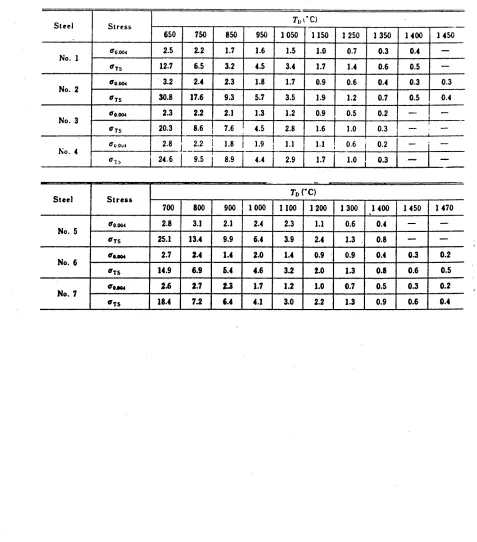
17 Stress-strain curves for n. 2 and n.3 high carbon steels-(52)
18 Dependence of tensile strength on temperature and carbon equivalent-(18)
19 Strain rate dependence of tensile strength at 1150*C for the steels listed in table 1.(52)
1 Comparative deflection curves for telcon medium to high activity bimetals.
2 Maximum loading stress curves.
3 Rigid corner bimetallic structure as assembled for experiment
1-4 Measuring with a fixed ruler.
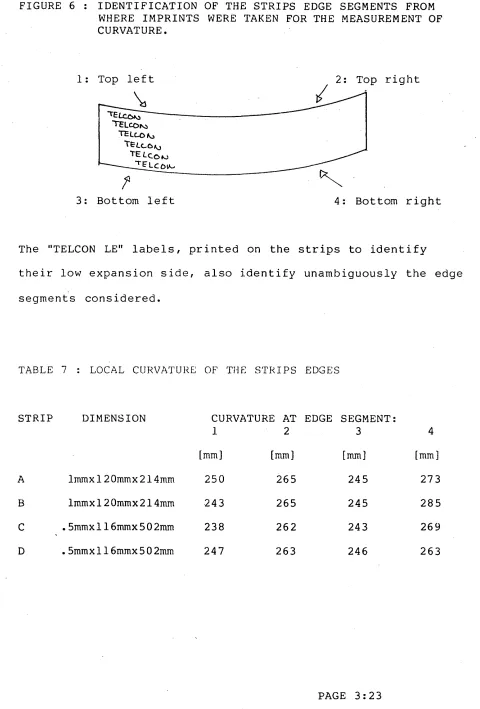
5 Bimetallic strip curved at room temperature. 6 Identification of the strips edge segments from
where imprints were taken for the measurement of curvature.
7 Top view of the bimetallic strips structure used in experiment 4.
8 Deflection of the beam due to thermal stress experiment 4.
9 Deflection of the beam due to both thermal stress and loads at the long beam middle spar.
10 Predicted and experimental results model 2. experiment 4.
11 General view of the apparatus out of the water tank.
12 Top view of the bimetallic strips structure. 13 General view of the apparatus in the water tank. 14 Immersion heater disposition in the water tank 15 Detailed view of the pulley set up.
List of F i g u r e s 3: 57 4:2 4:4 4:10 4:10 4:10 4:13 4:14 4:15 4: 23 4:24 4:25 4:34
6:6
6:76:8
6:9 6:1020 Corner supported on a low friction nylon bush-1 Representation of the cross section of a
continuously cast structure, perpendicular to the direction of casting at a given metallurgical height.
2 Corner section through a solidifying billet or slab.
3 Model representation of a quarter-section
perpendicular to the direction of casting, of a continuously cast structure at a given
metallurgical height.
4 Temperature distribution across the thickness of a beam.
5 Yield stress distribution across the thickness of a beam.
6 Overall equilibrium of the structure. 7 A generic beam.
8 A section of a generic beam.
9 Stress distribution at a generic cross-section. 10 Variation of the stress distribution.
11 Stress distribution and sign of the curvature in situations 10b and lOh.
12 Geometric relation between the length of filaments
at different distances from the cooling wall. 1 Preliminary analysis of the behaviour of the
model: reducing delt in the case of billets with QSYS = 0.2X10“ ® N.m
2 Preliminary analysis of the behaviour of the model: reducing delt in the case of billets with QSYS = 0.3X10“® N.m”2
3 Preliminary analysis of the behaviour of the model: reducing delt in the case of blooms.
4 Preliminary analysis of the behaviour of the model:
Increasing the aspect ratio (Short Face)
6:11 6:12 6:13 6:14 6:15 6:16 6:39 6:40 6:41 6:51 6:52 6:59 6:67 6:71 6:72 6:79
6 Preliminary analysis of the behaviour of the model: Decreasing the thickness t in the case of slabs with delT = 250®C. (Short Face)
7 Preliminary analysis of the behaviour of the model: Decreasing the thickness t in the case of slabs with delT = 250XC. (Long Face)
8 Preliminary analysis of the behaviour of the model: Decreasing the thickness t in the case of slabs with delT = 300®C. (Short Face)
9 Preliminary analysis of the behaviour of the model: Decreasing the thickness t in the case of slabs with delT = 300®C. (Long Face)
10 Preliminary analysis of the behaviour of the model: Decreasing the Young’s modulus in the case of slabs with delT = 300°C. (Short Face)
11 Preliminary analysis of the behaviour of the model: Decreasing the Young’s modulus in the case of slabs with delT = 300°C. (Long Face)
12 Detached length vs billet quarter section length as a function of casting speed and metallurgical
height.
13 Adimensional moment at the corner vs quarter
section length as a function of casting speed and metallurgical height.
14 Adimensional moment at mid-face vs quarter section length as a function of casting speed and
metallurgical height.
15 Effect of halving the rigid corner length on the moment at the corner and the rigid boundary.
16 Effect of halving the corner length on the detached length vs section.
17 Effect of reducing the yield stress on the moment. 18 Effect of doubling the Young's modulus on the
moment.
19 1300 mm x 300 mm slab cast at high speed.
20 1300 mm x 300 mm slab cast at intermediate speed. 21 Detached corner section for 200 m m square billet at
6:80 6:81 6:82 6:83 6: 84 6:85
6:86
6:876:88
7:5 7:6 7:16 7:1722 Detached corner section for 200 mm square billet at a metallurgical height of 0.3 m. cast at 0.06 m.s” l
: initial prediction.
23 Detached corner section for 200 mm square billet at a metallurgical height of 0.6 m. cast at 0.06
m.s-: initial prediction.
24 Detached corner section for 250 mm square billet at a metallurgical height of 0.1 m. cast at 0.06 rn.s-^
: initial prediction.
25 Detached corner section for 250 m m square billet at a metallurgical height of 0.3 m. cast at 0.06 m.s
: initial prediction.
26 Detached corner section for 250 m m square billet at a metallurgical height of 0.6 m. cast at 0.06 m.s”l
: initial prediction.
27 Detached corner section for 250 m m square billet at a metallurgical height of 0.6 m. but out of the mould cast at 0.06 m.s”* : initial prediction. 28/29 Detached corner section for 166 m m square billet
at metallurgical heights of 0.1 and 0.3 m. cast at 0.06 m.s- * : initial prediction.
30 Detached corner section for 166 m m square billet at a metallurgical height of 0.6 m. cast at 0.06 m.s
: initial prediction.
31 Cross-section stress distribution: the formation of an off-corner crack in a 16.6 cm x 16.6 cm billet cast at high speed.
1 1300 m m x 300 m m slab cast at 0.03 m.s""* at a metallurgical height of 0.1 m. thickness and
lengths drawn to the same scale — entire quarter section.
2 1300 m m x 300 m m slab cast at 0.03 m.s- ^ at a metallurgical height of 0.1 m. thickness and
lengths drawn to the same scale - detached corner section.
3 Detached corner section for 250 mm square billet at a metallurgical height of 0.12 m cast at 0.06 m.s“ ^:
Initial prediction.
4 Detached corner section for 250 mm square billet at a metallurgical height of 0.2 m cast at 0.06 m.s“ *:
7:18
7: 22
7:34
7:35
7:36
Evolution of an internal crack in a 250 mm square billet cast at 0.06 m.s-1*
Evolution of an internal crack at the mould exit in a 250 mm square billet cast at 0.06 m.s_j.
Reported values of billet size in relation to casting speed, initial numerical predictions, and effect of adjustments.
Detached corner section for 150 mm square billet at a metallurgical height of 0.12 m cast at 0.06 m.s_^:
7:18
7: 22
7:34
7:35
7:36
Evolution of an internal crack in a 250 mm square billet cast at 0.06 m.s-1*
Evolution of an internal crack at the mould exit in a 250 mm square billet cast at 0.06 m.s_^.
Reported values of billet size in relation to casting speed, initial numerical predictions, and effect of adjustments.
Detached corner section for 150 mm square billet at a metallurgical height of 0.12 m cast at 0.06 m.s_j: Predictions with the thickness adjusted to 0.6 it's liquidus value (with QSYSjqoO degC = 6-5x1 0 7 N.m_2
)-Detached corner section for 122 mm square billet at a metallurgical height of 0.12 m cast at 0-06 m.s_j: Predictions with the thickness adjusted to 0.6 it's
-LIST OF TABLES
The tables and pages in each chapter are numbered separately, the page numbers being a two part sequence. The first digit in the sequence represents the chapter number the second one or two digits represents the page number in the
chapter-Explicit reference to the chapter in which a table appears is not made in this list of figures since the chapter reference is embedded in the page number.
Page Table:
No. Title
2:31 1 Chemical composition of the continuously cast slab
samples tested.(52)
2s32 2 Change of 0.4% flow stress and tensile strength
with test temperature.(52)
3:4 1 Instantaneous deflection constants for TELCON
bi-metals.(TPlAr pg 31)
3:5 2 Mechanical properties of TELCON bi-metals.
(TP1A, pg 12)
3:6 3 Fundamental chartacteristics of TELCON bi-metals.
(TP1A* pg 14)
3:14 4 Experimental and theoretical results* experiment 1.
(deflection of the long beam middle span)
3:16 5 Experimental and theoretical results* experiment 2.
(deflection of the long beam middle span)
3:22 6 Characteristics of the bi-metallic strips curved at
room temperature.(information provided by TELCON metals)
3:23 7 Local curvature of the strips edges.
3:30 8 Experiment 4 results ( 1 mm appreciation).
3:36 9 Experiment 4 results (0.5 mm appreciation).
3:41 10 Experiment 4 results: deflections.
6:21/22 1 A-D Characteristic results for billets in the mould:
Casting speed = 0.01 m.s*”
Metallurgical height = 0 . 1 m
6:22/23 2 A-D Characteristic results for billets in the mould:
Casting speed = 0.01
6:24/25 6:26/27 6:28/29 6:30/31 6:32/33 6:34/35 6:36/37 6:45/46 6:47/48 6:49/50 6:54/55 6:56/57 6:58/59 6:61/62
3 A-D Characteristic results for billets in the mould:
Casting speed = 0.01 m .s-^
Metallurgical height = 0 . 6 m
4 A-D Characteristic results for billets in the mould:
Casting speed = 0.03 m.s
Metallurgical height = 0 . 1 m
5 A-D Characteristic results for billets in the mould:
Casting speed = 0.03 m.s-
-*-Metallurgical height = 0 . 3 m
6 A-D Characteristic results for billets in the mould:
Casting speed = 0.03 m.s
Metallurgical height = 0 . 6 m
7 A-D Characteristic results for billets in the mould:
Casting speed = 0 . 0 6 m.s”-1
Metallurgical height = 0.1 m
8 A-D Characteristic results for billets in the mould:
Casting speed = 0.06 m.s
Metallurgical height = 0 . 3 m
9 A-D Characteristic results for billets in the mould:
Casting speed = 0-06 m.s“*
Metallurgical height = 0 . 6 m
10 A-D Results using halsf Krishnamurthy■ s length
Casting speed = 0.06 m.s
Metallurgical height = 0 . 1 m
11 A-D Results using halsf Krishnamurthy*s length
Casting speed = 0.06
m.s--*-Metallurgical height = 0 . 3 m
12 A-D Results using halsf Krishnamurthy*s length
Casting speed = 0.06 m.s
Metallurgical height = 0 . 6 m
13 A-D Results for a low yield stress steel
Casting speed = 0.06 m.s-^
Metallurgical height = 0 . 1 m
14 A-D Results for a low yield stress steel
Casting speed = 0.06 m.s
Metallurgical height = 0.3 m
15 A-D Results for a low yield stress steel
Casting speed = 0.06 m.s-
-*-Metallurgical height = 0 . 6 m
16 A-D Results for a higher Young's modulus
Casting speed = 0.06 m.s
6:63/64
6:65/66
6:74
17 A-D Results for a higher Young's modulus
Casting speed = 0-06
m.s--*-Metallurgical height = 0 . 3 m
18 A-D Results for a higher Young's modulus
Casting speed = 0.06 m.s
Metallurgical height = 0.6 m
19 Relationship between section length, detached
CHAPTER 1 : INTRODUCTION
From its early days Continuous Casting has represented a challenge for Process Modelling. As with other important
advances in Metallurgy, its i m p lementation can be said to result from trial and error rather than from c o m p r e h e n s i v e
theoretical understanding. Yet, much of the trial and error involved in the successful d evelopment of Continuou s Casting
has been based on physical and m a t h e m a t i c a l models.
The pheno m e n a involved in the process are c o m p l e x and the increased speed of solidification which results in the higher
output of the continuous casting process has lead to a whole range of problems not previously encountered with ingot
casting. Some of these problems are caused by intense stresses which develop within the solidifying shell during
solidification. This current research investigation has focussed attention on the study of these stresses and the resulting defo r m a t i o n and overall me c h a n i c a l behavi our of the solidifying shell in the early stages of solidification.
The great m a j ority of m a t h e m a t i c a l models related to the
Continuous Casting process have been p r i m a r i l y conc erned with
Heat Transfer. It is apparent, however, that any further d e v e l o p m e n t of these models requires analysis of the stresses
involved in the process. This has proven to be p a r t i c u l a r l y
difficult in the early stages of solidification due to the
te m p e r a t u r e and the limited understanding of the c o m p l e x
b ehaviour of the solidifying shell. Although a n u m b e r of m o d e l s of increasing c o mplexity have been developed, the
m e c h a n i s m s by which shape distortion and crack f o r m a t i o n occur are still poorly understood.
A fundamental characteristic of the Continuous Casting strand of w h i c h the p r e v i o u s m o d e l s do not take a c c o u n t is t h a t the
thin shells of metal solidifying along the four sides of the billet cross-section behave together as a flexible r e c t a n g u l a r
structure. Mechanical interactions b e t ween adjacent sides of this structure play an essential role in the d e v e l o p m e n t of the
stresses within the solidifying shell. These intera ctions are p a r ticularly intense because the corners act e f f e c t i v e l y as
rigid hinges.
The model that has been developed in this thesis an alyses the e q u i l i b r i u m of forces and m o m e n t s within this r e c t a n g u l a r
structure formed by the thin solidifying shells at a given m e t a l l u r g i c a l height. It assumes that the solidifyi ng shells behave in essence as a “box" constructed from four e l a s t o
-perfe c t l y platic beams rigidly jointed at the corners.
Previous models (26,27,30) which have analysed the b e h a v i o u r of the thin solidifying shells in terms of beam theory have a s s umed an elastic behaviour of the solid steel and have
failled to consider the interaction b e t ween the sides of the
fixed at the ends
The p r e d ictions of these models are clearly restricted by the
support a s s u m p t i o n s made. A net inward dishing or o u t w a r d bowi n g of the skin is predicted depending on w hich support
a s s u m p t i o n is made. The surface stresses predicted are either tensile or c o m p r e s s i v e along the whole beam.
The second chapter of the thesis contains a survey of both e x p e r i m e n t a l and theoretical studies related to the behaviour of the solidifying metal within the mould of a c ont inuous casting machine.
The next chapter describes a simple physical analogue
constructed using b i m e t a l l i c strips and rigid corners. The d e v e l o p m e n t of this physical analogue and of a m a t h e m a t i c a l m odel based on elastic beam theory to predict its b e h a v i o u r
played an esential role in the research providing a basic
understanding. This e l e m e n t a r y m a t h e m a t i c a l m o d e l is p r e s e n t e d
on appendix 1. the c o m p u t e r p r o g r a m developed to p r e dict the deflection of the bim e t a l l i c strips structure is p r e s e n t e d on
appendix 2.
Chapter 4 is the central chapter of the thesis. It states the derivation of a m a t h e m a t i c a l model to analyse the e q u i l i b r i u m of forces and m o m e n t s with i n the rectangular structure formed by the thin solidifying shells at a given m e t a l l u r g i c a l height. The c o m p u t e r program developed to predict the shape d i s t o r t i o n
of this structure and the distribution of stresses and m o m e n t s
ch a pter 6 and discussed in chapter 7.
CHAPTER 2 : LITERATURE REVIEW
2.1 GAP FORMATION IN CONTINUOUS CASTING
As a process, continuous casting seems to be nearer to an ideal continuous production with precise control than the traditional ingot casting. Better control is possible
during the solidification process, the main variables being controlled in a continuous manner.
The high rates of heat transfer involved, however, give rise to phenomenoma of an intensity not seen before in solidifica tion processes and small changes in the control variables produce quite distinct variations in the properties of the resulting material.
2.2 EMPIRICAL EVIDENCE
Although an important number of papers are related to diffe rent measurements of the gap formation, the information avai lable is quite limited and no numerical data is given of the actual shape of the metal strand in or just below the mould zone.
Evidence has been given, however, that under certain circums tances, an air gap forms which varies in size in both l o n g i tudinal and transverse directions and which is not constant in time (for a given particular distance below the meniscus). The relation between the formation of this gap and its various causes has been roughly established.
The time at which gap forms can be measured in the case of ingot moulds by a method originally used by B.Matuschka (1), a wire is passed through the mould wall and the electrical resistance of the wire is measured between the ingot and a measuring point set in the mould wall. The air gap formation shows itself as a sudden increase in this resistance. Several authors (2,4) used this or similar methods. A.Diener et al (3), in a study of static casting, observed that the gap at the corners of the mould sets in quickly after.the rising steel reaches the measuring position, well before the end of the casting, while gap formation in the middle of the sides follows much later and depends on the height of liquid steel
Another method widely used is to place a number of thermocou ples within the mould and record the variation of the tempe rature as solidification proceeds. The gap formation, or colapse is related to perceptible variations in the cooling rate (4,5,6,7-8,9). K.F.Behrens and H.Weingart (5), observed an interval of rapid temperature oscillation in their measu rements, indicating that in that interval the solidified skin alternately separates from the mould and falls back onto it, i.e., when a gap forms there is a build-up of temperature in the solidified layer which raises its temperature and makes it easily deformable. This cycle is repeated until the ingot skin has attained adequate thickness and strength to resist the ferrostatic pressure.
Although these papers make quite wide interpretations of
their results, their true significance is severely limited by the effect on the mechanical behaviour of the metal of fac tors which they do not take into account. Metal composition, as I will explain soon, is one of these factors.
Heat flow estimation methods have also been used. An example is the work developed by Mackenzie and Donald (4) who explain their result, i.e., the rapid fall observed in the rate of heat transfer to the mould (figure 1), as the separation of
&
the ingot from the mould,— 14-r
1
12
-being caused by expansion*^10-<■ & ft—
y <j O —
of the mould, contraction^^*
6-£ s 4-______________________
of the ingot or by both ° 0 5 10 15 20 25 30
FIG 1: Rate of heat transfer from
In his M.Phil thesis at the Sheffield City Polythecnic (1978) Martinez-Fueyo (10), developed a direct observation method. He used a purpose built mould with one transparent glass wall and three metal walls with integrated cooling chanels. It was observed that the air gap starts to form at the corners of the cast progressing towards the center when it is cooled uniformly and at relatively high rates. Pure tin and 50% lead
tin alloy at some 20 C and 50 C respectively above the solidus arrests were used in these experiments.
If gap formation has been observed in ingot solidification, and a lot of valuable information can be deduced from this, gap formation in Continuous Casting is much more pronounced as is the deformation of the metal. In continuous casting, solidification times are measured in minutes compared with the hours of conventional casting.
The measurement methods used in Continuous Casting are i n . general similar to the methods used for ingot solidification measurements, although problems due to the reciprocating
m ovement of the mould have to be solved and no explanation of how this is done has been found in the literature. It is also possible (11) to make direct measurements of the dimensions of the cast structure as it comes out of the mould. But, reading the papers, it is difficult to asess the reliability of the results given.
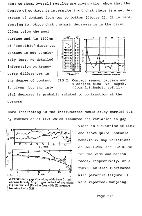
contact between the mould walls and the metal surraces adja cent to them. Overall results are given which show that the degree of contact is intermitent and that there is a net d e crease of contact from top to bottom (figure 2). It is inte resting to notice that the main decrease is in the first 200mm below the pool
165* 24" 32' 4 0 ' 48"
O•o
o;o ©jo o o o|o 0-0 olo olo o|o 0(0 olo o|o 0*0-0(0 oojoo 900 1 0 0 0
9 0 0 o o o
9 0 0 *0 0 0
A T
Narrow
surface and, in 1200mm of "sensible" distance, contact is not comple tely lost. No detailed information on trans verse differences in
the degree of contact FIG 2: Contact sensor pattern and % contact time vs depth,
is given, but the ini- (from L.S.Rudoi, ref.11)
tial decrease is probably related to contraction- at the corners.
More interesting is the instrumented-mould study carried out by Roztkov et al (12) which measured the variation in gap
width as a function of time
1 2 3 4 5 6 7
T, min 8 S 10
50< i
—---—--- - i i t
o'*
r*
f
' o 1♦
1 i i
2 F IG 3 ;
4 6 6
I, min 10 12
i a Variation in gap size along wide face 6 ! and I narrow face 62; b hydrogen content of gap along I (1) narrow and (2) wide face with (3) average
[image:33.612.65.554.15.762.2]tests confirmed the presence of C02, 02, CO, N2 and H2 in the gases. In a related study, Akimenko et al (14) observed that the composition of hydrogen in the gas is a m a x i m u m as the lubricant is first introduced, 45-55%, but that the average composition during casting is closer to 10-20%.
Although the influence of the hydrogen atmosphere in the gap on the heat transfer, and thus on the mechanical behaviour of the metal, is not made evident from these papers, but rather acepted as a fact, several other papers show how important it
is and its importance is readily accepted in today's indus trial practice. Charles R.Taylor, in a 1975 review on conti nuous casting (21), refers to some measurements made by Volk and Wunnenberg from Mannesman in a mould specially designed for the purpose of the mean heat flux in the interface at different levels. This mould has 8 different horizontal chan nels of water.
I 1400 Measuring the water flow and / the change in temperature (in lcj
~ f \ = . I
! ~ \ ~ ’
casting speed, mmiri ~ 0-4
0 6
a similar way as has been dones ^lOOCt-1,»/ for ingot moulds), they esti-j o
! u-mated the heat flux in each of ^ 8 levels. As could be expected the heat flux varied with
depth and they also found that the relation between heat flux and depth varied with the cas ting speed (figure 4).
y 600
200
200 400 600 800
DISTANCE FROM TO? EDGE OF MOULD, mm
auc iuttecisc xu neat transrer cowards the bottom of the mould
is related to the influence of the gas atmosphere in the gap. Jacobi (16), investigated the influence of different gas
atmospheres, reporting that high leves of H2 will result in faster cooling rates.
Taylor relates the presence for hydrogen in the bottom part of the mould with the disociation of water coming up from the top sprays of the secondary cooling zone.
Klipov et al (16), report a higher upper-mould heat flux with oil than with mould powder which is probably also due to an hydrogen-rich atmosphere resulting from the breakdown of the oil. The injection of hydrogen into the gap increases the heat transfer rates as K.Cliff & R.Dain (17) have shown.
However, because the presence of hydrogen is normally related to breakdown of the lubricant film, erratic variations in temperature can be produced.
Now, observing fig. 3, which reviews Rozhkov et al work (13), the oscilations in gap thickness shown do not seem to be
related to any oscilation in the level of hydrogen present. There is, however, a net variation of the hydrogen content in the 12min period considered and it could be said that a
enough s a m p l e s w ere taxen, d u c tnis is not tne explanation.
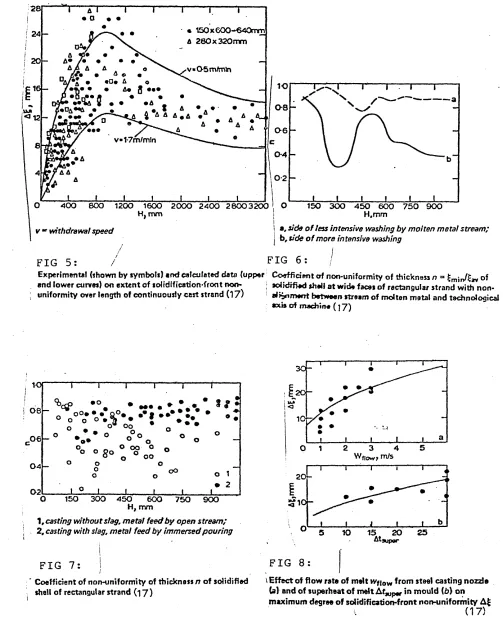
V.A.Ul'yanov et al published a paper on the non-uniformity of the solidification front in continuous casting strands (19), which gives further clues. There is a strong interdependence between the width of the gap, its non-uniformity and the non uniformity of the solidification front. One of the factors which affect uniformity is the disturbing effect of the stream of molten metal. Depending on the casting method and the flow rate of the molten metal, the flow currents extend to a depth of l-2m, while the zone of maximum rates of the circulating currents, which wash the shell being formed, are found at a distance of 0.3-0.8m from the meniscus (that is, in Soviet practice). In this zone, the solidification front is subjected to melting and erosion, with particular intensity,. Non
uniformity of the solidification front occurs as a result of non-alignment between the molten stream and the technological axis of the machine (figures 5,6,7,8 on the next page).
Another major reason for the non-uniformity of solidification is the non-uniformity of the heat extraction around the peri meter of a continuous casting strand, which is, of course not only related to the gap formation but also to:
* non-uniform shrinkage of individual regions of the solidifying shell.
* appearance of additional thermal resistances in the form of lubricant, oxides, slag particles.
* distortion of the mould.
• 150 k GOO—640mm
A 280x320mm
v«05m/mtn
4 A a a#a
1-7m/mln
400 800 1200 1600 2000 2400 28003200
H, mm
v m withdrawal speed
150 300 450 600 750 900
H.mm
i
| a, side o f less intensive washing by molten metal stream;
I b, side o f more intensive washing
FIG 5: FIG 6:
Experimental {shown by symbols) and calculated data (upper Coefficient of non-uniformity of thickness n = of 1 1 - _______________ \ a. . ^i:j i/i___ __________________________________; _____ i i j * r ? . . . . . ' s m i r r s w
and lower curves) on extent of solidification'front
non-uniformity over length of continuously cast strand (17) aJrjfiment between stream of molten metal and technologicalsolidified shell at wide faces of rectangular strand with non-axis of machine (] J )
10f
• o
i 0 8 •
oo oo
0 4 OO
02
150 300 450 600 750 900
H, mm
1, casting without slag, metal feed by open stream; 2, casting with slag, metal feed by immersed pouring
FIG 7:
j
Coefficient of non-uniformity of thickness n of solidified
shell of rectangular strand (17)
3 0
-20“
5
0 1 2 4
20
-10
-20 25
FIG 8
1 Effect of flow rate of melt Wfjow from steel casting nozzle (a) and of superheat of melt At^p* in mould (b) on maximum degree of solidification-front non-uniformity A£
[image:37.623.56.559.50.673.2]* thermal stresses and coarse scratches or dents in the walls (which will deform both or one of the mould and the strand).
* locally varying heat fluxes (associated with the water cooling channels.
* varying flow rates of the water in these water cooling channels.
* non-optimal withdrawal speed.
It has been said (16) that data from numerous experimental investigations and from mathematical modelling indicates that raising the withdrawal speed for 600-640xl50mm strands from 0.5 to 1.1 m/min reduces "A^ax", the maximum non-uniformity, (see figure 6) by a factor of 1.5-2, while a further increase from 1.1 to 1.7 m/min reduces "A^ / by only 5-10%.
There is a close relationship between the casting speed and the breakdown of the lubricant, as H.Takeuchi et al point out (17). Data collected by Gray & Marston, Wyckaert and H.Nakata (refered by 17) show that the velocity of casting correspon ding to a minimum incidence of cracking varies inversely with
the viscosity of the lubricant used. A.W.D.Hills points out a relationship between the lubricant viscosity, the casting speed and the lubricant thickness (18).
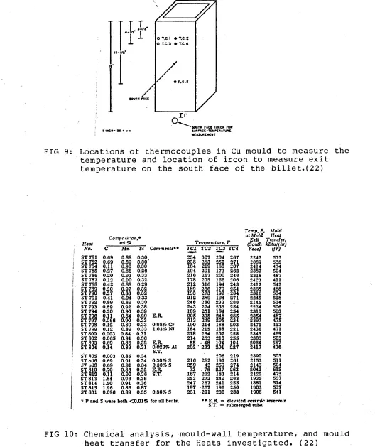
result of the important experimental work they carried out.
A total of 30 heats was cast on a bench-scale caster with steels of 10 different carbon contents (see figures 9 & 10). The mold was stationary. Most of the necessary technical data is given.
To study the macroscopic solid-liquid interface of the soli difying skin, unsolidified steel was emptied from the casting by means of a controlled breakout technique. This technique consisted of burning a hole in the solidified steel skin 1.8m below the mold. After the unsolidified steel flowed out, the shell was withdrawn and cut longitudinally to permit examina tion of the solidified skin. Transverse and longitudinal
sections were taken from the completely solid sections of the billets and etched with hot HC1 to reveal the grain structure The outer surface was shot blasted to remove scale, so that the surface roughness could be examined and the surface could be rated for pinholes.
The technique of controled breakouts (22,23) seems to give the best results for measuring the shell thickness. However-since a finite time elapses while the unsolidified steel is being emptied, the thickness measured is always bigger than the original and this difference increases towards the point where it is being emptied. It should be possible to recognise or estimate this latter skin, although no mention is made of such an estimate in the literature. In any case the errors
mecnoas or measurement.
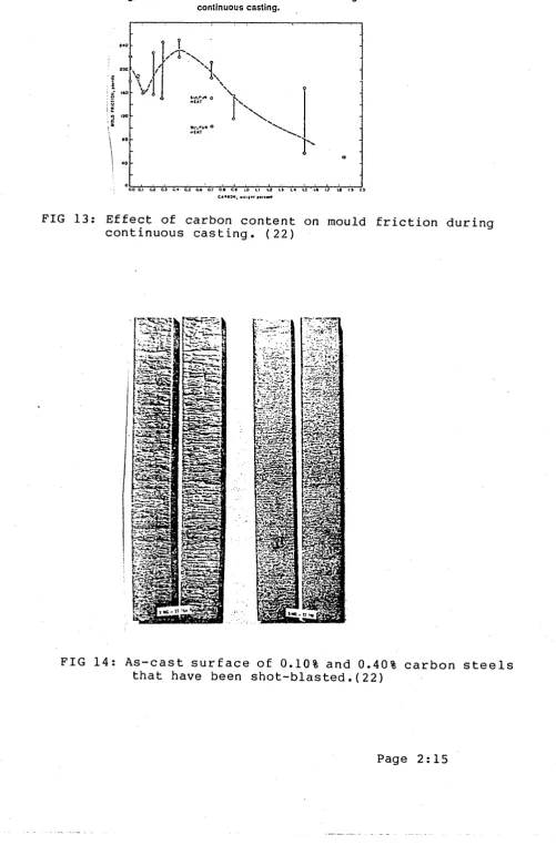
The most interesting result reported by Singh and Blazek (22) is their observation of the change in behaviour that occurs on approaching the 0.1 carbon content in the steel (figures 11, 12, 13, 14). This could explain the differences in results found in comparing previous measurements, which in fact become meaningless when the carbon content is not specified.
The effect of mould reciprocation has, in general, been
avoided in the available literature, although some reference is found in USSR articles in relation to the development of special mould designs to "...avoid skin defects and improve the heat transfer uniformity." (24,25).
The results found by Singh and Blazek for the effect of carbon content on friction in the mould vary greatly and do not seem very reliable (figure 13). Other conditions, not taken into account, might have changed. But it does seem that this factor does not determine the roughness observed at 0.1C which contrasts with the relative smoothness observed at
other carbon contents (figure 14).
Singh and Blazek suggest that the solidified skin is stressed between the shrinking forces due to the change of state
• l/li" FROM INNCR SURFACE
OT.C.I • T.C.2 O T.C.3 • T.C.4
is*
• T .C .S
SOUTH FACE
FIG 9: Locations of thermocouples in Cu mould to measure the temperature and location of ircon to measure exit temperature on the south face of the billet.(22)
Heat Coinpc>*it''on,*tct ft Temperature, F
Temp, F, at Mold Exit (South Face) Mold Heat Transfer, kB tu/ihr) (ft*)
No. C M n Si Comment*** T C I TC2 TC3 TC4
! ST 781 0.69 0.88 0.30 234 307 204 267 2242 532
i ST 782 0.69 0.89 0.30* 238 283 252 271 2089 528
I ST 784 0.11 0.90 0.30 184 219 180 207 2414 434
ST 785 0.27 0.86 0.26 194 291 173 262 2387 504
ST 788 0.20 0.93 0.33 216 267 200 246 2318 487
ST 787 0.12 0.90 0.32 178 205 168 206 2423 411
ST 788 0.42 0.88 0.29 212 316 194 243 2417 542
ST 789 0.20 0.97 0.32 189 266 179 254 2365 488
ST 790 0.27 0.83 0.32 193 273 197 284 2316 534
ST 791 0.41 0.94 0.33 212 289 194 271 2245 518
ST 792 0.89 0.89 0.30 246 280 233 266 2145 524
ST 793 0.89 0.92 0.38 243 274 235 254 2224 506
ST 794 0.20 0.90 0.39 189 251 184 254 2310 503
ST 796 0.11 0.84 0.29 E.R. 205 235 248 285 2354 487
ST 797 0.066 0.90 0.33 213 249 205 234 2397 475
ST 798 0.12 0.89 0.33 0.98% Or 190 214 188 203 2471 413
ST 799 0.12 0.89 0.33 1.03% NJ 184 215 188 221 2436 471
ST 800 0.003 0.84 0.31 218 264 207 258 2345 469
ST 802 0.065 0.91 0.36 214 252 210 255 2305 505
ST 803 0.69 0.86 0.32 E.R. 55 - 4 8 104 104 2064 567
ST 804 0.14 0.89 0.31 0.023% Al
S.T. 202 233 201 227 2417 436
ST 80S 0.003 0.85 0.34 206 219 2390 505
ST 806 0.69 0.91 0.34 0.30% S 216 282 197 261 2152 511
| JT o08 0.69 0.91 0.34 0.30% S 259 42 259 274 2145 504
ST 810 0.70 0.86 0.32 E.R. 73 . 76 227 263 2042 615
ST 812 0.11 0.90 0.36 S.T. 167 202 183 214 2122 472
ST 813 1.84 0.96 0.38 253 272 249 263 1935 523
ST 814 1.50 0.91 0.36 247 267 241 255 1881 514
ST 815 1.96 0.86 0.87 197 -267 196 250 1902 527
ST 831 0.096 0.89 0.35 0.30% S 231 291 230 283 1908 541
* P and S were both <0.01% for all heats. • • E.R. *»
S.T. = submerged tube.elevated ceramic reservoir
[image:41.613.24.552.11.640.2]«2 <C
u U. «az
«c
4 6 0
a
o
a + S7UCY AT PILO T P L A N T
FIG 11: Effect of carbon content on mould heat-transfer rate during continuous casting (22).
1 1 ' ' 3 ; j — I—
...i ! ' ■ 1
! i . ! i 1
' . , / V: v mAtt) /—\v I — r / —: a —inr— M-i V P t ^ \i■ w v
.... i i ■ i
» i ' ! 1 I ' i
. > ! ; : • 1 1 - CARBON|
i i 1 i i |
--- 1--- 1--- !--- i - l --- 1---" J .1
ii
---1— |--- 1 |
---1 i ! 1 A» --- .—
---rT ■ i A - \ i r .r V/ i i i i t 1 i
i i---1---i— i ■---.. 1 --- --- ...1 ... ! i
1 <. I I ! t CARBON --- !---!---i---i . w v. ! 1
- ---!---I
— -■I i : n i i
[image:42.614.57.559.18.755.2]Fig. 7— Effect of carbon content on mold friction during continuous casting.
£
2a
i
FIG 13: Effect of carbon content on mould friction during continuous casting. (22)
[image:43.615.49.551.12.795.2]2.3 THEORETICAL MODELS
Several theoretical models have been developed to describe the behaviour of the metal surface during solidification. The lack of data has made it difficult to acheive satisfactory descriptions, but some growth of understanding of the pheno menon! involved has been acheived. I want to describe here briefly the main models that have been put forward and give some opinion on them.
The model developed by Savage (26) in 1962 consists of 4 beams simply supported with the Young's modulus being taken as
constant up to the melting point of the steel. Purely elastic behaviour of each of these beams is assumed. The beams tend to bow concavely towards the liquid core under the action of the thermal stresses originating from the temperature gradient throughout the shell. However, the beams cannot bow until the ferrostatic pressure is overcome by thermal stresses in the solidified shell and the time when this occurs is taken as the time at which the air-gap forms. The model first assumes the modulus of elasticity to be independent and then dependent of
temperature.
Tien and Koump (27) advanced Savage's model (26). By assuming the solidified skin to be an assembly of four separate beams, each behaving elastically, they calculated the stress
, - cniC"R:n6^ries of the beam surface temperature and for di^-<4
. , , . , • . v.v^t^^ure ^dp«ndent
the beam. Their model assumes a -linear ^
point OS; tho Young's modulus which is nil at the melt*hJ
f4Upport<^d bt»am and material. They consider two cases: a s i ^ ^ ^
a built-in beam. They found, for both ess< ' ‘ displacement.
^ dhangea from a
For simple .upport.d b.... tb« a‘*pl’“ * 'p o . l t W . d o . . « ^ a
after, i.e., the beam changes from a con" shape as solidification proceeds.
. POsit‘*lva,
For a built-in beam the displacement is < ^ ^
i.e., the shape of the beam is convex tO>-^ ^ ^
as solidification proceeds. The final ^ ^ ^
supported beam that this model predicts Savage (26).
t m ||;led layer does not
Weiner and Boley (28) assume that the so. ^ ^
bend, a n d that there are no external £ot<-^' ^
axial direction or at the corners. f l o w i n g Idealised
assumed to be independent of plastic s t r * - ^ ^ ^
plastic theory and as the elastic portlo" ^ Klanto_ included in the analysis, they named the <
Perfectly Plastic.
lav er wa « t.-p.t.tdt. di.trlbotio,, W tt. » U • a c Q n M i i w » * . » to b« , W . n by tb. »— .nn .oWtlob, ^ ^ ^ ^
external surface temperature. This i m p U d „At.ure drrir.
a r °P at