“Study on Effectiveness of Automatic Sliding Gate to Control Backwater”
Noor Azim B. Kamaruddin a, Dwi Tjahjanto b
Department of Water and Environmental Engineering, Faculty of Civil and Environmental Engineering, Universiti Tun Hussein Onn Malaysia
a Research Work Masters Student b Supervisor
Abstract
Automatic sliding gate is a control structure which can work by its self without an operator. The application of automatic sliding gate is wide; however one of the most important applications is for controlling flood and inundation problems in flat urban area which are caused by backwater from the main-drain/river that flows back to the drainage area. Currently, the automatic sliding gate equipped with pump, sensor and motor is being constructed in a scaled physical model in the Laboratory of Fluid Mechanics of UTHM. This model will be used to find the effectiveness of the mechanism of automatic sliding gate to control backwater.
Keywords: Automatic sliding gate; backwater control, flat urban area; physical model
1. Introduction
One of the current problems in flat or plain urban area like Kuala Lumpur, Johor Bahru, Batu Pahat, Malaka, Seremban and many other cities are flood and inundation which are caused by backwater from the main-drain or river that flows back to the drainage area. More even for the area nearby coastal, flood and inundation will be worse when tide is coming in. Backwater problem happens when the head of water in the river/channel is low compared to the main-river/sea level. This problem makes the river/drainage channel flow sluggish and induces backwater and overflow to the lower areas.
One of the most accurate structures for controlling backwater problem in flat
word the sensor system working in order, and c) the capability of pump to deliver water from upstream to downstream of channel through the pipe system.
2. Automatic Sliding Gate
Automatic sliding gate is a hydraulic structure used to control water level and also control backwater in a channel or river. Automatic sliding gate will be located near the mouth of channel or river which is connected with main-river/sea. This gate contains of sliding gate as the main structure and also pumping system, belt and motor system and sensor system as the component structures.
2.1 Structure of Sliding Gate
Sliding gate is the simplest type of flat gate which is largely used as a control device in irrigation canal, reservoir spillway etc. It consists of a gate that slides along the side guides embedded or fastened to the concrete. The leaf is provided with sliding surfaces, usually metallic, which is under tight contact at the bearing surface act as seals. Slide gate requires little maintenance because its operation is safe. Other distinguished characteristics of the slide gates are the uniform transmission of the hydrostatic load to the concrete and the absence of vibration in partial openings due to the large friction force developed between the sliding surfaces (Erbisti, 2004).
In this study, the equation that is used to find the capability of sliding gate structure to handle the water thrust force of backwater that acting on that gate are shown below (Erbisti, 2004):
a) Calculate the water thrust acting on the skin plate for the various gate-opening positions.
The resultant water thrust will then be,
(
2 2)
J
M γB H h
2 1 W W
W = − = −
Where:
WM = the water thrust (upstream)
WJ = the water thrust (downstream) =
γ Specific weight of water =
9.81kN/m3
B = span of side seals
H = maximum headwater on sill.
b) Calculate the skin plate bending stresses from the water pressure with the theory of plates based on the theory of the elasticity, through the formula
2 2 t a p 100 k
σ=±
Where:
k = non-dimensional factor
p = water pressure relative to the module center
a = minor support length t = plate thickness.
c) Calculate the maximum deflection occurs at the center of the plate, and it is given by:
3 4 t E a p α f = Where:
E = modulus of elasticity =
α coefficient as a function of the plate dimensions.
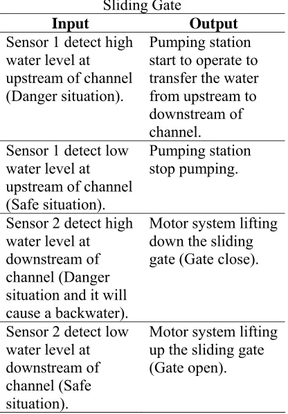
2.2 Sensor System
Table 1: Inputs and Outputs of Automatic Sliding Gate
Input Output Sensor 1 detect high
water level at upstream of channel (Danger situation).
Pumping station start to operate to transfer the water from upstream to downstream of channel. Sensor 1 detect low
water level at upstream of channel (Safe situation).
Pumping station stop pumping.
Sensor 2 detect high water level at downstream of channel (Danger situation and it will cause a backwater).
Motor system lifting down the sliding gate (Gate close).
Sensor 2 detect low water level at downstream of channel (Safe situation).
Motor system lifting up the sliding gate (Gate open).
2.3 Pumping System
Pumping system is another important part in the automatic sliding gate system to control backwater. It is because when backwater problem happens, the sliding gate of automatic sliding gate will be closed to prevent backwater from the main-river flows back to drainage area. So, the pumping system will transfer the water in the upstream to the downstream area of sliding gate through the pipe system to avoid water level in upstream area increase over the danger limit which can cause overflow.
2.4 Belt and Motor System
Belts are used in conveying systems and in the transmission of power over comparatively long distances. It often happens that this element can be used as a replacement for gears, shafts, bearings and other relatively rigid power transmission device. In many cases, their use simplifies the design of a machine and substantially
reduces the cost. In automatic sliding gates system, belt and motor systems is used to lift up and down the sliding gate.
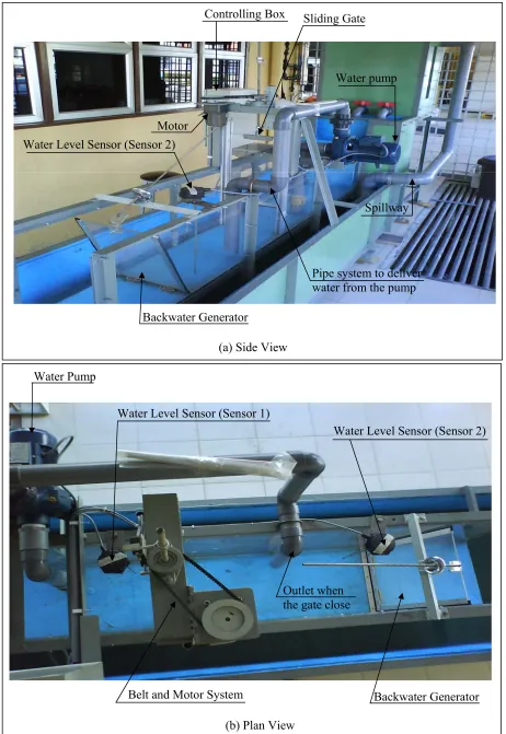
3. Physical Model of Automatic Sliding Gate
The physical model of automatic sliding gate is almost complete to be set up in the Laboratory of Fluid Mechanics of UTHM. The design is based on the method of Distorted and Undistorted Models of Hydraulic Scale Models. This model will be used to find its effectiveness to control backwater. Figure 1(a) and 1(b) shows the arrangement of the model. In this study, the effectiveness of mechanism of automatic sliding gate to control backwater will be tested that is dependent on a) the capability of sliding gate to handle the water thrust force of backwater and close and open the gate automatically when it is required, b) the capability of sensor system to produce a correct output or in other word the sensor system working in order, and c) the capability of pump to deliver water from upstream to downstream of channel through the pipe system. A detail observation and analysis will be done to find the size of various prototypes that can be used as a guidance to construct automatic sliding gate in various sizes.
4. Conclusion
The model not yet runs as the plan. However, a simple running has been done on the model, and the result can be concluded as follows:
1) Sliding gate has enough capability to handle the water thrust force of backwater.
2) Sensor systems have capability to produce a correct output or in other word the sensor system working in order.
3) Pump has capability to deliver water from upstream to downstream of channel through the pipe system. 4) The system of automatic gate is
any program for operation. The set up is just to select between automatic operation and manual operation.
Reference
Bankston J. D., Jr. and Baker F. E. (1994), “Selecting the Proper Pump and Piping System”, Southern Regional Aquaculture Center, SRAC Publication No. 372 and 373.
Erbisti P. C. F. (2004), “Design of Hydraulic Gates”, A.A. Balkema Publishers / Lisse / Abingdon / Exton (PA) / Tokyo.
Rahman A. Roslan, Ismail C. Abas C., Abdullah Y. Mohd (2001), “Mekanik Mesin Teori, contoh Penyelesaian dan Masalah Edisi Ketiga”, Penerbit UTM, Johor, Malaysia.
Backwater Generator Water Level Sensor (Sensor 2)
Sliding Gate
Water Pump
Controlling Box
(a) Side View
Water Pump
Water Level Sensor (Sensor 1)
Water Level Sensor (Sensor 2)
Belt and Motor System Backwater Generator
[image:5.612.78.540.64.735.2](b) Plan View
Figure 1: Physical Model of Automatic Sliding Gate Outlet when
the gate close
Spillway Water pump
Motor