Artificial Neural Network Control of Permanent
Magnet Synchronous Motor
Mahmoud M. Saafan, Amira Y. Haikal, Sabry F. Saraya, Fayez F.G. Areed
Computer and Systems
Engineering Department, Faculty of Engineering Mansoura University, Egypt.
ABSTRACT
This paper presents a neural network controller for permanent magnet synchronous motor (PMSM). The neural controller is used for torque ripple minimization of this type of motors. Two methods of neural controller design are used. The first method is based on two loop controllers (current controller and speed controller). The second method is based on estimation of torque constant and stator resistance in PMSM. The q-axis inductance is modeled off-line according to q-axis stator current. The neural weights are initially chosen small randomly and a model reference control algorithm adjusts those weights to give the optimal values. The neural network parameter estimator has been applied to flux linkage torque ripple minimization of the PMSM. Simulation results using the two methods are compared together. Moreover, the suggested algorithms when compared with other controllers show great success in torque ripples reduction.
Keywords
Neural network, PM synchronous motor, torque control, ripple minimization, reference model.
1.
INTRODUCTION
PMSMs are widely used in high-performance drive applications, such as industrial robots and machine tools because of their high power density, high-torque/inertia ratio, and cheep maintenance. In recent years, the magnetic and thermal capabilities of the PM have been increased by employing the high-coercive PM material, and, thus, the PM synchronous motor is often employed as an effective actuator in special purpose applications. The absence of the rotor winding eliminates losses on the rotor and makes PMSMs highly efficient. In addition, the absence of the external rotor excitation renders slip rings on the rotor and brushes obsolete, and thus reduces the maintenance costs. New magnetic materials are capable of creating high magnetic fields that yield high power density. This in turn results in a rapid dynamic response, due to high torque-to-inertia ratio. The main disadvantage of PMSMs is the torque ripples. Since PMSMs aim for high performance applications such as machine tools or direct drive robotics, torque oscillations are not acceptable. Torque ripples lead to speed oscillations, which cause deterioration in system performance. In machine tool applications, these oscillations leave visible patterns in high-precision machined surfaces.
In fact, the electromagnetic torque generated by a PMSM are divided into Fundamental, slot and reluctance torque components, in which each can contribute to higher ripples in total torque. Fundamental torque is the desired torque, which
is generated by the stator current and rotor flux linkage. While, Slot torque is due to the slotting in the stator. Reluctance torque is due to the rotor’s variable reluctance. Reluctance torque can be negligible if the d-axis current is controlled to be nearly zero (id≈0) or the rotor saliency is not
significant.
In this work, two neural network methods are suggested to minimize torque ripples of PMSM. The first method of neural network is based on adaptive control technique, in addition to a space vector pulse width modulation (SVPWM) technique to obtain variable output having a maximum fundamental component with minimum harmonics. Neural controller is based on two loops controller structure (current controller and speed controller) with the modification as converting the reference dq voltages in to αβ voltages (will be discussed later) which serve as inputs to the SVPWM. The second method of neural network controller is based on estimation of torque constant and stator resistance. The torque constant Ke , stator winding resistance and stator inductance are time-varying parameters in a PMSM. Accurate information of some of these parameters is necessary for control. Also, for PMSMS with non-ideal rotor flux linkage distribution, the torque constant along the air gap will cause small ripples in the torque, which are called rotor flux linkage torque ripples [1]-[2].
The remainder of this paper is organized as the following. Section II presents the mathematical model of the PMSM involved in the work. Section III describes the two proposed algorithms for minimization torque ripples in PMSM. Section IV, presents the performance evaluation. Section V, presents the simulation results obtained from the two method of neural network controller PMSM. Then, a comparison analysis is made to previously related work in section VI.
2.
PMSM MODEL
The most commonly used dq-reference model [3] can be described as:
did
dt = − R Ldid+
Lq
Ld0.5pwiq+
vd
Ld (1)
diq
dt = − R Lqiq−
Ld
Lq0.5pwid− 0.5pwke+
vq
Lq (2)
dw dt = 1.5 ∗
ke
J iq+ 1.5 ∗ (Ld−Lq)
J idiq Tl
J − B Jw −
F J
w
w (3) dθ
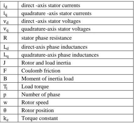
Where, Table 1 illustrates previous variable’s definition.
Table 1. Variable’s definition of PMSM model. id direct -axis stator currents
iq quadrature -axis stator currents vd direct -axis stator voltages
vq quadrature-axis stator voltages R stator phase resistance Ld direct-axis phase inductances
Lq quadrature-axis phase inductances J Rotor and load inertia
F Coulomb friction B Moment of inertia load Tl Load torque
p Number of phase w Rotor speed θ Rotor position ke Torque constant
From the speed state equation (3), it’s shown that if the d-axis current is maintained constant, the generated torque is proportional to the q-axis current. So, the q-axis current is the only control variable in the generated torque, which is similar to the torque control technique used in DC machines. The responsible for higher harmonics in fundamental and reluctance torque is non-ideal distribution of the stator winding or rotor magnet. The fundamental torque is the dominant torque production mechanism in most PMSMs but, the fundamental torque ripples appear at the high frequency range, i.e., multiple of six electrical shaft speed (6fe , where
feis the electrical shaft speed in Hz). Slot torque is the
circumferential component of attractive force that attempts to maintain the alignment between the stator teeth and the permanent magnets. Slot torque harmonics appear at frequencies that are multiple of Nsfe, where Ns is the number
of slots per pole pair [4]-[5].
The analytical modeling of the slot torque is challenging since it involves the complex field distributions around the slots of the stator. Thus, the slot torque is usually reduced in machine design procedure with the aid of numerical model [6]. Moreover, a large number of PMSMs are manufactured with anisotropic rotor. In this case the reluctance torque is negligible, and therefore it does not contribute to torque ripple. Motor with this construction produces only fundamental torque with large DC component and with higher harmonics [7]-[8]. It is assumed in the proposed work the availability of well designed PMSM with negligible reluctance and slot torque, which is often the case in high performance applications [9]. Thus our aim is to model fundamental torque only and concentrates on utilizing control feedback to minimize the ripple components. However, the slot torque may become a dominant ripple component in motors with different construction.
3.
SUGGESTED ALGORITHMS FOR
MINIMIZING TORQUE RIPPLES IN
PMSM:
3.1
Artificial Neural Network Algorithm
for Minimization of Torque Ripple in
PMSM Drives
PMSM dq-reference model can be described also, as:
did
dt = − R Ldid+ ω
Lq
Ldiq− ω
1
LdΦd θ +
1
Ld vd (5)
diq
dt = − R Lqiq− ω
Ld
Lqid− ω
1
LqΦq θ +
1
Lqvq (6)
Tm = p ∗ (idΦd θ + iqΦq θ ) (7)
dω dt =
Tm
J − B Jω −
1
JTl (8)
Where Tm is torque produced by the motor, J is the moment of
inertia, Φd θ is direct flux and, Φq θ is quadrature flux. A PMSM dq model equation (5)–(8) is similar to the standard model equations (1)–(4). The difference between the two models is that the back emf terms and motor torque expression depend on the position of the rotor, but the standard model does not. The permanent magnet flux linkages can be viewed as the sum of a fundamental component and the series of higher harmonics [4] following two equations (9)-(10) illustrate this:
Φd θ = Φd6sin 6θ + Φd12sin 12θ (9) Φq θ = Φq0Φq6cos 6θ + Φq12cos 12θ (10)
Where Φd6is six harmonic direct flux, Φd12is twelve harmonic direct flux, Φq0is zero harmonic quadrature flux, Φq6is six harmonic quadrature flux and, Φq12is twelve
harmonic quadrature flux. Where the coefficients Φdk Φqk,
based on back emf measurement and performed on PMSM is used in our simulations.
The model equations (5)–(8) are compressed into two equations for simplification, producing the next two equations (11)-(12): did dt diq dt = − R Ld 0
0 R
Lq
iid
q − ω
0 −Lq
Ld
Ld
Lq 0
iid
q − ω 1 LdΦd(θ)
1 LqΦq θ
+
1 Ldvd
1 Lqvq
(11)
Jdωdt = p ΦΦd(θ)
q θ T i
d
iq − Bω − Tl (12)
much slower mechanical dynamic. Then a speed loop controller is designed assuming electrical dynamic is infinitely fast.
3.1.1
Current Loop
Usually the current control subsystem consists of PI controllers of d-axis and q-axis currents. It is used to convert the torque reference value to current reference value.
A preparatory design step is to factor out the unknown parameters of the Φ(θ) function by the following:
Φ θ = ΦΦd θ , η∗
q θ , η∗ =
X θ . Φd6 Φd12 Φq0 Φq6 Φq12T (13)
Let η∗= Φd6 Φd12 Φq0 Φq6 Φq12T (14) Where X θ is a known 2*5 matrix whose entries are periodic functions of the rotor position, and η∗ is the unknown vector of the actual coefficients of Φ(θ) .
By using the vector η, to dynamically estimate η∗ it is desirable to set the id current to zero and to choose the iq
current to produce the desired torque reference T∗ [5], since from equation (7), Φd θ doesn’t have a DC component and
so, the nonzero id contributes only to torque ripples. Conversion of torque reference value T∗ to current reference value iq∗is realized using the extended current factor equation (15). The torque constant ke in equations (1)-(4) is replaced
by a term which contains harmonic functions ΦdkΦqkas in
equations (5)-(8). The current waveform is then shaped so that the produced fundamental torque is smooth and its ripple is suppressed.
id∗
iq∗ =
0
T∗
PΦq θ ,η
(15)
Since currents are closely related to torque production, next we specify a desired current vector that will produce the desired (ripple free) torque.
Voltage output of the controller is selected to satisfy equation (11) when desired values of currents are reached.
vd
vq =
Ld 0
0 Lq did∗
dt diq∗
dt
+ R 00 R iid ∗
q ∗ + ω
0 −Lq
Ld 0
id∗
iq∗ +
ω X θ η + 𝒫 id
∗
iq∗ −
id
iq (16)
Where design parameter 𝒫 > 0. One can Let η = η − η∗and i = i − i∗represent the deviations from the desired values.
Subtracting equation (16) from (11): Ld 0
0 Lq did
dt diq
dt
+ R 00 R + p iid
q
i d
i q +
ω L0 −Lq
d 0
i d
i q + ω X θ η = 0 (17)
An update law for η has to guarantee both η → 0 and i → 0.
By changes in the design parameter, 𝒫 we can control the parameter convergence rate. Where increasing it, will lead to rapid current convergence and a more aggressive control.
3.1.2
Speed Loop
A common way to achieve speed servo operation is to design a controller that produces the torque reference and its time derivative calculated from the difference between the actual and desired speed, which are fed to the Neural Network controller. The parameter of the speed loop controller is chosen to achieve the desired performance in speed tracking. The speed controller is based on a Neural Network Controller and the output of this neural is a reference torque and derivative of this torque T∗ can be calculated from the speed error (ω) using the same neural controller without integral action. The method is equivalent to generating T∗ , and T∗ using the same neural controller and an approximate derivative of the speed error [10]-[13]. Using the two controllers (speed and current) to produce the reference dq voltages. Then conversion to αβ voltages equations (18)-(19) as well as using SVPWM represents the novelty in our proposed approach.
vα= cos(θ) ∗ vd− sin θ ∗ vq (18) vβ = sin(θ) ∗ vd+ cos θ ∗ vq (19)
The αβ voltages then serve as inputs to (SVPWM) to produce the control signal to the inverter. Space vector modulation is based on the representation of the three phase quantities as vectors in a two-dimensional (αβ) plane. SVPWM can be implemented by the following steps: 1) Determining Voltage Space Vector 2) Determine time duration 3) Determining the switching time of each transistor (S1 to S6).
SVPWM technique has become a popular pulse width modulation technique for three phase voltage-source inverter in the control of AC motors. It is a more sophisticated technique for generating sine wave that provides a higher voltage to the motor with lower total harmonic distortion. The main aim this technique is to obtain variable output having a maximum fundamental component with minimum harmonics. It is used for the creation of alternating current (AC) waveforms; most commonly to drive three phase AC powered motors at varying speeds from DC using multiple class-D amplifiers. There are various variations of SVM that result in different quality and computational requirements. One active area of development is in the reduction of total harmonic distortion (THD) created by the rapid switching inherent to these algorithms. Space vector modulation is based on the representation of the three phase quantities as vectors in a two-dimensional (αβ) plane. The main target of introducing SVPWM is to minimize harmonic distortion in the current by selecting the appropriate switching vectors and determining their corresponding dwelling widths [14]-[15]. The αβ voltages serve as inputs to SVPWM to produce the control signals to inverter.
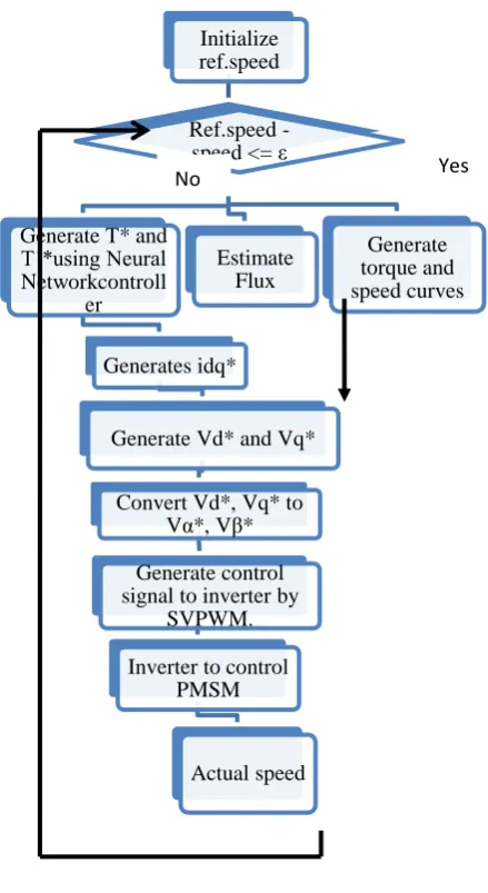
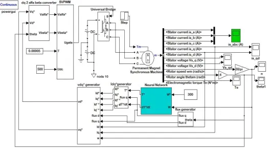
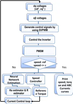
The flow chart of the first suggested control algorithm describing its steps is shown in Fig. 1. The Simulink block diagram of proposed torque ripple minimization using neural controller (first method) is show in Fig.2
The suggested neural controller algorithm (first method) is as follows:
Define the mathematical model of the system.
If difference between the speed and reference speed is less than or equal ε, stop and print torque and speed curves.
Else, generate the torque reference T∗ and T∗ from the speed error using neural controller.
Estimate flux (η) then, Calculate the reference dq current i∗and the derivative of this currents using equation (15).
Calculate the reference dq voltages (vq , vd) using vdq*
generator block as shown in fig.2.
Convert the reference dq voltages to αβ voltages by using equations (18) and (19).
Generate the control signal from αβ voltages using SVPWM which introduces its output signal to the inverter.
Fig.1. the flow chart of the adaptive suggested control algorithm.
For this suggested control algorithm:
The network has 3 layers with 2-4-2 structure: 2 input neurons, 4 hidden neurons and 2 output neurons.
The two inputs are the desired speed which equal 300 rpm and the actual speed which speed output from motor.
The two outputs are the reference torque and the derivative of this torque.
The learning rate is 0.01s.
The nonlinear threshold function is f(X) = (1- e−x)/ (1+e−x) is used in input and hidden neurons but, the linear threshold function is used in output neurons.
Initial neuron weights are zeros.
3.2
Neural Network Based Estimator For
Torque Constant And Stator Winding
Resistance
The axis stator inductance is modeled according to the q-axis current. The harmonics in the rotor flux linkage is considered and the torque constant estimation. A table of torque ripple compensating currents with respect to rotor position has been developed off-line and used in the controller [16]. This off-line combination of torque ripple minimization technique has a good balance between real- time calculation and operating performance. The effect of parameter variation on controller performance and torque ripple minimization is studied by simulation.
A PMSM parameter estimation strategy is introduced here with the use of a feed-forward neural network. The design of high-performance control system generally requires the use of adaptive control techniques when the parameters of the controlled process either are known or vary during normal operations. Among various alternative methods, the use of the technique known as model reference adaptive system seems to be one of the most feasible approaches for the implementation of adaptive control systems.
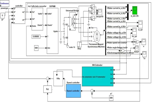
The prime characteristic of an adaptive system is the presence of a so-called reference model as part of the system, which can appear under various forms [2]-[10]. Fig.3, the proposed neural network estimator for stator resistance and torque constant (second method). The Simulink block diagram of proposed torque ripple minimization using neural controller (first method) is show in fig .4. The flow chart of the suggested control algorithm second method is show in Fig. 5. The suggested neural controller algorithm (second method) is as follows:
1-Model q-axis stator inductance and neglect the variation of d-axis inductance, since the d-axis current is controlled to be constant.
2-Adjust a model of the PMSM in parallel with the reference model, which is the motor itself.
3-Use the current error between reference and adjustable models as inputs to a feed-forward neural network adaptation algorithm to estimate the torque constant and the stator resistance.
4-Use also the current error to train the neural weights in the back propagation method.
5-Use the resistance R and the torque constant ke with speed controller to produce iq∗ .
6-Use iq∗to produce the reference dq-axis stator voltages
(vd∗, vq ∗).
7-Convert the vd∗and vq ∗ to αβ-stator voltages which are inputs to SVPWM.
8-The SVPWM technique is used to produce the switching control signals to be applied to the three-phase inverter circuit.
9-The control strategy of the SVPWM inverter is the voltage/frequency control method, which is based on the space-vector modulation technique.
Initialize ref.speed
Ref.speed -speed <= ε
Generate T* and T˙*using Neural Networkcontroll
er
Generates idq*
Generate Vd* and Vq*
Convert Vd*, Vq* to Vα*, Vβ*
Generate control signal to inverter by
SVPWM.
Inverter to control PMSM
Actual speed
Generate torque and speed curves Estimate
Flux
[image:4.595.57.277.216.618.2]A discrete PMSM model in the d-q reference frame is given below:
id(k + 1) = id(k) + TsL
d * (vd(k)+0.5 p*lq∗w (k) ∗ iq(k) -
R∗ id(k)) (20) iq(k + 1) = iq(k) + TsL
q * (vq(k)+0.5 p*ld∗w (k)∗ id(k) - 0.5
p*lq∗ ke∗w (k) – R∗ iq(k)) (21)
Where id(k + 1) and iq(k + 1) are the d-q axes stator
current, vd(k) and vq(k) are the d-q axes stator voltage and Ts is the sampling period.
The adjustable model is similar to the reference model with estimated resistance R and the torque constant k e replacing
the actual resistance R and torque constantke.
The error dynamics are of the form:
eiq(k + 1) = iq(k + 1) - i q(k + 1) = −TsL
q∗iq k R −
R − Ts ∗ 0.5pw(k)ke− k e
Lq (22)
eid(k + 1) = id(k + 1) - i d(k + 1) = -Ts ∗ id(k)R− R L
d (23)
If the d-axis current is controlled to be zero, the d-axis current error will not be sufficient to give the correct estimation. The current errors go to zero when all the parameters are correctly estimated.
[image:5.595.36.559.323.614.2]The problem was solved by injecting a constant magnetizing current. The undesirable effect of diagnostic injection is an additional copper loss leading to lower efficiency and lower torque per unit current than that in zero-d-axis-current operation. This trade-off between the torque ripple minimization and system efficiency can be easily compromised, since most of PMSM drives are high-efficiency systems.
Fig.3. The proposed neural network estimator for stator resistance and torque constant (second method)
[image:6.595.38.554.371.717.2]The outputs of the network are the changes of the estimated parameters.
The neural network weight adaptation is based on the least square method given by:
wij k + 1 = wij k − ƞƏwƏE
ij (24)
Where E is the index of the current errors wij is one of the
neural weights and ƞ is the learning rate.
Used Low pass filters for the current errors to avoid the effect of current noise. The filtered current errors and the changes of these filtered current errors are the inputs to the neural network.
The speed controller gives out torque command instead of q-axis current reference for the current controller. For the torque ripple, off-line identification is used to generate a table of compensating currents with respect to rotor position [16]. For the rotor-flux-linkage torque ripple, the torque constant is estimated in the current control loop. The current in the stator winding cannot follow the commands accurately if there is a considerable mismatch among the motor parameters in the current controller. Therefore, it is necessary to estimate the motor parameters. The fast response of the adaptation mechanism and the high bandwidth of the current loop enable the on-line estimation of the torque constant and the compensation of the flux linkage ripples. The torque ripple is proportional to the torque constant at that position [10], [17]. For this suggested control algorithm:
The network has 3 layers with 4-6-2 structure: 4 input neurons, 6 hidden neurons and 2 output neurons.
The four inputs are the dq-axis stator currents (id, iq ) and
the reference dq-axis stator voltages (vd∗, vq ∗).
The two outputs are resistance R and the torque constant ke.
The learning rate is 0.01s.
The nonlinear threshold function is f(X) = (1 - e−x) / (1 +e−x).
Initial neuron weights are zeros.
4.
PERFORMANCE EVALUATION
The simulation program is carried out in a numerical simulation, using one of Matlab’s toolboxes and Simulink (2009). All the system components are simulated using this program’s blocks.
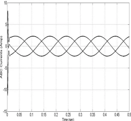
[image:7.595.304.559.76.438.2]The torque curve of the PMSM driven by a Neural Network controller first method is shown in Fig. 6, The speed curve of the PMSM driven by a Neural Network controller first method is shown in Fig. 7, The abc Currents curve of the PMSM driven by a Neural Network controller first method is shown in Fig. 8, The torque curve of the PMSM driven by a Neural Network controller second method is shown in Fig. 9, The speed curve of the PMSM driven by a Neural Network controller second method is shown in Fig. 10, The abc Currents curve of the PMSM driven by a Neural Network controller second method is shown in Fig. 11.
Fig. 5 The flow chart of the suggested control algorithm second method.
Fig.6 The torque curve of the PMSM driven by a Neural Network controller first method.
dq voltages (vd*, vq* )
αβ voltages
Generate control signals by using SVPWM
Control the Inverter
PMSM
speed -ref
speed <= ε
Neural Network Estimation
Ke estimator & R estimator
Current Control loop
Speed Controller
Referenc e Torque
Print speed, torq ue and ABC
Currents curves
[image:7.595.323.551.491.658.2]Fig.7 The speed curve of the PMSM driven by a Neural Network controller first method.
[image:8.595.324.530.324.520.2]Fig.8 The abc Currents curve of the PMSM driven by a Neural Network controller first method.
Fig.9 The torque curve of the PMSM driven by Neural Network controller second method.
Fig.10 The speed curve of the PMSM driven by Neural Network controller second method.
[image:8.595.59.277.355.556.2] [image:8.595.323.547.568.720.2]5.
SIMULATION RESULTS ANALYSIS
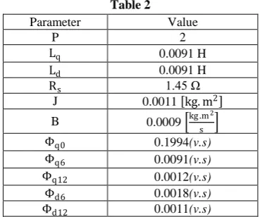
After the theoretical derivation, the proposed controllers were suggested and tested in simulations. An ideal scenario is simulated with results confirming the correctness of the design. All simulations were performed using the Matlab Simulink toolbox 2009. Table 2, Contains of the parameter values for PMSM that will be used in the present work.Table 2
Parameter Value
P 2
Lq 0.0091 H
Ld 0.0091 H
Rs 1.45 Ω
J 0.0011 kg. m2
B 0.0009 kg .m
2
s
Φq0 0.1994(v.s)
Φq6 0.0091(v.s)
Φq12 0.0012(v.s)
Φd6 0.0018(v.s)
Φd12 0.0011(v.s)
The performance criterion used in this work to evaluate the effectiveness of the proposed scheme for torque ripple minimization is the torque ripple factor (TRF). TRF is defined as the ratio of the peak-to-peak torque ripple to the rated torque of the PMSM is given in equation (25).
TRF = Tm ,pk −pk
Tm ,rated ∗ 100 % (25)
Where, Tm,pk −pk is the peak-to-peak torque ripple and
Tm,rated is the rated torque.
[image:9.595.74.259.156.310.2]Dynamic characteristic values. For the proposed neural controller (first method), in torque curve fig 6, the overshoot percentage is 405%, the delay time is 3.043E-4s, the Peak time is 1.9535E-3s, the rise time is 2.545E-4s, and the torque ripple percentage is 1.26%. In speed curve fig 7, there is no overshoot, the delay time is 2.39E-3s, there is no Peak time, and the rise time is 3.186E-3s. For the proposed neural controller (second method), in torque curve fig 9, there is no overshoot, the delay time is 9.46E-4s, the Peak time is 4.72E-3s the rise time is 1.851E-4.72E-3s, there is no steady state error, and the torque ripple percentage is 0.46%. In speed curve fig 10, there is no overshoot, the delay time is 2.8E-3s, there is no Peak time, and the rise time is 4.193E-3s. Table 3 shows all previous results.
Table 3. Comparative Analysis between dynamic characteristics of a two suggested methods of neural
network control.
First method Second method
Torque
Maximum overshoot
(Mp)
7.874 n.m 1.5419 N.m
delay time (td) 3.043E-4 s 9.46e-4 s peak time (tp) 1.9535E-3 s 4.72E-3 s rise time (tr) 2.545E-4 s 1.851E-3 s
steady state 1.55 n.m at 0.016s
1.55 n.m at 9.4e-3 s Ripple
(max-min) 0.0196 0.0072
speed
Maximum overshoot
(Mp)
no overshoot no overshoot
delay time (td) 2.39E-3 s 2.8E-3 s
peak time (tp) no No
rise time (tr) 3.186E-3 s 4.193E-3 s steady state 300 rpm at
0.31 s
300 rpm at 8.4E-3 s
It’s observed that the proposed two methods of neural controller succeeded to enhance the ripples. This reduction was around 1.26% with the value of ripples equal 0.0196 N.M for the neural network, 0.46% with the value of ripples equal 0.0072 N.M for neural network based estimator for torque constant and stator winding resistance. Moreover, this result is compared to other publication for more validation. V. Petrovic et al [4], Torque ripple percentage was ≈ 4% which is still higher than a proposed two methods of neural network. While W. Qian and Panda [18], Torque ripple percentage was 3.9% which is still higher than a proposed two methods of neural network. P. Mattavelli et al. [19], Torque ripple percentage was ≈ 3.8% which is still higher than the proposed two methods of neural network. H.M. Hasanien et al. [13]. Their result was 12%. Torque ripples in compression to our two methods of neural network are actually higher. M.Tarnik et al. [20], Torque ripple percentage was ≈ 4% which is also higher than the proposed two methods of neural network. Table 4, presents the torque ripples than percentage, which have been calculated from different works. The table shows that the proposed control reduced the percentage torque ripples to a good value rather the previous work [14]-[15]. We can further reach to optimize the output for torque and reduce the amount of percentage error by combining two neural networks first method, and second method.
Table 4: The percentage torque error obtained in various control strategies in different works.
Control Strategies Torque Ripple Percentage (TRF) Proposed Neural network controller (first
method). 1.26%
Proposed neural network based estimator for torque constant and stator winding resistance (second method).
0.46%
(V. Petrovic et al, 2000) [4]. ≈ 4%
(Qian and Panda, 2004) [18]. 3.9%
(P. Mattavelli, 2005) [19]. ≈ 3.8%
(H. Hasanien, 2010) [13]. 12%
(M.Tarnik and J.Murgas, 2011) [20]. ≈ 4%
6.
CONCLUSION
[image:9.595.302.569.458.620.2]7.
ACKNOWLEDGMENT
We are very grateful to the editor and reviewers for their valuable comments and suggestions to help improving this work.
8.
REFERENCES
[1] T.M. Jahns andW. L. Soong, ―Pulsating torque minimization techniques for permanent magnet AC motor drives—A review,‖ IEEE Trans. Ind. Electron., vol. 43, pp. 321–330, Apr. 1996.
[2] T.liu, I.Hussain, M.Elbuluk, ―torque ripple minimization with on-line parameter Estimation using Nural network in Permanent magnet Sysnchronous Motors‖ IEEE 1998.
[3] T.M. Jahns and W. L. Soong, ―Pulsating torque minimization techniques for permanent magnet AC motor drives—A review,‖ IEEE Trans. Ind. Electron., vol. 43, Apr. 1996.
[4] V.Petrovic and R.Ortega,‖Design and Implementation of an Adaptive Controller for Torque Ripple Minimization in PM Synchronous Motors‖ "IEEE Transactions on Power Electronics, VOL. 15, NO. 5, 2000.
[5] H. Khalil, Nonlinear Systems, 2nd ed. Englewood Cliffs, NJ: Prentice Hall, 1996.
[6] Zhang Jianzhong, Cheng Ming, Chen Zhe. ―Optimal design of stator interior permanent magnet machine with minimized slot torque for wind power application‖, Energy Convers Manage 2008.
[7] A. Kaddouri and H. Le-Huy, ―Analysis and design of a slotlessNdFeB permanent magnet synchronous motors for direct drive,‖ in Proc. Rec. IEEE IAS Annu. Meeting, 1992.
[8] C. Studer,A.Keyhani, T. Sebastian, and S. K.Murthy, ―Study of slot torque in permanent magnet machines,‖ in Proc. Rec. IEEE IAS Annu. Meeting, New Orleans, LA, October 1997.
[9] D. C. Hanselman, ―Minimumtorque ripple, maximum efficiency excitation of brushless permanent magnet motors,‖ IEEE Trans. Ind. Electron., vol. 41, June 1994.
[10] C. Elmas and O. Ustun ―A hybrid controller for the speed control of a permanent magnet synchronous motor drive‖Control Engineering Practice 16 (2008).
[11] R. Ortega, A. Loria, P. J. Nicklasson, and H. Sira-Ramirez, Passivity Based Control of Euler–Lagrange Systems. London, U.K.: Springer Verlag, 1998.
[12] Fernández P, Güemes JA and Iraolagoitia AM. ―Speed control of permanent magnet synchronous motors by current vector control‖. In: International conference on electrical machines (ICEM); September 2006.
[13] H. Hasanien, ―Torque ripple minimization of permanent magnet synchronous motor using digital observer controller‖ Elsevier, 2010.
[14] [14] k. V. kumar, P. A.l Michael, J. P. John and S. Suresh Kumar, ―simulation and comparison of spwm and svpwm control for three phase inverter‖, arpn journal of engineering and applied sciences, vol. 5, no. 7, july 2010. [15] A. Iqbal and S. M. Ahmed, M.A.Khan, H.Abu-Rub ―Generalised simulation and experimental implementation of space vector PWM technique of a three-phase voltage source inverter‖, ijest Vol. 2, No. 1, pp. 1-12, 2010.
[16] H. Joachim, S. Lother, ―identification and compemsation of torque ripple in high precision permanent magnet motor drives‖, IEEE TRAN IE, vol.43, No.2, 1996, pp.309-330.
[17] H. Rasmussen, P. Vadstrup, and H. Borsting, "Adaptive sensorless field oriented control of PM motors including zero speed," in IEEE.Industrial Electronics, May 2004. [18] W. Qian and S. K. Panda,‖Torque Ripple Minimization
in PM Synchronous Motors Using Iterative Learning Control‖ IEEE Trans, VOL. 19, NO. 2, MARCH 2004 [19] P. Mattavelli, L.Tubiana, and M. Zigliotto,