Design and Analysis of Digital PWM Controller for
DC-DC Power Converter
D.Vinodini, V.Vasanprabhu, V.Rajini,
PG Student, AIHT, chennai. Asst.prof, AIHT, chennai Prof, SSNCE, chennai.ABSTRACT
The aim of the project is to propose a simple digital current mode control technique for dc-dc converters. In the proposed current mode control method, the inductor current is sampled only once in a switching period. A Compensating ramp is used in the modulator to determine the switching instant ana-lytically from the steady state condition .The trajectory of inductor current during the switching period is not estimated in this method. It effectively increases the maximum switch-ing period of the converter when a particular controller is used to implement the control algorithm. It is showed that proposed digital method is versatile enough to implement the control algorithm any one average, peak and valley current mode by adjustment of the sampling instant of the inductor with respect to turn –on instant of the switch. The proposed digital current mode control algorithm is tested on a 12-V input and 1.5-V,7A output buck converter is switched at 100 KHZ and ex-perimental results are presented.
Index terms
- current mode control, dc-dc converters, digi-tal control, digidigi-tal current mode control, steady state stability, voltage-mode control, voltage regulator(VR), voltage regula-tor module(VRM).1. INTRODUCTION
Recently digital power supplies have become more and more popular in the field of power electronics. power supplies with a digital controller can overcome many drawbacks of those with an analog controller, and provide more functions that can improve the system performance, such as noise immunity, programmability, and communication capability. Current-mode control has been widely used in the power converter design for several decades .There are many different ways to implement the current mode control. Due to unique character-istics, current-mode control architectures with different im-plementation approaches have been used in power converter design to achieve current sharing, AVP control, light-load efficiency improvement.In this paper the primary objective to investigate a new general modeling approach for current mode control with different implementation methods. Implementa-tion of advanced control techniques gives best results in digi-tal current mode control .A digidigi-tal application of current mode control is introduced. Usually Digital control employ voltage mode control principle[1]-[5][9] for VRM application. How-ever current mode control may be preferred because VRM requires Adaptive voltage positioning (AVP)[10]. High reso-lution digital pulse-width modulator (DPWM) is considered to be indispensable for minimizing the possibility of unpredicted limit –cycle oscillations, but results in high cost, especially in the application of voltage.
Digital controller results may only be possible to sample the fast changing inductor current only once in the switching
period [9].It would require a very fast ADC and complex digital signal processing hardware. The digital current con-trol[6] samples the current only once in the switching period based on the predictive control principle in according to con-trollaw, such as inductance and the input and output voltages. This paper follows the current mode control principle is used for this technique[8] . This paper describes the design and implementation of digitally controlled buck dc-dc converter in a pulsewidth modulation level. By sampling the inductor current according to the switching period, the duty ratio is determined by solving in which the sampled current becomes equal to the periodic waveform in the modulator by adding the compensating ramp to the output of the voltage error amplifier to analyse the steady- state stability condition. In this method we are describing the three structures of digital pulse width modulator (DPWM) implement peak, average and valley cur-rent-mode controls. Simulation results of a 1.5, 7A buck con-verter[7] switched to validate the proposed model of digital current mode control and the stability condition.
2. DIGITAL CONTROLLER
The block diagram of a dc-dc converter that uses analog cur-rent –mode control scheme is shown in Fig.1.In this diagram the output of the voltage error amplifier is converted to cur-rent reference iref by the modulator. The modulator of the current mode controller consists of a clock generator, an S-R F\F, and a comparator. There is a problem in operating princi-ple of the steady state stability for duty ratio greater than 0.5 .The use of the compensating ramp signal to ensure stability for duty ratio greater than 0.5 is the solution to the problem. A digital approach to current-mode control overcomes many limitations of the digital voltage mode PWM controllers. . Current mode control also uses the error voltage to control the maximum inductor current, which turns the inductor current, involtage controlled source.Also,current mode control is chal-lenging voltage mode techniques for switch mode power sup-plies digital design applications. Digital current mode control brings the steady state condition in the operating condition.
. Digital signal processors(DSCs) can perform digital cur-rent mode control with the proper analog-digital convert-ers(ADC) able to measure inductor current at appropriate points during PWM cycle. Combining digital control with current mode topologies can bring higher performance than combinations of analog or voltage mode approaches. Howev-er, the design of a low-cost and high performance digital con-troller is still a challenge.
The block diagram of a digital current mode control of dc-dc converter is shown in Fig .2.In this paper digital controller samples the sensed current only once in the every switching period[9]. Therefore actual trajectory of the inductor current within the switching period is not known to the controller. This implies that in digital implementation is a comparison of the sampled current and current reference will produce the duty ratio either 1 or 0. This method proposes [6] the convert-er topology, the inductance and the input and output voltages
to estimate slope of
the current within a switching period and there by can produce the duty ratio between 1or 0. This paper based on the current mode law to determine the duty ratio, if we add a periodic compensating ramp ic(t)=-mc.t,<=t<=TS to the current reference Iref in order to generate the modulator cur-rent expression. iM(t) =iref +ic(t) and then by finding out the
instant (dTS) at which the sampled current iLS becomes equal to iM(t).
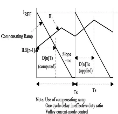
The circuit operation can be divided into three modes. Three modes are peak current mode, valley current mode and aver-age current mode.. Whenever the current mode converter is valley and average is secondary to the operation of the current loop. As long as the dc current is sampled, current mode oper-ation is maintained.The current sampling in this method is treated as valley current of the inductor current, therefore the beginning of the control period and the turn-on instant of the switch are synchronized in Fig.3.
The circuit operation can be divided into three modes. Three modes are peak current mode, valley current mode and aver-age current mode.Whenever the current mode converter is valley and average is secondary to the operation of the current loop. As long as the dc current is sampled, current mode oper-ation is maintained
[image:2.595.319.547.184.403.2]Note: The current is sampled only once in a switching period
Fig.2.Block diagram of the digital current –mode control of dc-dc converter
The current sampling in this method is treated as valley current of the inductor current, therefore the beginning of the control period and the turn-on instant of the switch are syn-chronized in Fig.3a.we start every control period with the off-time of the switch then peak current mode can be
implement-ed .It is also possible to implement average current mode control with appropriate choice of the sampling instant as shown in .In this case on duration of the switch is placed symmetrically around the center of the switching period. The peak current mode and valley current mode have some little variations.Therefore, under steady state sampled current will be equal to the average current of the inductor. The inductor current changes its slope due to turn-on or turn off of the switch taken at valley or at the peak mode
[image:2.595.55.293.542.658.2].
Fig. 3. Proposed digital current mode control method forimple mentation of valley current –mode control.
3. DIGITAL PULSE WIDTH
MODULA-TOR (DPWM)
The function of the digital pulse width modulator is to pro-duce in the digital mode the switching signals are correspond to the calculated duty ratio. High resolution digital pulse – width modulator is considered to be indispensable for mini-mizing the possibility of the unpredicted limit-cycle oscilla-tions.In this paper firstly introduces several DPWM modula-tion methods to improve the DPWM resolumodula-tion. The differ-ence between the analog structure and digital structure is that two major quantizers the analog to digital converter(ADC) and digital pulse width modulator(DPWM), are added in the system.
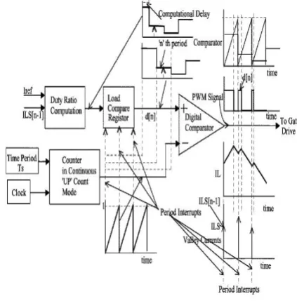
DPWM with high resolution is expensive and introduces more challenges to the digital controller design, especially in the application of voltage regulator(VR) for microprocessors. In the counter-based DPWM, a counter is used to count the system clock cycle to determine the on-time and switching cycle, duty cycle resolution is determined. However, in cur-rent-mode control the sensed inductor-current ramp, which is sensed to produce DPWM. In proposed implementation is essentially consist of a counter and a digital comparator as shown in Fig.4.
reso-lution is given by the ratio FS /Fclk. The output of the coun-ter is connected to one of the inputs of the comparator. The other input of the comparator is connected to a compare – register that holds the value of duty ratio which has already been computed. The loading of the compare-register is done in synchronism with period interrupt. The counter in any one of it’s counting mode(such as continuous–up or continuous up-down)produces period interrupt corresponding to the switching period of the converter.
In the connection configuration shown in Fig.4the counter is in continuous-up counting mode with a period value corre-sponding TS. .The non-inverting of the comparator is con-nected to the output of the compare register and the inverting terminal is connected to the output of the counter .The result-ant switching pulses and the corresponding current waveforms are also shown in Fig.4.It may be noted that this configuration of DPWM implements valley current-mode control. It can generate PWM according to some period variations shown in valley current mode control denoted same in the peak current mode by the inverting operation and also given in the average current mode control techniques.
[image:3.595.318.548.384.670.2]However the structure of DPWM is versatile enough to im-plement [4] average and peak current-mode control as well. For peak current-mode control, a value corresponding to (1-d[n] )TS is loaded into the register. The compare-register in this case connected to the inverting terminal of the digital comparator. The output of the counter, that operates in the continuous-up counting mode, is connected to the non-inverting terminal. The resultant switching pulses and the corresponding current waveforms for peak current-mode con-trol are shown.
Fig .4.DPWM structure to implement valley current mode control
For average current mode control, the counter is operated in continuous-up-down counting mode with the counter loaded with a value corresponding to TS/ 2. An integer corresponding to (1-d[n])/ 2TS is loaded to the compare-register and it is connected to the inverting terminal of the digital comparator. It may be noted that though the currents are sampled at the beginning of the control cycle, in all the three cases of cur-rent-mode control, still three different types of curcur-rent-mode
control are implemented by changing the configuration of the DPWM. Inthe proposed digital current-mode control scheme the compensating ramp is a part of the basic structure, as it is required irrespective of the duty ratio of the converter and its slope of the ramp needs to achieve steady-state stability of the inductor current.
4. MATLAB SIMULATION
The conventional analog current mode shown in fig.5.and the proposed digital average current mode control technique is
shown in Fig.6. is tested on a
Vg =12-V input buck converter switched at 100khz that pro-duces the nominal output of 1.5V,7A. The inductance of the buck converter is L =27µH and the capacitance is C=100µF.Proportion Integral controller is used in the error amplifier having proportional gain value is 1.4087 and Integral gain value is 1.2296.The inductor current
is sensed with an
effective resistance of 0.22Ω ,therefore inductor current sam-pled in 100000 samplings at once in switching period. In the average current mode control it samples at the time value at average value of half of the sampling period. And the same input and output is shown in Fig 6.peak current mode control and valley current mode control is shown in Fig.7. This model uses the transfer function samples at the 100000 samples at the single instant. The steady state stability condition is shown
from this cases by use of
compensating ramp to maintain the duty ratio greater than 0.5.
Fig.5.simulation of analog current mode control
[image:3.595.74.286.423.638.2]Fig.7.Simulation of digital peak current mode control
Fig.8.Simulation of digital valley current mode control
5. SIMULATION RESULTS
5.1 Analog current mode control :
(a)
(b)
Fig.9.shows the analog current mode .(a) represents the inductor current=7A,(b) represents the PWM signal.
5.2 DIGITAL CURRENT MODE
CONTROL
5.2.1Digital average current mode control
:
(a)
(c)
(d)
Fig.10.shows the digital average current mode.(a) repre-sents the output voltage=1.5V,(b) reprerepre-sents the inductor
current=7A, (c) represents the error signal and compen-sating ramp signal,(d) represents the PWMsignal.
5.2.2 Digital peak current mode control:
(a)
(b)
Fig.11.shows the digital peak current mode control.(a)represents the error signal andcompensatingrampsignal,(b)represents the PWM
signal
5.2.3 Digital valley current mode control
:
(a)
(b)
Fig.12.shows the digital valley current mode control.(a) represents the error signal and
com-pensating ramp signal,(b) represents the PWM signal
The simulation results are given in the above fig-ures.Fig.9.shows the analog current modeControl and the proposed digital average current mode control shown in Fig.10. and proposed digital peak current mode control shown in Fig.11.and proposed digital valley current mode control shows in Fig.12.This results are showsthat can able to gener-ate PWM signal in thevarious current mode control tech-niques.
6. CONCLUSION
equating the sampled current to the equation of the modulator current that is obtained by adding the compensating ramp to the output of the voltage error amplifier .This paper analyses the steady state condition by use of compensating ramp. The advantage of the proposed digital method is the simplicity in the circuit and improved the system response and the compu-tational burden is the digital controller is reduced and it cost is low and higher performance. The configuration of the DPWM for implementations of all the three variations of cur less in the proposed digital current-mode controls, have been proved. Simulation results of a 1.5-V,7-A buck converter switched at 100khz proved the validity of proposed digital current mode control and also shows the stability condition. As a result proposed digital current control method is simple and is easily implemented and its also going to implemented in the digital hardware in future cases.
7. REFERENCES
[1] M. Wu, J. Xiao, D. Markovic, and S. R. Sanders, “Digital PWM control: Application in voltage regulator mod-ules,” in Proc. IEEEPESC’99 Conf., 1999, pp. 77–83
[2] A. P. Dancy and A. P. Chandrakasan, “Ultra low power control circuits for PWM regulators,” in Proc. IEEE PESC’97 Conf., 1997, pp. 21–27.
[3] A. P. Dancy, R. Amirtharajah, and A. P. Chandrakasan, “High-efficiency multiple-output dc–dc conversion for low voltage systems,” IEEE Trans. VLSI Syst., vol. 8, no. 3, pp. 252–263, Jun. 2000.
[4] A. V. Peterchev, J. Xiao, and S. R. Sanders, “Architec-ture and IC implementation of a digital VRM controller,”
IEEE Trans. Power Electron., vol. 18, no. 1, pt. 2, pp. 356–364, Jan. 2003.
[5] B. J. Patella, A. Prodic, A. Zirger, and D. Maksimovic, “High-frequency digital PWM controller IC for dc–dc converter,” IEEE Trans.Power Electron., vol. 18, no. 1, pt. 2, pp. 438–446, Jan. 2003.
[6] J. Chen, A. Prodic, R. W. Erickson, and D. Maksimovic, “Predictive digital current programmed control,” IEEE Trans. Power Electron., vol.18, no. 1, pp. 411–419, Jan. 2003.
[7] S. Saggini, M. Ghioni, and A. Geraci, “An innovative digital control architecture for low-voltage, high-current dc–dc converters with tight voltage regulation,” IEEE Trans. Power Electron., vol. 19, no. 1, pp.210–218, Jan. 2004
[8] S. S. Hsu, A. Brown, L. Rensink, and R. D. Middlebrook, “Modeling and analysis of switching dc-to-dc converters in constant-frequency current programmed mode,” in Proc. IEEE PESC’79 Conf., 1979, pp.284– 301.
[9] SouvikChattopadhyay and Somshubhra Das, “A Digital Current-Mode Control Techniquefor DC–DC Convert-ers”, IEEE TRANSACTIONS ON POWER ELECTRON-ICS, VOL. 21, NO. 6, NOVEMBER 2006.
[10] Y. Ren, K. Yao, M. Xu, and F. C. Lee, “Analysis of the power delivery path from 12-V VR to the microproces-sor,” IEEE Trans. Power Electron.,vol. 19, no. 6, pp. 1507–1514, Nov. 2004.