© 2017, IRJET | Impact Factor value: 5.181 | ISO 9001:2008 Certified Journal | Page 421
SMART HUMAN TWO WHEELER SAFETY SYSTEM
Mr.K.ELAIYARAJA
1, K.RAJ KUMAR
2, M.SHEIK MOHAMED
31
Assistant professor, Department of information Technology, Valliammai Engineering College, Tamilnadu , India
2Department of information Technology, Valliammai Engineering College, Tamilnadu , India
3
Department of information Technology, Valliammai Engineering College, Tamilnadu , India
---***---Abstract -
Set, check and Go to have safe and happy drive.In this project, we proposed that bike system to check whether the rider wears the helmet or not then after only it will start to go else it won’t start. This project is developed under the safety precaution for the people to value human being’s life. The helmet has in built sensor like alcohol sensor, touch sensor, IR sensor and etc. These are used to send the information that all are ok and the start signal is transmitted to receiver which is located at bike. After receiving the start signal then only the bike starts else it will wait for the signal. The RF transmitter and receiver is used here to communicate between helmet and bike. Our system will set everything first then check the requirement to start the bike. A vibration sensor is placed in bike which is detects the accident to make an alert to rider.
Key Words: Helmet, Accelerometer Sensor, Alcohol
Sensor, Push button, Vibration Sensor, IR Sensor, Microcontroller.
1. INTRODUCTION
Every year in India a many number of deaths occur due to road accidents. Drivers on two-wheeler contribute significantly to these numbers. In a large number of two wheeler accidents, deaths occur because no preventive actions have been taken by the driver or those sitting in the two-wheeler. As greater risk is involved in riding a two wheeler therefore, it becomes compulsory to use protective guard while riding two-wheeler. In our paper we propose one such security systems that make it mandatory for the user to wear a helmet before riding a two wheeler. This system reduces the death during an accident. We also take into consideration a prototype that has been developed for motor cycle riders. Now a day there has been increased the total number of deaths that occur due to road accidents in the last 10 years. Fast driving, ignoring the traffic rules and absence of wearing shield have been some of the most important reasons for these deaths. The driver must have a some defense in case any accident occurs. A survey performed in India confirmed that there were a total of 1, 34, 513 deaths due to road accidents in India in the year 2015. The number increased to 1, 42, and 485 in the year 2011.So we reduced the total number of accidents in India and save many human’s life. . In our paper we propose one such security systems that make it mandatory for the user to wear
a helmet before riding a two wheeler. People will be obedient to follow the driving rules.
2. SYSTEM DESCRIPTION
2.1 Helmet
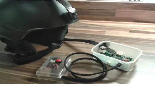
The helmet was a normal driving helmet that had been instilled with two push buttons to sense if the driver wear a helmet or not. When the driver doesn't wear the helmet correctly the vehicle won't start .In that helmet build with the alcohol sensor and IR sensor, when the alcohol sensor detect the alcohol smell when the driver drunk the alcohol or not. If the driver drunk the alcohol the sensor will identify the smell and stop the vehicle or else it won't start the vehicle. When the IR sensor will identify the driver wear the helmet lock properly or not. If the driver didn't wear the helmet lock properly the bike will not start. The helmet was not a normal driving helmet that had been instilled with 2 sensors and one push button that were connected an micro controller board in fig1. This development board also had a wireless receiver/transmitter attached to it helmet. The Atmega16 was the brain of this section of the setup and was concerned with the transmission of messages to the receiver part as soon as the helmet is worn by a human being. A MAX-233 IC is used for conversion of data to RS-235 protocol.
Fig -1: Helmet connected with sensor
[image:1.595.309.561.528.668.2]© 2017, IRJET | Impact Factor value: 5.181 | ISO 9001:2008 Certified Journal | Page 422
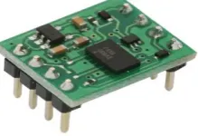
2.2 Alcohol Sensor
An alcohol sensor detects the smell of alcohol gas in the air and an analog voltage is an output reading with the input voltage. The sensor can activate at temperatures ranging from -10 to 50° C with a power supply is less than 150 Ma to 5V and gives signal to micro controller. The sensing range is from 0.04 mg/L to 4 mg/L, which is suitable for breathalyzers with analysis into them.
Fig -2: Alcohol sensor
The MQ-135 Alcohol sensor senses the gases like ammonia nitrogen, oxygen, alcohols, aromatic compounds, sulfide and smoke with the alcohol sensors. The boost converter of the chip MQ-3 alcohol sensor is PT1301. The operating voltage of this gas sensor is from 2.5V to 5.0V. The MQ-3 gas sensor has a lower conductivity to clean the air as a alcohol sensing material. In the atmosphere we can find polluting gases, but the conductivity of alcohol sensor increases as the concentration of polluting gas increases. MQ-135 alcohol sensor can be implementation to detect the harmful purpose. It has potential to detect different harmful gases. The MQ-135 alcohol sensor is low cost to purchase. The basic image of the MQ-135 alcohol sensor is shown in the above figure. This alcohol sensor is suitable for detecting the alcohol concentration on your breath, just like your common breathalyzer. It has a high sensitivity and fast response time. Sensor provides an output based on alcohol concentration. The drive is very simple; all it needs is one resistor. A simple interface could be a 0-3.3V ADC. The alcohol sensor is easy to identify the alcohol smell and send the signal to the microcontroller. When the driver drunk the alcohol they will not start and didn’t send the signal to the microcontroller.
2.3 IR Sensor
An Infrared (IR) sensor is used to detect the skin in front of the helmet or to differentiate between the configurations of the sensor. The picture shown is a very simple black box model of the IR Sensor. The sensor emits will identity the user wear the helmet lock properly gives a signal when it detects the sensor. An IR sensor consists of an emitter, detector and associated circuitry with the helmet. The circuit required to make an IR sensor consists of two parts; the transmitter circuit and the receiver circuit.The transmitter is simply a capture a signal and the detector is simply an IR photo diode which is sensitive to IR sensor of the same wavelength as that transmitted by the IR LED.
Fig -3: IR sensor
An infrared sensor is an electronic instrument device which is used to sense the certain characteristics of its surroundings by either emitting and/or detecting infrared radiation with the transmitter and receiver. Infrared sensors are also capable of measuring the heat being emitted by an object and detecting motion. All objects with a temperature above absolute zero emit heat energy in the form of radiation and the signal to the microcontroller. They work entirely by detecting the energy given off by other objects with the system.
2.4 Push Button
[image:2.595.323.505.100.207.2]The helmet is inserted into two push buttons. If the driver wear the helmet and touch the push button inside the helmet then only the push button signal send to the microcontroller.
Fig -4: Push button
Transmitter receives the signal from the microcontroller and gives the input into digital form. When this push button is helps to identify the driver for wearing helmet. This is mainly used for save the many people’s life in our country. Crystal oscillator is send the input the microcontroller and output comes into the digital form with USART communication.
2.5 Microcontroller
[image:2.595.51.178.204.315.2] [image:2.595.319.437.442.521.2]© 2017, IRJET | Impact Factor value: 5.181 | ISO 9001:2008 Certified Journal | Page 423 the system. The PIC microcontrollers often appear under the
[image:3.595.55.200.149.267.2]brand name under microcontroller function.
Fig -5: Microcontroller
Every PIC microcontroller has a set of system that also functions as RAM (random access memory) that easy to access the memory. Special purpose control registers for on-chip hardware resources are also mapped into the data space into the subsystem. All these two sensors and push buttons that would be connect with the microcontroller and finally send the send the signal to the transmitter. When these three sensors will activate then the microcontroller would process the signal and send to the transmitter.
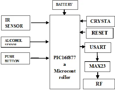
[image:3.595.309.568.155.299.2]2.6 Architecture Diagram for Helmet
Fig -6: Architecture diagram for helmet
The helmet was a normal driving helmet that had been instilled with two push buttons to sense if the driver wear a helmet or not. In this project we have developed a secure helmet system with IR sensor, Alcohol sensor, Vibration sensor. IR sensor is used to detect whether the driver wears the helmet or not. Alcohol sensor is used to detect whether the driver has consumed alcohol or not. Vibration sensor is used to detect accident automatically. Finally the input from the sensors is obtained by PIC microcontroller and
transmitted using RF module. Depending on the input the vehicle is ignited. Each Transmitter carries its own frequency. The Radio Frequency Receiver receives the Zone Code transmitted by the Transmitter.
Fig -7: Sensors connected with microcontroller
We have developed a secure helmet system with IR sensor, Alcohol sensor, and Vibration sensor. IR sensor is used to detect whether the driver wears the helmet or not. Alcohol sensor is used to detect whether the driver has consumed alcohol or not. Vibration sensor is used to detect accident automatically. Finally the inputs from the sensors are obtained by PIC microcontroller and transmitted using RF module. Depending on the input the vehicle is ignited. Each Transmitter carries its own frequency. The Radio Frequency Receiver receives the Zone Code from the transmitted and send signal to receiver. According to the frequency of transmitter the input is low. The output is fed to Buffer. This unit provides unit gain amplification to the received Zone Code signal and drives the relay for further feeding. The helmet has in built sensor like alcohol sensor, touch sensor, IR sensor and etc. These are used to send the information that all are ok and the start signal is transmitted to receiver which is located at bike. After receiving the start signal then only the bike starts else it will wait for the signal. The RF transmitter and receiver is used here to communicate between helmet and bike. Our system will set everything first then check the requirement to start the bike. A vibration sensor is placed in bike which is detects the accident to make an alert to rider.
2.7 Architecture Diagram for Bike
[image:3.595.62.253.462.612.2]© 2017, IRJET | Impact Factor value: 5.181 | ISO 9001:2008 Certified Journal | Page 424
Fig -8: Architecture diagram for bike
2.8 RF Transmitter/Receiver
The RF module, as the name considers the operation at Radio Frequency Signal. The corresponding frequency range varies from between 30 kHz & 300 GHz. In this RF system, the digital data is represented as variation in the amplitude of carrier wave the data has been transmitted. This kind of modulation is known as Amplitude Shift Keying (ASK).
[image:4.595.341.451.241.316.2]
Fig -9: RF Transmitter/Receiver
Transmission through the RF is better than IR because of many reasons to transfer the signal. Firstly, signals through RF can travel along with the transmitter and receiver. Also, while IR mostly operates in line-of-sight mode, RF signals can travel even there is an obstruction between transmitter & receiver. Next, RF transmission is more strong and reliable than IR transmission. RF communication uses a specific frequency unlike IR signals which are affected by other IR emitting sources.
2.9 Vibration Sensor
[image:4.595.99.206.407.619.2]Vibration sensor is used to detect accident automatically. Finally the inputs from the sensors are obtained by PIC microcontroller and transmitted using RF module. Depending on the input the vehicle is ignited. Each Transmitter carries its own frequency. The Radio Frequency Receiver receives the Zone Code from the transmitted and send signal to receiver. According to the frequency of transmitter the input is low.
Fig -10: Vibration sensor
The output is fed to Buffer. This unit provides unit gain amplification to the received Zone Code signal and drives the relay for further feeding. The helmet has in built sensor like alcohol sensor, touch sensor, IR sensor and etc. These are used to send the information that all are ok and the start signal is transmitted to receiver which is located at bike. After receiving the start signal then only the bike starts else it will wait for the signal. The RF transmitter and receiver are used here to communicate between helmet and bike.
Fig -11: Vibration sensor and Accelerometer sensor with microcontroller.
CONCLUSION
At the end of the project, the system should makes it mandatory for the user to wear a helmet before riding a two wheeler , if any accident occurs the sensors will detect the accident and send the alert messages to family members. By seeing those many benefits for this project and save the
RF RX RECECIVES THE SIGNAL FROM
THE RF TX
BIKE ARE READY TO START
SAFELY RIDING
[image:4.595.310.565.485.651.2]© 2017, IRJET | Impact Factor value: 5.181 | ISO 9001:2008 Certified Journal | Page 425 human's life and other factor we came to the conclusion that
it is the best way to reduce the accident and number of head injury happening in road. This is a very innovative idea. That should be developed further for improvements.
REFERENCES
[1] Abid Khan, Ravi Mishra “GPS – GSM Based Tracking System” International Journal of Engineering Trends and Technology, Volume3, Issue2, Pp: 161-169, 2012.
[2] Y. Wei, H. Meng, H. Zhang, and X. Wang, “Vehicle frontal collision warning system based on improved target tracking and threat assessment,” in Proc. IEEE Intell. Transp. Syst. Conf. (ITSC), Seattle, WA, USA, Sep. 2007, pp. 167–172. [3] S. M. Savaresi and C. Spelta, “A single-sensor control strategy for semi active suspensions,” IEEE Trans. Control Syst. Technol., vol. 17, no. 1, pp. 143–152, Jan. 2009. [4]Ministry of Health and Family Welfare. Integrated Disease Surveillance Project- Project Implementation Plan 2004-2009. New Delhi: Government of India; 2004:1-18.R. E. Solace, V. S. Reinhardt, and S. A. Vaughn, “High-speed digital-to-RF converter,” U.S. Patent 5668 842, Sept. 16, 1997. [5]Gururaj G. Road traffic injury prevention in India. Bangalore: National Institute of Mental Health and Neuro Sciences, 2006.
[6] C.Prabha, R.Sunitha, R.Anitha “Automatic Vehicle Accident Detection and Messaging System Using GSM and GPS Modem”, IJAREEIE, Vol. 3, Issue 7, pp: 10723 – 10727, July 2014.
[7] NiravThakor , TanmayVyas , Divyang Shah “Automatic Vehicle Accident Detection System Based on ARM &GPS”, International Journal for Research in Technological Studies, Vol-1, Issue - 1, pp :17-19, Dec 2013.
[8] S.Sonika, Dr.K.Sathiyasekar, S.Jaishree “Intelligent accident identification system using GPS, GSM modem”, International Journal of Advanced Research in Computer and Communication Engineering Vol. 3,Issue-2,Feb 2014. [9]Verma PK, Tewari KN. Epidemiology of road traffic injuries in Delhi: Result of a survey. Regional Health Forum WHO South-East Asia Region 2004; 8.