© 2017, IRJET | Impact Factor value: 6.171 | ISO 9001:2008 Certified Journal | Page 772
Power Optimization and Control in Wind Energy Conversion Systems
Using Fractional Order Extremum Seeking
Jijin D H
M TECH Scholar, Electrical and Electronics, Lourdes Matha College of Science and Technology, Kerala, India
---***---Abstract - Power optimization and control for grid-coupled wind energy conversion systems (WECS) has caught a big attention from early days. The methods widely used are model based power optimization algorithms as the outer loop and linear control methods in the inner loop. The method of extremum seeking control is a non model based optimization concept to extract maximum power from WECS in their subrated region. Induction generators are used widely in WECS since they are relatively inexpensive, robust and require a little maintenance.. When operated using vector control techniques fast dynamic response and accurate torque control is obtained with the help of a matrix converter. In this paper, inner loop nonlinear control based on the principle of field oriented control (FOC) and feedback linearization is used along with maximum power point tracking (MPPT) in the outer loop. The proposed MPPT method is Fractional Order Extremum Seeking Control (FOESC).The convergence speed of FOESC is faster than the Integer Order ESC. Simulation results are presented to show
the effectiveness of the proposed model.
Key Words: Non linear control systems, wind power generation, power control, adaptive systems, fractional order systems.
1. INTRODUCTION
A variable wind turbine (WT) generates power in subrated and rated power regions. In the subrated region Fig.2. region II , the maximum achievable turbine power is a function of the turbine speed at any velocity. The maximum power tracking algorithms developed in the recent are model dependent. They have the drawback that the controller needs to be redesigned for each wecs. A similar system is presented in [1] where fuzzy control is used. It works only for the specified fuzzy rules. Another method based on the speed sensorless power signal feedback (PSF) [2] uses lookup table values that are dependent on the system model and parameter values. There is another method of perturb and observe (P&O) [3] is more accurate but slow convergence. To overcome these difficulties, we present fractional order extremum seeking (FOES) algorithm which is non model based and with easily tunable design parameters. The FOESC has many advantages over ESC.A system with ESC is shown in [4] which shows slow convergence. The convergence speed is faster in FOESC hence transient response is improved.
The WECS uses Induction Generator (IG) which is relatively inexpensive, robust and require a little maintenance. They can respond relatively faster and more efficient to the variable wind speed. The stator of the IG is connected to a grid through a matrix converter (MC).The excitation or reactive power control required is fed from the grid itself by controlling the matrix converter. The stator frequency and stator voltage is varied through the MC to control the turbine speed. Inorder to implement field oriented control (FOC) and to improve transient response and robustness, an inner closed loop with a non linear controller is designed
Matrix Converter includes nine bidirectional switches operating in 27 different combinations. MCs provide bidirectional power flow, sinusoidal input/output currents, and controllable input power factor. Due to the absence of components with significant wear out characteristics (such as electrolytic capacitors), MC can potentially be very robust and reliable. The amount of space saved by an MC, when compared with a conventional back-to-back converter, has been estimated as a factor of three. Therefore, due to its small size, in some applications, the MC can be embedded in the machine.
2. WIND ENERGY CONVERSION SYSTEM
Fig-1 : WECS including IG,MC,turbine,gearbox and grid
The wind power available on the blade impact area is
= 1/2 *ρ A ` (1)
Where A is the blade area, ρ is the density of air and is
© 2017, IRJET | Impact Factor value: 6.171 | ISO 9001:2008 Certified Journal | Page 773
Fig-2 : Power curve including four operating regions
The turbine power can be derived from the power coefficient equation [4] is
= 55.115 ρA
(2)
Where
Fig-3 : Turbine power v/s turbine speed
Where the optimal turbine is power and is the
optimal power coefficient.
Fig.3. shows the turbine power is optimal at points different for different wind speeds.
The WT shaft model is modeled as a spring damper.The dynamic equations of turbine, shaft and gearbox are
= /pn, = /pn (3)
= 1/ * ( ), = / (4)
where is the angular electrical frequency of the rotor of
IG, is WT angular position, is the electrical angle of the rotor of IG, p is the number of pole pairs of the IG, n is the gearbox ratio, is the turbine torque generated by the
turbine power, is the load torque created by the
spring-damper model of the shaft and is the turbine inertia coefficient.
= + B( /pn) (5)
where is the stiffness coefficient of the spring and B is the damping ratio. The generator rotor angular speed
equals
The block diagram of WECS is shown in fig.4.
Fig-4 : Block diagram of WECS
The electromagnetic torque generated by IG is
p ( (6)
The state space dynamics of the WECS is
= + + +
(7)
= + +
(8)
(9)
= (10)
= (11)
(
–
( – ) (12)
= ( ) (13)
(
) (14)
Where and are the stator or output electrical
frequency and stator electrical angle of the IG
© 2017, IRJET | Impact Factor value: 6.171 | ISO 9001:2008 Certified Journal | Page 774
s the mutual
inductance, = + is stator inductance, = + is
rotor inductance and σ = /( ).
3. OVERALL SYSTEM
Fig-5 : overal system including controller
The turbine power is measured from the equation(2) is given to the outer loop controller that is FOESC which gives an approximated value of the optimal turbine speed with respect to Fig.2.It is then given to the inner loop nonlinear control. The non linear control used here is feedback linearization which performs FOC and avoids magnetic saturation of the IG. It is a closed loop drives the turbine speed to the optimal value found by the MPPT and drives the rotor flux to the reference flux value given manually. The conventional FOC control method with P&O method is shown in [5] and [6].The PI controller used causes high response time and high overshooting if error is unexpectedly very high. It is also difficult to design PI since unpredictable variations in the machine parameters, external load disturbance and non linear dynamics. The other methods used for FOC concept are Fuzzy logic, gain scheduled PI and relative gain array. The feedback linearization gives a faster response and desired response can be obtained by adjusting the feedback gains. The controller gives stator frequency and stator voltage given to modulation, the modulation and pulse generation for MC can be referred from [4],[7] and [8] .The MC regulates the stator electrical frequency to control the turbine speed. The stator voltage amplitude can be maintained to regulate the rotor flux. The turbine speed variation does not affect rotor flux. Similarly the rotor flux reference can be varied even independently of reference optimal speed found by the MPPT. This is an improvement over FOC.
Remark1: The torque–speed characteristic of an induction
machine is normally quite steep in the neighborhood of
stator electrical frequency (synchronous speed) , and so
the electrical rotor speed , will be near the synchronous
speed. This means that changing the reference value of the
turbine speed which translates in variation of the
electrical rotor speed eventually results in changing the stator electrical frequency [9]. Thus, by controlling the
stator electrical frequency, one can approximately control the turbine speed or vice versa.
4. CONTROLLER DESIGN
Fig-6 : WECS with FOESC and inner loop nonlinear control.
Where =
When flux amplitude√ , is regulated to a
constant reference value, and considering the fact that the dynamics of are considerably slower than the electrical
dynamics, we can assume that the dynamics are linear, but during flux transient, the system has nonlinear terms and it is coupled. This method can be improved by achieving exact input–output decoupling and linearization via a nonlinear state feedback that is not more complex than the conventional FOC [10].
From (2) and Fig.3, we know that the turbine speed controls the power generation. In addition, we are interested in decoupling the rotor flux and electromagnetic torque to obtain the benefits of FOC. For these reasons, we introduce turbine speed, = and flux amplitude, =
, as measurable outputs. For future analysis, we
assume that the power coefficient and wind speed function satisfy following assumption.
Assumption 1: The power coefficient C p ( ) and
wind speed function (t) are bounded functions with
bounded derivatives. Hence, the mechanical torque is a
bounded function with bounded derivatives.
Based on the selected outputs and having Assumption 1satisfied, we apply feedback linearization with the following change of variables to WECS dynamics:
= (15)
= (
)
© 2017, IRJET | Impact Factor value: 6.171 | ISO 9001:2008 Certified Journal | Page 775
= +
̇ (17)
= + + – ( + ̇ ̈ (18)
= (19)
= 2 – 2 (20)
= + ( + ̇ ) +2 + (21)
Δ = (22)
Φ = arctan( ) (23)
Where – and [ ] = [ ] [ ] (24)
The change of variables results in the following equations, = ̇ (25)
= ̇ (26)
= ̇ (27)
̇ + (28) ̇ (29)
̇ (30)
̇ = + (31)
̇ = - (32)
̇ = + ( ̇) (33)
Where and (32) and (33) are zero dynamics of the system + ( + ) ̇( + ) ( + ) + ̇ + ̈ ̉ (34)
+ ̇ + ( ̇ ̇ + ̈ + 4
) + ( ) (35)
Where [ ] = [ ] [ ] (36)
Defining control signals as [ ] = √ [ ] [ ] (37)
Applying another step of change of variables z = (38)
ζ = (39)
̇ (40)
̇ (41)
̇ (42)
̇ (43)
̇ (44)
̇ (45)
̇ (46)
̇ = - (47)
̇ = + ( ̇) (48)
Linear state feedback, (49)
(50)
By appropriate selection of the feedback gains in (49) and (50) and using (37), we can obtain the desired closed-loop response time. The controller drives the turbine speed
© 2017, IRJET | Impact Factor value: 6.171 | ISO 9001:2008 Certified Journal | Page 776 value .The values of values are given in
appendix.
5. MPPT Using FOESC
Assumption 2: The following holds for the turbine power map around its MPP for V cut−in <V w <V rated (see Fig. 3)
where is the optimal turbine speed
(51)
(52)
Where is the optimal turbine speed
ESC is a branch of adaptive control. The ES scheme estimates the gradient of the cost function , by injecting a small perturbation, a sin( t), which is very slow with respect to the dynamics of the controller system and its
amplitude is enough small in comparison with . The
high-pass filter removes the dc part of the signal. The multiplication of the resulting signal by sin( t) creates an estimate of the gradient of the cost function, which is smoothed using a low-pass filter. When is larger than its optimal value, the estimate of the gradient g^,is negative and causes to decrease. On the other hand, when is
smaller than , then g^ > 0, which increases the
toward .
In general,
Fig-7 : The FOESC in a general case
The plant dynamics can be written as
y = + ( ) (53)
Considering cost function f to be minimized and assuming f’’ is positive,
The error,
(54)
= (t) + asin (wt) = asin (wt) (t) (55)
Substituting in (53)
Y = + + – a
(56)
The quadratic terms can be neglected
The high pass filter eliminates the dc components and the output obtained is
[y] = - a
(57)
ξ = sin (wt)
[y] (58)
ξ =
+ (sin (wt) – sin (3wt)) (59)
The integrator attenuates the high frequency terms.
Taking derivative of eqn (54) gives
= (60)
Also
ξ = (61)
(62)
It is clear that the rate of error convergence depends on integral gain k, perturbing signal amplitude a and perturbing frequency 1/ w when taking time scale T=wt.
=
(63)
The stability of FOESC based on averaging and jacobian can be referred from [11]
The averaged linearized model of the FOESC in fig.7. can be obtained from [12] is given as,
= (64)
Where
© 2017, IRJET | Impact Factor value: 6.171 | ISO 9001:2008 Certified Journal | Page 777
Fig-8 : .root locus of IOESC and FOESC
It can be seen that the stability boundary is increased for FOESC. The stability boundary condition is Arg(eig(A)) >
where A is the state space matrix of the eqn (64).In the fig.8, the eigen values of the IOESC system is near the imaginary axis hence it has slowly damped poles but the eigen values of FOESC system is not close to the stability boundary of the system hence they can be damped faster. The conditions for choosing parameters for the system given in fig.6 are as follows.
According to eqn (63) , the convergence speed depends on the order( ) hence a should be sufficiently small. But a higher value of a causes residual error and a very lower value causes not to attain global stability. Perturbation signal frequency w can be chosen sufficiently large. Since integral gain k is the learning rate, it must be higher than the period of perturbation w>>k so that it converges faster. The value of high pass filter frequency can be chosen to eliminate dc component can be a lower value. Similarly the value of low pass filter frequency is chosen so that avoiding high frequency terms for the averaging of integral.
The order of the FOESC q must be chosen carefully because lower the order, the limiting (boundary) value of gain increases which affects the convergence. Hence a quadratic error term between turbine power after the FOESC and directly measured power is taken and plotted for different
values of fractional order (0.3 to 1.3).The optimal fractional order can be obtained corresponding to minimum error.
∑ (65)
N is the width of the working time window and is the time
sampling rate
Fig-9 : Quadratic error v/s fractional order
6. SIMULATION RESULT
Control signals are designed such that the poles of z-error subsystem (40)–(43) and ζ-error subsystems (44)–(46) move to P z = [−550 − 600 − 650 − 700] and P ζ = [−570 −620 −670], respectively. The response time of the closed-loop system is about 20 ms, which is 25 times faster than the open-loop system. We select the parameters of the
FOES loop of fig 6 as follows: W = 100 rad/s, = 6 rad/s,
= 5 rad/s, a = 0.1 and k = 0.004.The optimal value of order q is found to be 0.8 from the fig.9. The wind speed tracking of IOESC and FOESC is shown in fig 10 for a wind speed of Gaussian signal 20m/s avg
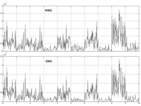
© 2017, IRJET | Impact Factor value: 6.171 | ISO 9001:2008 Certified Journal | Page 778 The power tracking can be found more in FOESC in fig 11
Fig-11 : power tracking for a wind speed of 20m/s
The power tracked by the FOESC is found more than IOESC. Thus FOESC is more efficient for maximum power tracking. The efficiency and improvement of transient response when including inner non linear controller can be verified fom [4].
7. CONCLUSION
The system employed FOESC to extract maximum power from the available wind power. The design employed an inner loop non linear controller based on FOC and feedback linearization to control the closed loop transient response with respect to the optimal turbine speed tracked by FOESC. It provides perfect input output decoupling and better than conventional FOC which increases performance robustness with respect to system parameters. Also the control strategy prevents magnetic saturation of the IG. The optimization algorithm can readily be extended to other classes of WECS without major changes. The main parameters to be adjusted are probing frequency and amplitude of the perturbing signal. A comparison is done with IOESC and FOESC is found better tracking of optimal turbine speed and power. It results in higher efficiency and since the WECS runs for a long period of time, a small improvement in power efficiency guarantees extracting a higher energy level and leads to cost reduction.
[image:7.595.317.548.84.229.2]APPENDIX
TABLE-1 : Definition of Parameters and Their Numerical Values
Blade length R 10m
Blade pitch angle 0
Air density 1.25Kg/
Turbine inertia 100 Kg
Gear box ratio 20
Stiffnes coefficient Ks 2*10^6 Nm/rad
Damping coefficient B 5*10^5 Nm/rad/s
No of pole pairs of SCIG 2
Stator leakage inductance
3.2 mH
Rotor leakage inductance
3.2 mH
Magnetizing inductance
143.36 mH
Moment of inertia of SCIG 11.06 Kg
Stator resistance 0.262 Ω
[image:7.595.42.287.103.288.2]Rotor resistance 0.187 Ω
TABLE –2 : Constant Parameters
ACKNOWLEDGEMENT
Foremost, I would like to express my sincere gratitude to my advisor Assistant Professor Swapna M of Lourdes Matha College of Science and Technology(LMCST) Trivandrum Kerala India for the continuous support of my MTech thesis study and research, for her patience, motivation, enthusiasm and immense knowledge. Her guidance helped me in all the time of research and writing of this thesis.
Besides my advisor, I would like to thank respected HOD Dr.Mohanalin Rajarakthnam and all the teachers of Electrical and Electronics department LMCST for their encouragement, motivation and help.
Last but not the least, I would like to thank my family; my parents and my brother for supporting me to complete this thesis successfully.
REFERENCES
[1] T. Senjyu, R. Sakamoto, N. Urasaki, T. Funabashi, H. Fujita, and H. Sekine, “Output power leveling of wind turbine generator for all operating regions by pitch angle control,” IEEE Trans. Energy Convers., vol. 21, no. 2, pp. 467–475, Jun. 2006.
© 2017, IRJET | Impact Factor value: 6.171 | ISO 9001:2008 Certified Journal | Page 779 [3] S. M. R. Kazmi, H. Goto, H.-J. Guo, and O. Ichinokura, “A
novel algorithm for fast and efficient speed-sensorless maximum power point tracking in wind energy conversion systems,” IEEE Trans. Ind. Electron., vol. 58, no. 1, pp. 29– 36, Jan. 2011.
[4] Azad Ghaffari, Miroslav Krsti´, “ Power Optimization and Control in Wind Energy Conversion System using Extremum Seeking”, IEEE Trans.Control Systems, vol. 22, no. 5, pp.1684 – 1695,Sep.2014.
[5] R. Cardenas, R. Pena, J. Clare, and P. Wheeler, “Analytical and experi- mental evaluation of a WECS based on a cage induction generator fed by a matrix converter,” IEEE Trans. Energy Convers., vol. 26, no. 1, pp. 204–215, Mar. 2011.
[6] B. Wu, Y. Lang, N. Zargari, and S. Kouro, Power Conversion and Control of Wind Energy Systems. New York, NY, USA: Wiley, 2011.
[7] Vinod Kumar, R. R. Joshi, and R. C. Bansa, “Optimal Control of Matrix-Converter-Based WECS for Performance Enhancement and Efficiency Optimization” IEEE Trans. Energy Convers, Vol 24, no. 1, March 2009.
[8] S. M. Barakati, M. Kazerani, and J. D. Aplevich, “Maximum power tracking control for a wind turbine system including a matrix con- verter,” IEEE Trans. Energy Convers., vol. 24, no. 3, pp. 705–713, Sep. 2009.
[9] P. C. Krause, O. Wasynczuk, and S. D. Sudhoff, Analysis of Electric Machinery and Drive Systems. New York, NY, USA: Wiley, 2002.
[10] R. Marino, S. Peresada, and P. Valigi, “Adaptive input-otput linearizing control of induction motors,” IEEE Trans. Autom. Control, vol. 38, no. 2, pp. 208–221, Feb. 1993.
[11] Hadi Malek, Sara Dadras, YangQuan Chen,” An Improved Maximum Power Point Tracking Based on Fractional Order Extremum Seeking Control in Grid-Connected Photovoltaic Systems”IDETC,CIE Portland, Oregon, USA Aug 4-7, 2013
[12] Hadi Malek,” Control of Grid-Connected Photovoltaic Systems using Fractional Order Operators” UTAH STATE UNIVERSITY Logan, Utah 2014
[12] A. I. Bratcu, E. C. Iulian Munteanu, and S. Epure, “Energetic optimiza-tion of variable speed wind energy conversion systems by extremum seeking control,” in Proc. Int. Conf. Comput. Tool, 2007, pp. 2536–2541.
[13] L. Huber and D. Borojevic, “Space vector modulated three-phase to three-phase matrix converter with input power factor correction,” IEEE Trans. Ind. Appl., vol. 31, no. 6, pp. 1234–1246, Nov./Dec. 1995.
[14] K. E. Johnson, L. Y. Pao, M. J. Balas, and L. J. Fingersh, “Control of variable-speed wind turbines: Standard and
adaptive techniques for maximizing energy capture,” IEEE Control Syst. Mag., vol. 26, no. 3, pp. 70–81, Jun. 2006.
[15] L. Y. Pao and K. E. Johnson, “Control of wind turbines,” IEEE Control Syst. Mag., vol. 31, no. 1, pp. 44–62, Feb. 2011.
[16] M. Komatsu, H. Miyamoto, H. Ohmori, and A. Sano, “Output maxi- mization control of wind turbine based on extremum control strategy,” in Proc. Amer. Control Conf., 2001, pp. 1739–1740.
[17] M. Krsti´ c and H.-H. Wang, “Stability of extremum seeking feedback for general nonlinear dynamic systems,” Automatica, vol. 36, no. 4, pp. 595–601, 2000.
[18] R. Marino, S. Peresada, and P. Valigi, “Adaptive input-otput linearizing control of induction motors,” IEEE Trans. Autom. Control, vol. 38, no. 2, pp. 208–221, Feb. 1993.
[19] T. Pan, Z. Ji, and Z. Jiang, “Maximum power point tracking of windenergy conversion systems based on sliding mode extremum seekingcontrol,” in Proc. IEEE Energy Conf., Nov. 2008, pp. 1–5.
[20] Y. Tan, D. Neši´ c, and I. Mareels, “On non-local stability properties ofextremum seeking control,” Automatica, vol. 42, pp. 889–903, Jun. 2006.
BIOGRAPHIES
JIJIN D H now working as Adhoc Assistant Professor at College of
engineering and Management
Punnapra Kerala India in the EEE Dept. Completed MTech from Lourdes Matha College of Science and Technology Trivandrum in Control Systems. Completed BTech from Govt Engineering College BartonHill Trivandrum India in Electrical and Electronics Engineering
.