© 2017, IRJET | Impact Factor value: 6.171 | ISO 9001:2008 Certified Journal | Page 1630
Design Considerations and Analysis of a Single-seated Hyperloop Pod
Pranay Mehta
1, Taheer Alarico Da Piedade Mascarenhas
21,2
Dept. Of Mechanical Engineering, SRM University, Tamil Nadu, India
---***---Abstract -
The idea of Hyperloopis to travel at high speed inlow pressure tube along with levitation. Due to presence of low pressure, the aerodynamic drag is very low thereby reducing the energy consumption. Apart from that the pod is made to levitate so as to reduce the frictional resistance. The Hyperloop Pod is designed to use Linear Induction Motor (LIM) to travel at high speed. The pod uses rotating Halbach array to levitate. Though there is low air pressure, the pod has to be designed in such a way that the choking doesn't occur.
Key Words: Hyperloop, Pod, Magnetic Levitation, Linear
induction Motor, Semi-Monocoque Chassis, Rotating Halbach Array.
1. INTRODUCTION
The Hyperloop [1] is the right solution for the specific case of
high traffic city pairs that are less than about 1500 km or 900 miles apart. Around that inflection point, supersonic air travel ends up being faster and cheaper. With a high enough altitude and the right geometry, the sonic boom noise on the ground would be no louder than current airliners, so that isn’t a showstopper. Also, a quiet supersonic plane immediately solves every long distance city pair without the need for a vast new worldwide infrastructure. However, for a sub several hundred mile journey, having a supersonic plane is rather pointless, as you would spend almost all your time slowly ascending and descending and very little time at cruise speed. In order to go fast, you need to be at high altitude where the air density drops exponentially, as air at sea level becomes thick as you approach sonic velocity.
2. STRUCTURAL DESIGN AND ANALYSIS
2.1 Chassis Design
One of the toughest hurdles to overcome while designing the pod was selection of materials. With very few options to choose from, materials shortlisted were Magnesium alloy and Aluminum alloy both providing excellent properties needed for the pod. Parallel to this was the selection of the type of chassis for the pod.
i. Monocoque Chassis. ii. Ladder Frame Chassis.
Magnesium alloy (AZ91D) was chosen above aluminum alloy due to its excellent stiffness properties for the same
cross section and also its extremely light weight. The ladder frame chassis was decided to support the entire pod.
Freezing the decision of using the ladder frame chassis, another challenge was deciding the cross section of the frame to be used.
For this an I-section was chosen as it was required to have greater resistance to major axis bending forces in the vertical plane compared to minor axis bending forces in the horizontal plane. The web was kept long and thin to increase the area moment of inertia to provide better performance using less material. The connecting linkages, in the ladder frame transmit the weight of the passenger, battery and subsystems to the main beams. The rotating Halbach array is directly connected to the main beam. The mounting bracket for rotating Halbach array is made of magnetic permeable material having good strength (Aluminum 1040). The transverse members are fixed at locations where large loads such as the passenger and battery are concentrated or at extremities to reduce bending along the minor axis. The Dual Single LIM is mounted at the bottom of each rail of the ladder frame chassis using fixtures.
In order to further increase the stiffness of the chassis, strain hardening can be done and heat treatment operations such as quenching can be employed. But it must be ensured that the stress does not surpass the ultimate stress value as the fracture in such brittle material would be sudden and without much warning due to less strain produce for large amounts of stress.
2.2 Material Selection
© 2017, IRJET | Impact Factor value: 6.171 | ISO 9001:2008 Certified Journal | Page 1631 excellent material to be used as a shell for the pod. The grade
of carbon fiber to be used is Hexcel ® IM10.
Stiffness
Chart -1: Comparison of Stiffness of different materials for the same cross-section.
2.3 Pod curvature calculations
The stress was given on the fact that the pod experiences minimum external vibration environments whilst moving. This could be fulfilled only by having a laminar or near laminar air flow over the pod, which can be achieved via various methods. At the same time, keeping into mind the Design for Manufacturing, and tangent ogive nose satisfying all of the above conditions, we decided to go for a TANGENT OGIVE NOSE CONE, designed only for a semi-circular part. Thus, according to the following equations where R = Radius of curvature (mm); C = Caliber; L = Length of the cone (mm);
d = Diameter of the cone (mm).
[image:2.595.46.278.136.312.2]………...(1) ………...….(2) ………(3)
Figure 1: Pod Side Profile with dimensions.
Equation (1) gives us the circle on which the pod’s nose is tangent to (hence tangent ogive nose). Equation (2) gives us the radius of the circle on which the pod’s profile is to be sketched. Equation (3) gives us the ratio of the length and the diameter of the nose cone.
In this case, the length for the fore part of the pod was decided to be 2136mm and the diameter of the nose cone was decided to be 800mm. Also, the rear part of the pod was designed using the same set of equations. The radius of curvature for the nose of the pod is calculated as 3037.51mm. Similarly, using the same set of equations, the longitudinal curvature of the pod as shown in the Image below , was obtained.
Figure 2: Pod top view with dimensions.
The radius for the longitudinal curvature was obtained as 4215mm.
2.4 Kantrowitz Limit
Let’s consider the pod travelling in the closed tube. As the pod is starts travelling the air starts flowing around it adding to drag. If the speed of pod is very high, it will not allow the air to flow completely around it and it starts accumulating in front of it, higher the speed, higher is the air accumulation in front. After one stage the air accumulated in front reaches a high pressure and preventing the pod to move further, this is called as choking. The maximum speed by which the pod can achieve is called as Kantrowitz limit [3]. The Kantrowitz limit
depends only on the cross section of the body in the tube.
The Kantrowitz limit is given as follows:
[image:2.595.308.560.276.397.2]© 2017, IRJET | Impact Factor value: 6.171 | ISO 9001:2008 Certified Journal | Page 1632 Figure 3: Cross-section of the Pod inside the tube
for the design of the pod.
Graph-1: Graph of Bypass ratio v/s M
The Kantrowitz equation is valid only if
Therefore, the kantrowitz limit is considered only if
From this it is inferred that irrespective of the design of pod, the flow will not choke till Mach0.37. From the Graph 1, for pod, the maximum possible Mach number to achieve is 0.53.
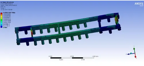
2.5 Analysis
Structural and Flow analysis was done on the pod with all the subsystems (Propulsion, braking Levitation and
electronic) in place. The pod was subjected to two main phases - stationary phase and accelerating phase. All analysis was done on ANSYS Release 14.5.
Figure 4: Total Deformation of the Ladder Frame Chassis
Figure 5: Total Deformation of the complete pod during accelaration
Figure 6: Total Deformation of the complete pod while stationary
[image:3.595.309.560.145.260.2]Boundary conditions for Flow analysis using Ansys Fluent were : Inlet pressure: 860 Pa and Velocity: 505 km/h.
[image:3.595.310.568.614.741.2]© 2017, IRJET | Impact Factor value: 6.171 | ISO 9001:2008 Certified Journal | Page 1633 Figure 8: Top view- Flow analysis
The results that were obtained were 7.9mm deformation during acceleration via pusher and 0.12mm while static and were satisfactory.
After calculations, the Coefficient of drag turned out to be 0.008, which was excellent. This meant that the value was significantly lower and that the pod would face the minimum air drag (calculated around 100N).
3. DESIGN OF LINEAR INDUCTION MOTOR (LIM)
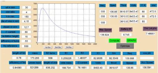
While designing the LIM[2], it was found out that the bigger
the diameter of wire, the lower is the resistance offered by the wire and lower is the no of turns possible; this also allowed to carry higher current as ampacity of bigger diameter wire is more. The major drawback with using bigger gauge wire was that less no of turns were possible, which thus decreased the thrust. A higher value of N (number of turns) * I (current) is required for a better thrust. The best possible gauge of wire for the best thrust could be obtained by plotting N * I and the Diameter of the wire ( ). Thus a graph between N * I and the wire diameter was plotted in MATLAB.
Graph 2: N*I v/s wire diameter
If a wire of lower diameter and higher resistance was to be used, this would increase the joule heating and thus causing the increase in temperature of the system and thus leading to loss of magnetism due to heat. This would also create problems to other subsystems. So, after doing several
calculations, it was understood that choosing a wire diameter of higher gauge would be better. So, AWG4 gauge wire was chosen.
On doing several iterations in MATLAB the following design of LIM was considered to be the best solution. The pod would be using 2 LIM’s on both of its sides, each LIM contributing to roughly 3500N and pushing the pod to a highest speed of 138m/s.
Figure 9: Optimized result obtained from MATLAB code
3.1 THERMAL ANALYSIS ON LIM
The thermal analysis becomes important whenever there is a magnetic field because the magnetism tends to deplete with temperature due to curie effect. In Hyperloop, the major cause of heat generation is current flowing through LIM. There is no or very little air in the tube hence the convection is also negligible. The heating effect due to current was analysed in ANSYS.
The acceleration of pod was decided for 30 seconds, hence it would be expected that the temperature will not rise significantly.
For analysis the boundary conditions were calculated using following equations. Here, = Heat generated per volume; heat flux and R = resistance.
……… (4)
……… (5) (6)
Boundary conditions applied:
i) External temp = 300K ii) Heat flux from equation (6)
[image:4.595.36.287.550.665.2]© 2017, IRJET | Impact Factor value: 6.171 | ISO 9001:2008 Certified Journal | Page 1634 Figure 10: Thermal Analysis of pod
4. CONCLUSIONS
The advantage of Hyperloop is that the net resistance offered to motion is very less as there is minimal air drag, minimal friction. It could be seen that the air drag was less than 100N. The choice of carbon-fibre as the material of the shell and magnesium alloy for the ladder frame chassis was made to reduce the weight of the overall pod by 100kg as opposed to the use of aluminium and steel. Once the top speed is reached, only a force of 100N is needed to maintain the speed, which is very less. If a pusher was to be used that initially pushes the pod to very high speeds, then we would require LIM to provide a thrust just enough to overcome drag. If we design a LIM to give only 100N thrust, the power requirement would be very low, and hence it could be easily being achievable with batteries. Because of lower thrust the weight of the LIM would also be very less. On observing all the results it could be concluded that the Hyperloop Pod can be manufactured with ease and is capable of reducing travel time by a significant amount.
REFERENCES
[1] Elon Musk, SpaceX, “Hyperloop Alpha” – white paper.
[2] Sarveswara Prasad Bhamidi, “Design of a single sided linear induction motor (slim) using a user interactive computer program-Thesis presented to the faculty of the Graduate School, University of Missouri-Columbia”.