© 2017, IRJET | Impact Factor value: 6.171 | ISO 9001:2008 Certified Journal | Page 975
Computational Fluid Dynamic Analysis and Structural Analysis of
Ribbed Panel Structure using FEA
Maqsood Ali
1, Dr. L. Chandrasagar
2, H S Manjunath
31
Department of Mechanical Engineering, Dr. Ambedkar Institute of Technology Bengaluru, Karnataka, India
2Professor Department of Mechanical Engineering, Dr. Ambedkar Institute of Technology Bengaluru,
Karnataka India
3
Assistant Professor Department of Mechanical Engineering, Dr. Ambedkar Institute of Technology Bengaluru,
Karnataka India
---***---Abstract -
Stress analysis is very important to find thestructural safety of the engineering components and assembly. Initial estimation helps in designing the structural properly. Due to the advances in the finite element numerical technology and its application software’s are becoming good tools for the designer for find the best design set out of many possible designs with in short time. In the present work, computational fluid dynamic analysis is carried out to find the impact velocity and pressure conditions on the object. Fluid141 element is used for representation. After application of boundary conditions, the results show maximum pressure development of 870N/m2and velocity of 45m/sec on the wall surface. These values are considered for designing the thickness of the plate. But the results shows compared to the impact load, the burst pressure requires more thickness. The calculations show a thickness requirement of 30mm for the problem. But design optimisation is carried out with section elements which shows with 83.15mm height with 2mm thickness can give the same moment of inertia of solid section. The results show complete safety for the given loading conditions. Later the plates are analysed using shell elements which also shows safety under given loading. Transient analysis is carried out on the top panel, as it is made of single panel unlike other structure which are centrally ribbed and contains two layers. The transient results shows safety of the component, but the values of stress and deformation are increasing. Shell63, mass21, Beam188 and RBE3 elements are used for solving the problem.
Key Words
:
Engineering components, Computational fluid dynamic, Impact velocity and pressure, burst pressure, Inertia of solid section, Shell elements, Transient analysis1. INTRODUCTION
Structural analysis is the key aspect of engineering design. Proper structural analysis helps in finding the stress condition and it helps proper design optimization of the structure. Various structural analysis are as follows.
Static Analysis
Modal Analysis
Harmonic or cyclic analysis
Transient Response analysis
Spectrum Analysis
Thermal Analysis
Computational Fluid Analysis
Probabilistic analysis
Static analysis is mainly concentrated about finding the stress and deformation condition of the problem. Modal analysis is to find the fundamental frequencies to find the resonant condition of the problem. Harmonic analysis is to find the frequency plots and phase plots in the problem. Transient response is applied to find the maximum amplitude of displacement for the given load history curve. Spectrum is a probabilistic analysis which gives in terms of percentage of safety. Thermal analysis is to find the temperature condition of the problem. Computational dynamic analysis is a wide field applied to many branches of engineering from single phase analysis to multiphase analysis. Similarly loads can be transferred to structural or vice versa can be carried out CFD analysis. It is the most applied analysis for many engineering application. Car, aero plane body design are the simple example of CFD applications.
1.1 Stress Analysis
Stress should be always less than the allowable stresses for structural safety. Various theories of failures are applied to find the structural safety. They
Maximum principal Stress theory (Rankin’s theory)
Maximum Shear Stress theory(Tresca’s theory)
Vonmises Theory(Maximum Distortion energy Theory)
Here maximum principal stress theory can be applied to brittle materials as it gives the nature of stress. Maximum shear and vonmises theories can be applied to ductile materials.
1.2 Impact Loading:
© 2017, IRJET | Impact Factor value: 6.171 | ISO 9001:2008 Certified Journal | Page 976 can be avoided by replacing dynamic load to equivalent static
[image:2.595.343.520.151.282.2]loads. Various formulae’s are available for this calculation. Some of the formulations are represented below.
Fig 1.1: Body under Impact
2. PROBLEM DEFINITION AND FINITE ELEMENT
MODEL DEVELOPMENT
Computational fluid analysis and theoretical design of section and final assembly analysis using finite element analysis is the main definition of the problem.
The main objectives include
Computational Fluid dynamic analysis for the pressure and velocity conditions
Transient response of the plate structure
Stress condition of the panel members
2.1 Methodology
Computational Fluid Dynamic Analysis to find maximum pressure for the Given Velocity of the projectile
Sectional design based on the CFD results and design pressure specified
Geometrical modelling and Meshing
Analysis for structural safety
Transient response analysis for the top frame members2.2 Design Considerations
Deflection should be as per the IS codes for plate design
Overall deflection in the assembly should be less then 15mm.
Burst Pressure =0.3bar
Allowable Stress for the plate/Assembly Material: 300Mpa
The dimensions of the plates are limited by 1meter in length and one meter width
2.3 CFD analysis
Analysis has been carried out for a dimension of 3meter in length and 3 meters in width. The blast particles with angle orientation 45 degrees hit the outer object. The weight
[image:2.595.337.519.153.445.2]of the mass particle is 5 kg for the maximum extent. Along with this the plate is subjected 0.3 bar pressure due to testing environment. Initially CFD analysis is carried out to check the pressure development on the object.
[image:2.595.341.519.297.460.2]Fig 2.1: Geometry of the Plate
Fig 2.2: Meshing and application of Boundary conditions.
Boundary conditions are essential in the numerical analysis. Here in the CFD, the degree of freedom is more compared to the structural elements. Structural elements are limited by maximum 6 degrees of freedom. But for the fluid elements, degree of freedom can be increased up to 14. These include velocity in the three different direction, pressure, and temperature along with structural degree of freedom.
[image:2.595.338.523.590.733.2]© 2017, IRJET | Impact Factor value: 6.171 | ISO 9001:2008 Certified Journal | Page 977 Fig 2.4: Vector plot of Velocity
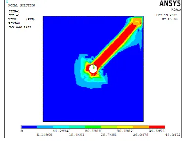
Fig 2.5: Pressure plot under CFD Loading
Maximum pressure on the wall boundary is 870N/m2.
2.4 Calculations for finding the thickness of the
panel
Considering a distributed load on static loading conditions
Pressure acting on the body: 870N/m2
Total Load acting on the plate F = 1*1*870=0 .870N
This impact load as per the CFD analysis moves at 46.34m/sec.
Calculation of Static equivalent dynamic load:
M*V=F*t
Here maximum mass of the particle M=5kg
V=46.34m/sec
F is unknown value
t = 0.01 Seconds
5*46.3=F*0.01
Dynamic equivalent static load F=23150N
So structure should be designed to take a load of 23150N under static equivalent dynamic loads
[image:3.595.337.523.94.206.2] So a standard size of 30mm can be considered.
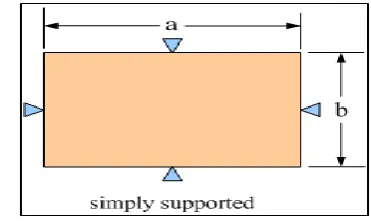
Fig 2.6: Simply Supported Conditions for Plate
[image:3.595.330.532.272.397.2]Considering the dynamic equivalent static load the thickness required based on simply supported configuration is
Fig 2.7: Simply Supported plate with a point Load
2.5 Geometrical Built up of the Problem
Fig 2.8: Geometry of the Problem
[image:3.595.335.535.461.606.2]© 2017, IRJET | Impact Factor value: 6.171 | ISO 9001:2008 Certified Journal | Page 978 Fig 2.9: Back view of the Assembly
[image:4.595.307.566.96.211.2]The back side of the structure is mainly made of door structure. The door structure is assembled to the main structure by hinges. 18mm bolts are used for assembly. Each panel is assembled by two bolts. The red colour region shows construction of door structure. 10 meters width of the structure can be observed.
Fig 2.10: Door Attachment to the inner panel Structure
The doors are mainly used for opening and locking of the structural assembly. All these structures need to with stand the load of burst pressure as well as the dynamic impact loads. The attached bolts and panel structure should with stand these loads. Structural safety is the utmost important consideration in the geometrical built up of the problem.
[image:4.595.308.560.249.367.2]Fig 2.11: Selected View1 for the Assembly
[image:4.595.74.238.343.472.2]Fig 2.12: Selected View 2 for the Assembly
Fig 2.13: Selected View 3 for the Assembly
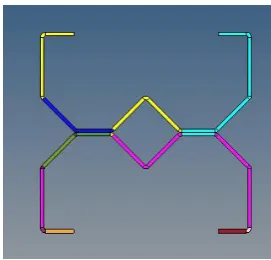
Further section used in the problem are represented as follows.
Fig 2.14: Geometry of Middle Section
2.6 Meshing Of the Geometry
[image:4.595.365.501.438.568.2] [image:4.595.43.321.608.733.2] [image:4.595.58.524.611.747.2]© 2017, IRJET | Impact Factor value: 6.171 | ISO 9001:2008 Certified Journal | Page 979 The figure 2.15 shows mesh view of the problem. Mesh
[image:5.595.345.517.120.231.2]is life of the structural analysis. This converts geometrical form to mathematical form for executing the problem to find the unknowns. Shell elements and beam elements are mainly used for the problem. Beams are mainly used as bolt members. RBE3 element is used for connection element. Total of 423836 elements with 539284 nodes are used to represent the problem.
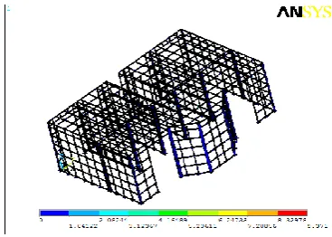
Fig 2.16: Mesh of Frame Structure
[image:5.595.66.257.197.321.2]The figure 2.16 shows mesh of only frame structure. Since frames are essential elements of load carrying under burst pressure as well as impact loads. They should be sufficient rigid to take the loads.
[image:5.595.52.274.414.539.2]Fig 2.17: Mesh View for the Assembly
Fig 2.18: Mesh View for Assembly
2.7 Element Types used in the problem
Shell63 ElementFig 2.19: Shell63 Element
Shell63 is linear element suitable for thin geometry analysis. It is defined with 4 nodes and has six degree of freedom at each node. The degree of freedom is concerned to three translations and three rotations.
Beam188 Element:
Beam188 element is suitable to model regular or irregular geometries. Even irregular members are also can be represented. It is suitable for both linear and nonlinear problems. It is defined with one more additional node for change of direction.
2.8 Assumptions
Material is assumed to be homogenous and free of any voids and defects
Isotropic properties are assumed for the problem
Linear shell element is used for analysis
Analysis is done with in elastic loading conditions
All Finite element approximations are applied to the analysis
3. RESUTLS & DISCUSSION
Initially analysis has been carried out for pressure load throughout the structure. Due to difficulty in analysing the huge structure, the plate elements are hidden from the display. The frame structure results are as follows. [image:5.595.341.525.628.759.2]
© 2017, IRJET | Impact Factor value: 6.171 | ISO 9001:2008 Certified Journal | Page 980 The maximum deflection developed in the frame is only
[image:6.595.332.530.92.218.2]9.371mm which is less than the allowable deflection of the problem. So the structure is safe for the given loads.
Fig 3.2: Vonmises stress in the Assembly
This stress is less than the allowable stress of 290Mpa for the problem. So the structural assembly is safe for the given loading conditions.
[image:6.595.56.269.138.286.2]
Fig 3.3: Deformation in the Central Panels (Maximum Deflection: 9.371mm)
[image:6.595.339.525.251.377.2]Fig 3.4: Vonmises Stress in the Central Frames
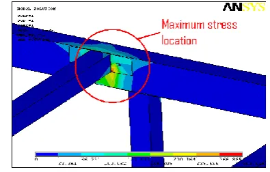
[image:6.595.52.271.366.518.2]Fig 3.5: Maximum Stress Location in the Central Panels
Fig 3.6: Vonmises Stress in the Right Section (Maximum Stress: 235.364 Mpa
)
Fig 3.7: Deflection in the Front and Side Panels (Maximum Deflection: 11.13mm)
4. CONCLUSIONS
The panel structural assembly is modelled and analysed for structural safety using Finite element analysis. The summary of results is as follows.
Initially computational fluid analysis is carried out to find the velocity and pressure conditions of the problem. Fluid141 element is considered using Ansys / Flotran software. The results show maximum pressure as 0.0087bar and velocity as 45.67 m/sec.
[image:6.595.334.531.428.572.2] [image:6.595.57.267.564.710.2]© 2017, IRJET | Impact Factor value: 6.171 | ISO 9001:2008 Certified Journal | Page 981 The results shows burst pressure has more requirement
of thickness compared to the CFD analysis pressure condition. So further analysis is carried out with burst pressure as specified in the design conditions.
Theoretical calculations are carried out to find the sectional requirement and optimisation. The optimisation shows, the same moment of inertia obtained through solid section can be obtained through a box section with after certain iterations. By this weight of each panel can be reduced from 234kgs 33.36 kgs. So a greater optimisation can be carried out by proper selection of suitable section.
Further assembly is done using Catia software and meshing is carried out. The connections are done by both RBE3 elements and coupling elements. The bolts are represented by Beam188 elements. In the initial analysis due to complexity of meshing and executing such large assembly, each plate meshed by one element to reduce the number of elements. Only frame structures are meshed using 25mm as the size of the element.
The results shows complete safety of the assembly as obtained results shows both stress and deformations are well within the limits.
Later the plate structures are analysed separately for the given loads. The results show the development of stress and deformation are well within the range.
Transient analysis is carried out for the top panel as it is single layer construction. The results for transient analysis shows increase of stress and deformation compared to the static conditions, but still the structure shows complete safety for the given loading conditions.REFERENCES
1. Duffin R. J “ Geometric Programming Theory and Applications”, Wiley publishers, New york, 1960,
2. Morris A. J., “ Foundations of Structural Optimisation – A unified Approach”, John Wiley & sons, UK, 1960.
3. Gettatly, “A procedure for Automated Minimum Weight Structural Design”, Aero quart, Part 1, Vol, 17, pp 332-342, 1999.
4. Jim Patterson, Hendrickson, “Trailer Suspension Systems”, 2000
5. Hursh Narayan, Robert Bosch Corporation, 2002
6. Joe Metrisin, Florida Turbine Technologies ,2002
7. Arrora, “Introduction to Optimum Design’, 2nded,
Academic Press, 2004