© 2018, IRJET | Impact Factor value: 6.171 | ISO 9001:2008 Certified Journal | Page 2695
Parameter Comparison of Online and Offline MPPT Algorithm Review
Kathiresan .R
1, S.E. Murthy
2, S. Mohanvel
3, Dr. T.K. Santhosh
41, 2, 3Assistant Professor, Knowledge Institute of Technology, Salem. 4Associate Professor,, Knowledge Institute of Technology, Salem
---***---Abstract-The worldwide demand for electrical power is
increasing constantly. Fossil fuel production is reducing and goes for alternative renewable energy sources. Solar PV array is another alternative energy resource, but the maximum output power generation in PV array varies with irradiance and atmospheric condition. The efficiency of power generation very low, it requires MPPT control techniques. An MPPT method is the automatic control algorithm (or) technique to adjust the power interface and partial shading and achieve the greatest possible power harvest during moment to moment variations of irradiance and atmospheric condition. This paper reviews different types of MPPT techniques like Perturb and observe, Incremental conductance, soft computing techniques. Each of the methods parameters compared in terms of (i) Tracking speed (ii) Algorithm complexity (iii) Dynamic tracking response under partial shading condition (iv)Hardware implementation.
Keywords: MPPT, Soft Computing, Photovoltaic, Hybrid
INTRODUCTION
Photovoltaic Power (PV) plays crucial role in renewable energy power generation and their power essential now days due to shortage and environmental impacts of conventional fuels. In the future PV power will have more importance due to the reducing of fossil fuels and their environmental impacts. The main disadvantage is the low efficiency of energy compared with other renewable energy resources. The PV is a non-linear source that depends on atmospheric temperature and irradiation level. Therefore Maximum Power Point Tracking (MPPT) is introduced to extract the maximum power from the PV array. Various MPPT algorithms have been developed to improve the PV array efficiency. These algorithms differ from each other on the parameter, Chosen Convergence speed, sensors used, complexity and implementation cost. These MPPT algorithms are to achieve faster and accurate tracking performance and reduce the oscillations around MPP. Every algorithm categorized depend on the control variable it uses 1). Voltage 2). Current 3). Duty cycle. P&O algorithm is the most popular methods, in this algorithm less complexity in comparison with other MPPT algorithms. It is not preferred for high power applications. During dynamic state P&O suffered due to repeated perturbation and power oscillations around the MPP. To avoid this problem conventional step size is altered as fixed step size, due to this change PV system produce better output performance. A variable perturbation size algorithm is suggested into normal conventional P& O algorithm from these changes to reduce the oscillations and improved the system response speed. Incremental conductance technique is widely used and tracking accuracy
is good at steady state and good adaptability to the rapidly changing atmospheric conditions. To improve both the MPPT speed and accuracy a modified dynamic change in step size for incremental conductance. This technique improves the system performance but cost is increased. Incremental Conductance method presents difficulties to adjust the step. The size of the step will determine the tracking speed, when the step size is large, the system response is fast, but the solar system may work around the real maximum Power Point and cause oscillations.
In constant voltage method an approximate linear relation between Vmpp and Voc is followed. Although this method is lucid, the exact MPP cannot be tracked and it utterly fails when change in irradiation occurs. Methods like HC follow a primitive approach to track MPP. It compares the present with previous power values and updates the duty cycle accordingly. However, this procedure is rendered ineffective in varying atmospheric conditions and its performance largely depends on the step size.
OFF LINE METHODDS
It is model based method. Usually the physical values of the PV system panel are used to generate the control signals. It require to one (or) two of the solar panel values.
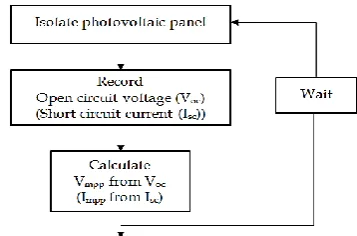
Open Circuit Voltage method (OCV)
It is simplest offline methods. This method uses the approximate linear relationship between the open circuit (Voc) and the maximum power point voltage (Vmpp) under atmospheric conditions.
Vmpp≈KVoc Where K-constant
[image:1.595.346.525.624.742.2]K depends on the solar cell characteristics
© 2018, IRJET | Impact Factor value: 6.171 | ISO 9001:2008 Certified Journal | Page 2696 This constant value is empirically derived based on
measurement of Vocc and Vmpp under different environmental conditions. K range-0.73 to 0.80 has been reported in polycrystalline PV modules. In these methods have some drawbacks 1). MPP may not be tracked accurately 2).Measurement of Voc requires partial shadding of the load.3).This interferes with circuit operation and will cause more power losses. To prevent this loss of power, pilot cell has been used to obtain Voc. Chosen of Pilot cell carefully.
Short Circuit Current method (SCC)
Approximately linear relationship between the short circuit current of the solar panel and MPP current (Impp)
Impp≈KIsc
K=0.8 and 0.9 values. Load should be shed in order to determine the Isc. This method has some advantages, more accurate and efficient than the OCV method. Power losses associated with load interruption can be avoided, if measurement of the temperature and irradiance is employed to estimate the SCC based on the governing model equations OCV and SCC methods fail to deliver maximum output power to the load for following reasons.Load interruption occurring during measurement of Isc (or) Vsc. MPP can never be tracked quite exactly using these methods. Two methods cannot be categorized as “true seeking” MPP method.
ONLINE METHODS
In online methods, usually the instantaneous values of the PV attempt output voltage (or) current are used to generate the control signals. The generated control signal is applied to the PV system along with a small methodical and predicated perturbation in voltage (or) current (or) duty cycle and the resulting output power is determined. By analyzing response of perturbation on output power of PV panels, the direction of change (decrease (or) increase) of the control signal is determined.
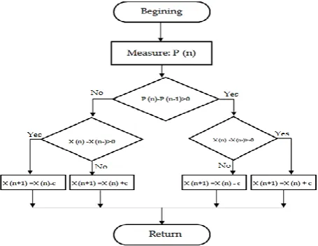
Perturbation and observation (P& O)
It operates by disturbing the voltage of the panel periodically by comparing the energy previously delivered with those after disturbance. Concept –When the MPP is reached –tracker will oscillate around it. Resulting in a less of PV available power, especially in perturb atmospheric condition with constant (or) slowly varying changes. By else, In case of rapid changes of atmospheric condition (e.goccurrences of cloud) changes of solar radiation. P& O algorithm deviates from the MPP until a slow solar radiation change occurs (or) Settles down. This method has following drawbacks 1). Amplitude of the perturbations applied to the system is the main factors determining the amplitude of oscillation as well as convergence rate of the MPP. The larger the perturbation will lead to a higher value of oscillation amplitude .Small-perturbation, oscillation – reduced, but the rate of convergence will decrease as well. To overcome this disadvantages use of variable perturbation
[image:2.595.310.538.148.324.2]size that gets smaller. Now MPP is approached was proposed. Magnitude of the variables perturbation is determined based on the slope of the power –current curve.2). If the system operating point changes quickly, the algorithm will be prone to tracking errors.
Fig.2. Flow Chart of Perturbation and observation algorithm.
Improved P& O Methods.
Extremum Seeking Control Methods (ESC)
This method applied in various applications such as traction maximization in 1).Antilock braking for a car 2).Power reduction maximization of a flight 3).Pressure rise maximization of an aero engine compressor 4).Autonomous vehicles target tracking 5). PID Tuning.
Algorithm
Sinusoidal current =a Sin(wt) perturbation will be added to the reference current (Iref) and applied to the PV systems. In ths algorithm have two conditions i). If the resulting ripple in the current is in phase with the output power ripple, the output power will fall to the left of MPP. Reference current (Iref) will less than (Impp). Controller will increase the reference current. ii).The ripple in the current is out of phase with that in the output power. Output power will fall to the right of MPP and reference current will be larger than Impp. Controller decreases the reference current until MPP is reached.
RIPPLE CORRELATION CONTROL (OCC)
© 2018, IRJET | Impact Factor value: 6.171 | ISO 9001:2008 Certified Journal | Page 2697 perturbation. This approach does not require any
parameterization (or) structural formalization of the modeling uncertainty. This method has some drawbacks 1).Complexity in the implementation.2). Necessary to evaluate signals of relatively low amplitude.
1). Fixed adaptive P& O
Reference signal was generated by a fixed perturb for outer control loop. Perturb signal either voltage (or) current from PV array. This system operates according to the previous data. Drawbacks of this type 1. Tracking is slower for smaller perturb step .Where, tracking is quicker for large perturb and oscillations were present.2. To overcome this difficulty modified fixed perturb is used. Here duty ratio as the perturb step rather than PV array current (or) Voltage.3. This algorithm produces oscillations in most the case.The Main disadvantage is computational problem for heavy loading conditions. The perturb depends on open circuit voltage which gets varied based on atmospheric conditions.
2). Variable Step Size P&O
Here duty cycle was adjusted according to perturb size. In this technique perturb changes control variables and compares the output PV Power with the Previous perturb step. This method operates under rapidly changing environment and faster response.
3). Multi Variable P& O
This method uses many perturb variables instead of one variables. To extract more power from PV. Initially this methods work as a conventional P& O Method to track the MPP. If sign of perturb is changed –conventional P&O Cannot Support. System will manage the variables and perturbations which lead to the best operating point in steady state conditions.
Drawbacks
It is complexity when compared to conventional method
4). Variable perturbation size adaptive P& O
To track the maximum power under rapidly changing condition.
This method uses 3 algorithms
1). Current perturbation 2). Adaptive Perturbation 3). Variable Perturbation
Current Perturbation
To boost up the tracking performance by considering current as a variable instead of voltage.
Adaptive Perturbation
To make operating point near to the MPP and follow the concept of a Fractional Short Circuit Current (FSCC). It operates under rapidly changing irradiance.
Variable Perturbation
To reduce the oscillation present around MPP using a fine tuning method.
5). PSO based P & O
A combined of P& O and Particle Swarm Optimization (PSO) to track the MPP under partial shading condition of PV system. Initially P& O algorithm is operating to track the local Maximum Point (LMP).During partial shading condition PSO algorithm is used to the Global Maximum Point (GMP).
Drawback
PSO have larger iteration time by combining both time reduced to track the MPP and also searching space of the PSO gets Reduced.
6). P & O based by hybrid MPPT
It is combined of hybrid P&O algorithm and the open circuit voltage. Here set point approximation is made using open circuit voltage. Exact maximum power point is tracked using P& O algorithm. Temperature and irradiance, MPPT has been estimated through the thevenin theorem. Online phase P&O algorithm is used to track the Maximum power point. Conclusion is implementation cost is high. Cost depends on measurements of direct temperature and irradiance.
1). Modified INC
This technique is used to track MPP under both partial shading and load variation with fast response in tracking. It operated based on multi duty cycle control method. Multiple peaks are obtained during partial shading condition and the algorithm will separate the peaks into GMP and LMP. Converter duty cycle step size value acts as a control variable.
2). Variable step size INC
© 2018, IRJET | Impact Factor value: 6.171 | ISO 9001:2008 Certified Journal | Page 2698 3).Improved variable step size INC
It is combination of variable step size along with incremental Resistance (INR). To improve the response speed and accuracy of the MPPT in the PV system. Control variable-Current. Tracking simple and efficient under– dynamic conditions. INR based MPPT is operating in both fixed and variable step size modes.
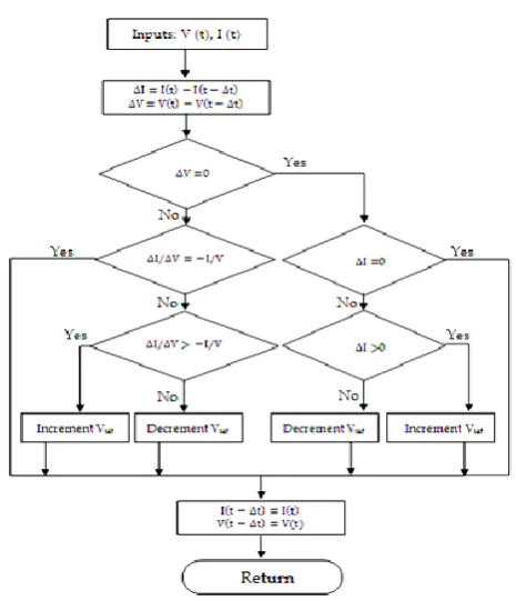
MPP tracking applying IC algorithm follows three common
steps:
1. When=dP/dV =0 the error is zero andVmpcan be achieved
2. WhendP/dV>0, (i.e.,)dP/ dV> -I/ V, the MPP is dragged towards the left of the curve (error is positive)
3. WhendP/dV<0(i.e.,)dP/dV< -I /V , the MPP is dragged towards the right of the curve (error is negative)
4).Power incremental based INC
This method describes the INR algorithm which operates under three methods
1) Variable frequency constant duty control (VFCD ) 2) Constant frequency variable duty control ( CFVD ) 3) Threshold tracking zone (TTD ) for obtaining
reference point
TTZ divided as two types
1) Conductance threshold Zone ( CTZ) 2) Power threshold Zone (PTZ )
Power increment MPP tracking is done in two modes
1). Tracking inside TTZ
INC tracking is significant, Primary measure is ∆c for PI –INC MPPT.
2). Tracking outside TTZ
PI tracking is significant, Primary measure is ∆P for PI-INC MPPT.
5). Modified adaptive INC
[image:4.595.313.546.73.344.2]Duty cycle ratio is not considered as constant. Variable step size is used to improve the response of tracking and to reduce power oscillation around MPP. When step size Increase the system operates far away from MPP. When Step size decrease the system operates near MPP.
Fig.3. Flowchart for Incremental Conductance algorithm
Intelligent MPPT Techniques
Most researchers used soft computing techniques in the control unit of MPPT to track the MPP with fast response and reduced fluctuation.
Fig.4. Flow diagram of fuzzy inference system.
It is operated using membership functions instead of mathematical model
It consist of three stages
1). Fuzzification
2). Inference mechanism
[image:4.595.310.566.461.601.2]© 2018, IRJET | Impact Factor value: 6.171 | ISO 9001:2008 Certified Journal | Page 2699 During Fuzzification
The input variables are converted into linguistics variable according to the chosen membership function.
Inference Mechanism
The linguistics variable gets manipulated based on the rule base which defines the behavior of the controller
Defuzzification
Fuzzy logic controller output is converted from a linguistics variable to a numerical variable still using a membership function. This provides an analog signal that will control the power converter and drive the operating point to the MPP. FLC based MPPT has two inputs and one output usually the inputs are tracking error ( E ) and change in error (∆E )
E(n)=P(n)- P(n-1) V(n)- V(n-1) ∆E(n)= E(n)-E(n-1) Where n-sampling time
P(n)- Immediate power of PV system V(n)- Immediate voltage.
Advantages
1). Fast convergence
2). Ability to handles non linearity 3). Works with in imprecise inputs
4). Provides approximated outputs based on trial and error approach.
5). Lack of requirement of an accurate mathematical model. 6). Learning ability and accuracy depend on the fuzzy levels and form of membership functions.
Most of the fuzzy systems memberships have fuzzification and defuzzification
Neural network based MPPT
Popular for system identification and nonlinear system modeling applications.This technique is used to solve the problem using parameter approximation. It consist of three layer
1). Input 2).Hidden 3). Output
Input layer
It consists of two neurons which are fed by the voltage and current variables from the PV system.
Output Layer
It is a duty cycle which is used to drive the converter operates at (or) near the MPP.
Hidden Layer
It is used to propagate the input signals to the output layer based on the transfer function applied on it. Determination of number of neurons in the hidden layer is not identified completely. For optimal solution number of hidden neurons is chosen based of trial and error combination. From literature identified tangent sigmoidal function is used in hidden layer. Pure linear function is used at output layer.
Advantages
Trained network can provide accurate MPP without requiring more knowledge about the PV parameter.
Disadvantages of PV system
[image:5.595.309.558.401.586.2]Higher cost required for generation of energy as compared to that produced by conventional power generation system. Efficiency is low.
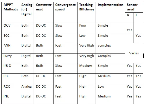
Table 1 Detailed analysis of online and offline methods
CONCLUSION
© 2018, IRJET | Impact Factor value: 6.171 | ISO 9001:2008 Certified Journal | Page 2700
REFERENCES
[1]. Abdelsalam Ahmed K, Massoud Ahmed M, Shehab Ahmed, Enjeti Prasad N.High-performance adaptive perturb and observe MPPT technique for photovoltaic-based micro grids. IEEE Trans Power Electron 2011;26(4):1010–21.
[2]. Al-Amoudi A, Zhang L. Optimal control of a grid-connected PV system for maximum power point tracking and unity power factor. In: Proceedings of the 7th international conference on power electronics variable speed drives; 1998. p. 80–85.
[3]. Zhang L, Al-Amoudi A, Bai Y. Real-time maximum power point tracking forgrid-connected photovoltaic systems. In: Proceedings of the 8th internationalconference on power electronics variable speed drives; 2000. p. 124–129.
[4]. Khaehintung N, Wiangtong T, Sirisuk P. FPGA Implementation of MPPT using variable step-size P&O algorithm for PV applications. In: Proceedings of the IEEE International Conference on ISCIT; 2006. p. 212–215.
[5]. Petrone Giovanni, Spagnuolo Giovanni, Massimo Vitelli. A multi variable perturb-and-observe maximum power point tracking applied to a single-stage photovoltaic inverter. IEEE Trans Ind Electron 2011;58(1):76–83.
[6]. Kumar KollimallaSathish, Kumar Mishra Mahesh. Variable perturbation sizeadaptive P&O MPPT algorithm for sudden changes in irradiance. IEEE TransSustainEnergy 2014;5(3):718–28.
[7].Lian KL, Jhang JH, Tian IS. A maximum power point tracking method based on perturb-and-observe combined with particle swarm optimization. IEEE J Photo volt 2014;4(2):626–33.
[8]. IshaqueKashif, Zainal Salam. A deterministic particle swarm optimization maximum power point tracker for photovoltaic system under partial shading condition. IEEE Trans Ind Electron 2013;60(8):3195–206.
[9]. Moradi MH, Reisi AR. A hybrid maximum power point tracking method forphotovoltaic systems. Sol Energy 2011;85:2965–76.
[10].Moradi MH, Tousi SMR, Nemati M, Basir NS, Shalavi N. A robust hybrid method for maximum power point tracking in photovoltaic systems. Sol Energy2013;94:266–76.
[11]. Park Sang-Hoon, Cha Gil-Ro, Jung Yong-Chae, Won Chung-Yuen. Design andapplication for PV generation system using a soft-switching boost converterwith SARC. IEEE Trans Ind Electron 2010;57(2):515–22.
[12]. Al Nabulsi Ahmad, Rached Dhaouadi. Efficiency optimization of a DSP-based standalone PV system using
fuzzy logic and dual-MPPT control. IEEE Trans Uninform 2012;8(3):573–84.
[13]. Das Dipasri. FPGA based implementation of MPPT of solar cell. In: Proceedings of the national conference on computing and communication systems(NCCCS); 2012.
[14]. MohdZainuri MAA, MohdRadzi MA, Soh AC, Rahim NA. Development of adaptive perturb and observe-fuzzy control maximum power point tracking for photovoltaic boost dc–dc converter. IET Renew Power Gener 2013;8(2):183–94.
[15]. Jiang Yuncong, Abu QahouqJaber A, Haskew Tim A. Adaptive-step-size with adaptive-perturbation-frequency digital MPPT controller for a single-sensor photovoltaic solar system. IEEE Trans Power Electron 2013;28(7):3195–205.
[16]. Kumar KollimallaSathish, Kumar Mishra Mahesh. A novel adaptive P&O MPPT algorithm considering sudden changes in the irradiance. IEEE Trans Energy Convers 2014;29(3):602–10
[17]. LeeJaeHoBaeHyunSu and ChoBoHyung. Advanced incremental conductance MPPT algorithm with a variable step size. In: Proceedings of the 12th international power electronics and motion control conference, 2006. EPE-PEMC 2006.
[18]. Fangrui Liu Shanxu, DuanFei, Liu Bangyin, Liu, Yong Kang A. Variable stepsize INC MPPT method for PV systems. IEEE Trans Ind Electron 2008;55(7):2622–8.
[19]. Li Jiyong, Wang Honghua. A novel stand-alone PV generation system basedon variable step size INC MPPT and SVPWM control. IEEE Conf-IPEMC2009:2155–60.
[20]. Safari Azadeh, MekhilefSaad. Simulation and hardware implementation of incremental conductance MPPT with direct control method using Cuk converter. IEEE Trans Ind Electron 2011;58(4):1154–61.
[21].Hsieh Guan-Chyun, Hsieh Hung-I, Tsai Cheng-Yuan, Wang Chi-Hao. Photovoltaic power-increment-aided incremental-conductance mppt with two-phased tracking. IEEE Trans Power Electron 2013;28(6):2895–911.
[22]. TeyKok Soon, MekhilefSaad. Modified incremental conductance MPPT algorithm to mitigate inaccurate responses under fast-changing solar irradiation level. Sol Energy 2014;101:333–42.