© 2018, IRJET | Impact Factor value: 6.171 | ISO 9001:2008 Certified Journal | Page 3576
Maximum Power Point Technique based Solar Charge Controller
implemented Solar System
K.Gobinath
1, S.Muthukrishnan
2, S.Rajasekar
3, R.Rajmohan
4and K.Jagatheesan
51,2,3,4Under Graduate Students, Department of EEE, Paavai Engineering College, Namakkal
5Assistant Professor, Department of EEE, Paavai Engineering College, Namakkal
---***---Abstract - The basic needed of all human life require energy
for all regular activities. In this connection renewable energy play major role because it is pollution free and lesser cost. The renewable energy sources are like wind, biomass geothermal, solar and hydro power. Within this, solar power is considered in this work and solar energy is converted into electrical energy for regular activities with help of Photovoltaic (PV) cells. The main issue in solar power is the output voltage of panel is varied with respect to solar radiation because of climate condition. So, output voltage of panel is varied time to time and input voltage given to the battery also varied. In order to solve this crisis charge controller is implemented in battery to regulate the output voltage of panel. In this work MPPT technique-based charge controller is proposed for output voltage regulation solar panel. The result clearly revels that proposed MPPT based charge controller improved solar energy utilization during different radiations conditions.
Key Words: Solar energy, Photovoltaic Cell, Maximum Power Point Tracking (MPPT), Pulse Width Modulation (PWM).
1.INTRODUCTION
Solar power is a conversion of energy from sunlight (Radiation) into electricity. Solar power changes with respect to the temperature. Concentrated solar power system use lenses or mirror and tracking system to focus a large area of sunlight into small beam. Photovoltaic cell convert light into electric current using photovoltaic effect [11]. The 392MW Ivanpah installation is the largest concentrating solar power plant in the world, located in the Mojave Desert in California.
Energy can be classified as two types,
1. Renewable energy sources
2. Non-Renewable energy sources.
1.1Renewable Energy
Renewable energy is an energy it can useful for human resources, without energy we can’t live in the world. Which are naturally replenished on a human timescale, such as Solar, Wind, Hydro, Geothermal and biomass power [17].
Renewable energy often provides energy in four important areas:
1. Electricity generation 2. Water heating/cooling 3. Transportation
4. Rural (off-grid) energy services.
Renewable contributed 19.2% to humans' global energy consumption and 23.7% to their generation of electricity in 2014 and 2015, respectively. This energy consumption is divided as 8.9% coming from traditional biomass, 4.2% as heat energy (modern biomass, geothermal and solar heat), 3.9% hydroelectricity and 2.2% is electricity from wind, solar, geothermal, and biomass [12].
1.2 Non-renewable Energy
Non-renewable energy is located inside the earth. Deforestation or landscape can occur in earth, plants are going to inside the earth at that plant changing into fossil fuel, oil, natural gas, coal and nuclear energy. A non-renewable resource is a resource of economic value that cannot be readily replaced by natural means on a level equal to consumption. In these formations can taking value in 100 million years. Example of non-renewable energy is petroleum; petroleum is extracted and turned into variety of fuel sources including petrol or gasoline, diesel, propane, jet fuel, heating oil and paraffin wax [13].
1.3 Literature Survey
Aryabhata Pradhan and S.M Ali, Puspapriya Behera [1] analyzed about the performance of battery in PV cell. Battery is a stored energy coming from PV module value. After that voltage is given into inverter and it converts given DC supply to AC supply for using domestic appliances. Battery can be connected in series 48 volt and 150 Amp capacity batteries, each battery having a 12-volt supply from the controller. PV can produce a more amount of current it will control and regulate the constant input supply to the battery. Sometimes changing the climate condition does not produce required amount of current at that time with help of optimizer. The function of optimizer can regulate power from EB supply. The excess power can be stored in a batter and it act as backup it can used rainy climate season or monsoon climate.
© 2018, IRJET | Impact Factor value: 6.171 | ISO 9001:2008 Certified Journal | Page 3577 and load can be adjusting itself and according to maximum
power point tracking. PV module produce a maximum power at 17 volt and temperature (climate condition) 250 C. During changing the climate condition, the voltage value will be changed. For an example 350 C in a particular day the voltage value can be increased. At the charged power can be used pumping water, street lighting and many Industrial applications.
C.A. Osaretin and F.O. Edeko [3] discussed about charge controller designing using MPPT technique. This technique is more economical and its work based on microcontroller at a maximum charging rate at 20A. The charging module used for PV system module monitoring the charging system. In a PV system generate power from solar radiation depend upon a climatic condition. Solar charge controller can maintain the 12V constant input supply given to the battery.
Dr. Anil S. Hiwale.et.al. [4] Maximum power point tracker battery charger is proposed for extracting maximum power from a Photovoltaic panel to charge the battery. The output power of the PV system continuously varies with respect to change in irradiation and temperature. It is very important to improve the efficiency of charger.
Muhammad Riazul Hamid.et.al [5] In this work to keep the design simple we have used Arduino Nano. It has features like: LCD display, Led Indication and it is equipped with various protections to protect the circuitry from abnormal condition. This design is suitable for a 50W solar panel to charge a commonly used 12V lead acid battery. As the maximum power point (MPP) of photovoltaic (PV) power generation systems change with changing atmospheric conditions (e.g. solar radiation and temperature), an important consideration in the design of efficient PV systems is to track the MPP correctly. We have implemented the most common MPPT algorithm named Perturb and Observe (PO) to control the output of a synchronous buck-converter.
From the literature review it is clearly shows that charge controller plays major role in solar system. In this regard MPPT technique-based controller is implemented in this for effective utilization of solar energy. This paper is organized as follows Section “Investigation” gives the details arrangement of proposed work, in section “Maximum point tracking” describes about MPPT and its development. Results are analyzed and discussed in section “Result and Discussion” and finally “conclusion” give the conclusion about proposed work and its advantage.
2.INVESTIGATION
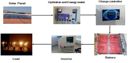
In these proposed system, Solar panel is connected to the optimizer. The optimizer is used to change the connection or switch based on climate condition. When there is no radiation from the sun at that time supply is taken from EB. Optimizer is connected to the charge controller; it controls the supply voltage of the battery. Battery can used to store the energy
during low load condition and stored can be utilized during high load demand [14].
[image:2.595.327.551.157.268.2]The arrangement of proposed solar system with charge controller is shown in figure 1.
Fig- 1: Arrangement of proposed system
The proposed solar system consists of following components. Such as,
1. Solar Panel
2. Charge Controller
3. Optimizer
4. Inverter
5. Battery
6. Load
Solar Panel convert sun light energy (Radiation) into useful electrical energy. Charge controller maintains constant input voltage supply to the battery. Optimizer function is If the current from solar panel, it can be varied by the climate condition. So, the working condition of the solar panel is to optimize the current both EB and solar supply.
The Inverter covert given DC supply in to AC supply. Battery it is used to store the energy from solar panel. Load is device it consumes electrical supply from source and it convert into some useful work (Light, heat, Illuminations, etc.,). In this proposed work inductive (Incandescent lamp) load is considered for analysis [15].
3.Maximum power point tracking
Maximum power point tracking is a technique commonly used with wind turbines and PV solar systems to maximize power extraction under all conditions. Although solar power is mainly covered, the principle applies generally to sources with variable power. PV solar systems exist in many different configurations with regard to their relationship to inverter systems, external grids, battery banks, or other electrical loads [2-5].
3.1 Block diagram of MPPT
© 2018, IRJET | Impact Factor value: 6.171 | ISO 9001:2008 Certified Journal | Page 3578 The output of converter is connected to load and output
voltage is controlled by commend signal received from the MPPT through DAC (Digital to Analog Convertor) [10]. In this work incandescent lamp is considered as a load for analysis.
[image:3.595.304.566.117.357.2]The block diagram of MPPT is shown in figure 2. It comprises solar panel, DC-DC convertor, DAC, MPPT and load.
Fig- 2: Block diagram of MPPT controller
Regardless of the ultimate destination of the solar power, though, the central problem addressed by MPPT is that the efficiency of power transfer from the solar cell depends on both the amount of sunlight (Radiation) falling on the solar panels and the electrical characteristics of the load. As the amount of sunlight varies, the load characteristic that gives the highest power transfer efficiency changes, so that the efficiency of the system is optimized when the load characteristic changes to keep the power transfer at highest efficiency [7].
There are number of maximum power point tracking (MPPT) methods available to operate the PV system at maximum power point. The proposed system has used Perturb & Observe (P&O) MPPT algorithm for the design and implementation [8].
When irradiance and temperature are constant or slowly varying, the P&O method tracks MPP steadily and calculate the operating point at which the battery is capable of producing maximum power. In this method, the controller provides the PWM signal to adjust the voltage, adjustment is done by Buck converter and measures power, if the power increases, further adjustments in that direction are tried until power no longer increases. At climatic condition are poor at the controller stored in voltage it gives to the battery in constant value. The value can be used to boost from buck boost controller, at that controller voltage value can increased or boost up from PV module to the controller [9].
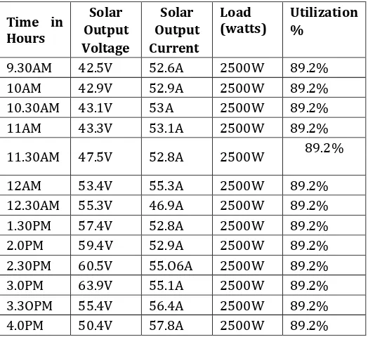
4.Result analysis
The system analysis is made by comparing the amount of energy utilized during the day time. The energy observed during various time schedules and energy calculations are tabulated and shown in Table 1.
TABLEI:COMPARISONOFSOLARPANELOUTPUTWITH DIFFERENT TIME PERIOD
Time in Hours
Solar Output Voltage
Solar Output Current
Load
(watts) Utilization %
9.30AM 42.5V 52.6A 2500W 89.2%
10AM 42.9V 52.9A 2500W 89.2%
10.30AM 43.1V 53A 2500W 89.2%
11AM 43.3V 53.1A 2500W 89.2%
11.30AM 47.5V 52.8A 2500W 89.2%
12AM 53.4V 55.3A 2500W 89.2%
12.30AM 55.3V 46.9A 2500W 89.2%
1.30PM 57.4V 52.8A 2500W 89.2%
2.0PM 59.4V 52.9A 2500W 89.2%
2.30PM 60.5V 55.O6A 2500W 89.2%
3.0PM 63.9V 55.1A 2500W 89.2%
3.3OPM 55.4V 56.4A 2500W 89.2%
4.0PM 50.4V 57.8A 2500W 89.2%
TABLE II: COMPARISON OF SOLAR RADIATION OUTPUT WITH DIFFERENT TIME PERIOD
Time
Radiatio n (Btu)
Radiation in watt
Max(w/m2
)
Radiation in watt
Min(w/m2
)
Temperatur e 0c
9.30 am 300 1140 897 27
10.00
am 300 1140 897 27
10.30
am 335 1085 995 27
11.00
am 340 1026 989 30
11.30
am 360 1147 1143 32
12.00
am 365 1165 1154 32
12.30
pm 384 1216 1214 33
1.00 pm 370 1150 1142 32
1.30 pm 340 1081 1076 31
2.00 pm 325 1028 1026 31
2.30 pm 308 986 973 27
3.00 pm 285 906 901 26
3.30 pm 280 900 890 26
4.00 pm 277 870 862 25
[image:3.595.51.281.175.310.2]© 2018, IRJET | Impact Factor value: 6.171 | ISO 9001:2008 Certified Journal | Page 3579 As seen from the Table I and II it is clearly observed that
during the morning time maximum power is obtained as
1140 w/m2 and the minimum power is obtained as 895 w/m2
from the solar panel with the atmospheric temperature of 380c.
In the evening the maximum and minimum value of power is noted as 850 w/m2 and 845 w/m2 respectively with the atmospheric temperature of 250 c.
5.CONCLUSIONS
Solar power is a renewable energy source and it is emitted by sun. The main issue in solar panel is output voltage of panel is varied with respect to time because of radiation. By using MPPT technique-based charge controller the input voltage given to battery is regulated as constant input voltage. The maximum power point tracking technique-based controller is clubbed with electrical.
The performance of proposed MPPT technique-based controller performance is verified during different radiations of sunlight during day time with different time interval. And also, the performance is verified by connecting incandescent lamp as load. It is clearly evident that proposed MPPT technique-based controller improve the utilization of solar power during different time period within the day time.
REFERENCES
[1] De Brito, M.A.G., Galotto, L., Sampaio, L.P., e Melo, G.D.A.
and Canesin, C.A., 2013. Evaluation of the main MPPT
techniques for photovoltaic applications. IEEE
transactions on industrial electronics, 60(3), pp.1156-1167.
[2] Srivastava, M., Agarwal, S. and Sharma, E., 2015. Design
and Simulation of Perturb and Observe MPPT Algorithm for 72 Cell Solar PV System. International Journal of Soft Computing and Engineering (IJSCE), ISSN, 4(5), pp.2231-2307.
[3] Liu, Y.H., Leou, R.C. and Cheng, J.S., 2005, June. Design
and implementation of a maximum power point tracking battery charging system for photovoltaic applications. In Power Tech, 2005 IEEE Russia (pp. 1-5). IEEE.
[4] Prasad, S.Y., Chhetri, B.B., Adhikary, B. and Bista, D.,
2010, September. Microcontroller based intelligent DC/DC converter to track Maximum Power Point for solar photovoltaic module. In Innovative Technologies for an Efficient and Reliable Electricity Supply (CITRES), 2010 IEEE Conference on (pp. 94-101). IEEE.
[5] Sivagamasundari, M.S., Mary, P.M. and Velvizhi, V.K.,
2013. Maximum power point tracking for photovoltaic system by perturb and observe method using buck boost converter. International Journal of Advanced Research
in Electrical, Electronics and Instrumentation Engineering, 2(6), pp.2433-2439.
[6] Hohm, D.P. and Ropp, M.E., 2003. Comparative study of
maximum power point tracking algorithms. Progress in photovoltaics: Research and Applications, 11(1), pp.47-62.
[7] Villalva, M.G., Gazoli, J.R. and Ruppert Filho, E., 2009,
September. Analysis and simulationof the P&O MPPT algorithm using alinearized PV array model. In Power Electronics Conference, 2009. COBEP'09. Brazilian (pp. 189-195). IEEE.
[8] Elgendy, M.A., Zahawi, B. and Atkinson, D.J., 2012.
Assessment of perturb and observe MPPT algorithm implementation techniques for PV pumping
applications. IEEE transactions on sustainable
energy, 3(1), pp.21-33.
[9] Esram, T. and Chapman, P.L., 2007. Comparison of
photovoltaic array maximum power point tracking
techniques. IEEE Transactions on energy
conversion, 22(2), pp.439-449.
[10] De Brito, M.A., Junior, L.G., Sampaio, L.P., e Melo, G.A. and
Canesin, C.A., 2011, September. Main maximum power point tracking strategies intended for photovoltaics. In Power Electronics Conference (COBEP), 2011 Brazilian (pp. 524-530). IEEE.
[11] Theraja, B.L. and Theraja, A.K., 2006. A textbook of
Electrical Technology in SI Units. S. Chand and Co, 2, pp.1115-1242.
[12] Haruni, A.O., Negnevitsky, M., Haque, M.E. and Gargoom,
A., 2013. A novel operation and control strategy for a standalone hybrid renewable power system. IEEE transactions on sustainable energy, 4(2), pp.402-413.
[13] Prasad, S.H., Kariyappa, B.S., Nagaraj, R. and Thakur, S.K.,
2009. Micro Controller Based Ac Power
Controller. Wireless Sensor Network, 1(02), p.76.
[14] Cowlishaw, M.F., 1974. The characteristics and use of
lead-acid cap lamps. PDF). Trans. British Cave Research Association, 1(4), pp.199-214.
[15] Othman, R., Basirun, W.J., Yahaya, A.H. and Arof, A.K.,
2001. Hydroponics gel as a new electrolyte gelling agent for alkaline zinc–air cells. Journal of power sources, 103(1), pp.34-41.
[16] Hamid, M.R., Rahimi, J., Chowdhury, S. and
© 2018, IRJET | Impact Factor value: 6.171 | ISO 9001:2008 Certified Journal | Page 3580 BIOGRAPHIES
K. Gobinath, was born on July 20,1996, currently graduate student in the electrical engineering department, Paavai Engineering College, Namakkal, tamilnadu, India. His area of interest includes Control System and Electrical Machines.
S. Muthukrishnan, was born on February 18,1997,currently graduate student in the electrical engineering
department, Paavai Engineering
College, Namakkal, tamilnadu, India. His area of interest includes Power Plant Engineering.
S.Rajasekar , was born on May 19,1997, currently graduate student in the electrical engineering department, Paavai Engineering College, Namakkal, tamilnadu, India. His area of interest includes Circuit Theory.
R.Rajmohan , was born on March 26,1997, currently graduate student in the electrical engineering department, Paavai Engineering College, Namakkal, tamilnadu, India. His area of interest includes Digital Logic Circuit.
K.Jagatheesan received his B.E degree in electrical engineering in Hindusthan College of Engg & Technology, Coimbatore, Tamil Nadu, and M.E. degree in Applied Electronics in from
Paavai College of Engineering,
Namakkal, Tamil Nadu, . Now, he is currently working towards the Ph.D. degree with the faculty of Information
& Communication Engg, Anna