© 2018, IRJET | Impact Factor value: 6.171 | ISO 9001:2008 Certified Journal | Page 2376
CFD Analysis of vortex breakdown on double delta wing
Gokul Suresh
1, Gokul Vijayakumar
2, Rosch Roosevelt
3, Jacob Kurian
4, Dr. Jeoju M Issac
51,2,3,4 Department of Mechanical Engineering, Mar Athanasius College of Engineering, Kerala, India
5Professor, Department of Mechanical Engineering, Mar Athanasius College of Engineering, Kerala, India
---***---Abstract –
Most of the research and development efforts inthe field of aerodynamics are devoted to the study of flow phenomena over the aircraft wings. A relatively new tool in the exploration of this flow regime is Computational Fluid Dynamics (CFD). The present study consist of numerical simulation of flow field over a double delta wing using CFD. The wing model has a sharp leading edge and 76/40° configuration which is the representation of the current fighter aircraft. The major objective of the study is to observe the effect of Angle Of Attack and Mach number on vortex flow structure and pressure. In this study we are varying the angle of attack from 10º to 25º and for each angle of attack we are
considering three Mach numbers (0.4, 0.85, 1.4) representing subsonic, transonic and supersonic conditions.
Key Words: CFD, Double Delta Wing, Vortex flow
1. INTRODUCTION
Delta wing are widely used in a great number of supersonic aircraft wings like Boeing X-32, Dassault Rafale, Lockheed A-12 etc. Pure delta wings suffer from some undesirable characteristics, notably flow separation at high angles of attack and high drag at low speeds. This originally limited them primarily to high-speed, high-altitude interceptor roles. Since then the delta design has been modified in different ways to overcome some of these problems. One such modified form of delta wing is double delta wing. Delta wings are having high aerodynamic characteristics than conventional wings due to the vortex dominated flow field. Nowadays, CFD is considered to an important alternative to the classical wind tunnel experiments and plays an important role in modern aircraft design and development.
1.1 Numerical modelling
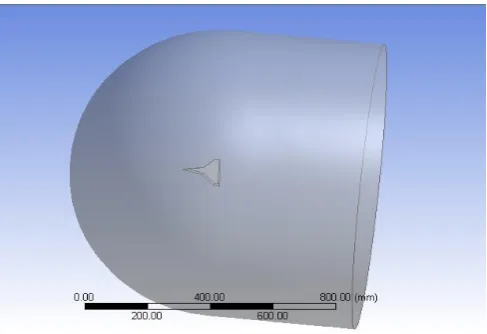
[image:1.595.313.557.179.346.2]The double delta wing is designed in CATIA V5 and simulated in ANSYS Fluent with density based solver and SST k-ԝ to account for boundary layer interactions. The double delta wing is designed in CATIA V5, which is a parametric based CAD software used to design variety of complex model with minimum possibility of error. After designing the model in CATIA, the model is exported into ANSYS Design Modeler to create fluid domain around that delta wing. For fluid domain we have considered approximately three times the chord length of double delta wing in order to observe the characteristics over the body.
Fig-1: Fluid domain over a double delta wing
1.2 Methodology
In this project we need to mesh the domain such that near the delta wing we have to create inflation layer and fine mesh in order to get the accurate results and far away from the delta wing coarse mesh in order to reduce the number of elements.We have run the simulation in Fluent 15.0 which is a robust computational fluid dynamics tool used to compute complex problems like shock diamonds and boundary layer interactions in high speed compressible flows. The necessary model and boundary condition are stated in pre-processor. The solver method is specified in solver setting and results are taken from the CFD post-processor. Since our flow is compressible flow, we are considering density based solver which will give better results than pressure based solvers.
[image:1.595.313.557.572.741.2]International Research Journal of Engineering and Technology (IRJET) e-ISSN: 2395-0056
Volume: 05 Issue: 03 | Mar-2018 www.irjet.net p-ISSN: 2395-0072© 2018, IRJET | Impact Factor value: 6.171 | ISO 9001:2008 Certified Journal | Page 2377
2. RESULT AND DISCUSSIONS
CASE 1: Angle of attack is 10º
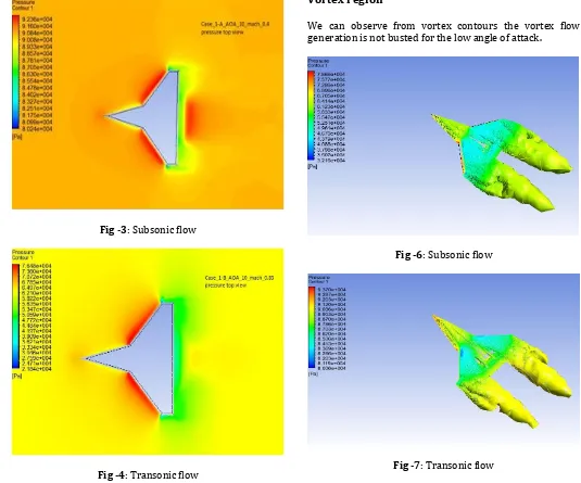
Pressure variations
[image:2.595.309.562.81.262.2]Pressure is the one of the main parameter which will produce the required lift for the aircraft. As the angle of attack increases the pressure will be high at bottom and it will be lesser in top surface. Due to the pressure difference between the two surfaces the flow will swirl from the bottom to top surface and this flow movement will cause the body to lift. In this case we are comparing the pressure variation with angle of attack 10º and for three different Mach numbers. As the Mach number increases from subsonic to supersonic (0.4, 0.85, 1.4) the pressure will decrease as per the pressure contour are shown below.
Fig -3: Subsonic flow
Fig -4: Transonic flow
Fig -5: Supersonic flow
Vortex region
[image:2.595.25.560.305.750.2]We can observe from vortex contours the vortex flow generation is not busted for the low angle of attack.
Fig -6: Subsonic flow
[image:2.595.311.558.357.519.2]© 2018, IRJET | Impact Factor value: 6.171 | ISO 9001:2008 Certified Journal | Page 2378 Fig -8: Supersonic flow
Two spiral vortices are formed at both sides of the double delta wing. This vortices will significantly contribute to the lift generated by the wing.
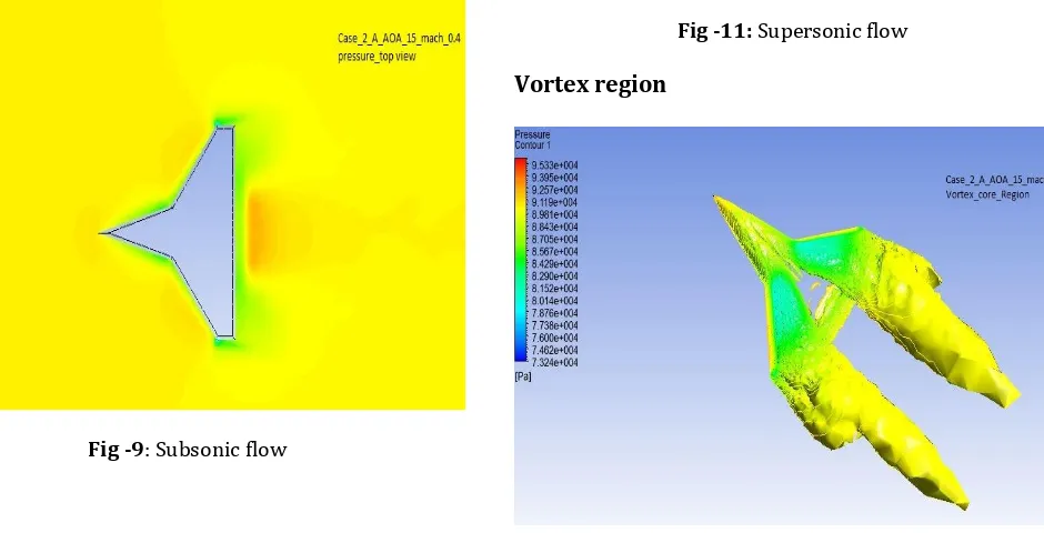
CASE 2: Angle of attack is 15º
Pressure variations
We can observe that with increase in angle of attack the pressure values are decreasing. The variations of pressure contour for an angle of attack of 15º under subsonic, transonic and supersonic conditions are shown in the plots below.
[image:3.595.53.557.34.275.2]Fig -9: Subsonic flow
[image:3.595.77.547.484.724.2]Fig -10: Transonic flow
Fig -11: Supersonic flow
Vortex region
International Research Journal of Engineering and Technology (IRJET) e-ISSN: 2395-0056
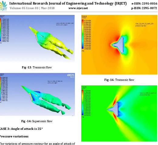
Volume: 05 Issue: 03 | Mar-2018 www.irjet.net p-ISSN: 2395-0072 [image:4.595.40.561.32.509.2]© 2018, IRJET | Impact Factor value: 6.171 | ISO 9001:2008 Certified Journal | Page 2379 Fig -13: Transonic flow
Fig -14: Supersonic flow
CASE 3: Angle of attack is 25º
Pressure variations
The variations of pressure contour for an angle of attack of 25º under subsonic, transonic and supersonic conditions are shown in the plots below. With the increase in angle of attack the pressure is found to be reducing.
Fig -15: Subsonic flow
Fig -16: Transonic flow
Fig -17: Supersonic flow
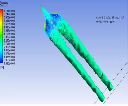
[image:4.595.40.559.556.741.2]Vortex region
© 2018, IRJET | Impact Factor value: 6.171 | ISO 9001:2008 Certified Journal | Page 2380 Fig -19: Transonic flow
Fig -20: Supersonic flow
The pressure of vortices are found to be decreasing with increasing angle of attack. As the pressure reduces the vortices strength increases.
Streamlines
[image:5.595.35.560.50.493.2]Stream lines are used to define how the flow is around the delta wing and will give the vortices path over the body. As angle of attack and Mach number increases the vortices are coiled-up at the tip. The stream lines of the supersonic flow regime in all the three cases angle of attack are plotted to observe the vortices. This coiling-up of the vortices can be observed from the streamlines as plotted below.
Fig -21: Angle of attack = 10º
Fig -22: Angle of attack = 15º
[image:5.595.305.559.300.496.2] [image:5.595.36.287.311.518.2] [image:5.595.307.561.530.707.2]International Research Journal of Engineering and Technology (IRJET) e-ISSN: 2395-0056
Volume: 05 Issue: 03 | Mar-2018 www.irjet.net p-ISSN: 2395-0072© 2018, IRJET | Impact Factor value: 6.171 | ISO 9001:2008 Certified Journal | Page 2381
3. CONCLUSIONS
As angle of attack increases the strength of the vortex is increasing and soon they burst from the wing surface. At higher angle of attack, the vortex bursting point moves upstream towards the apex (leading edge).The vortices will significantly improve the lift generated by the delta wing.
Pressure values are decreasing with increase in angle of attack and Mach number. As angle of attack increases, the lift and drag values increases. Hence the lift to drag ratio will increase and the strake vortex induces the strong outflow, which will energize the boundary layer on the upper surface of the wing and keeps it attached to upper surface for higher angle of attack than the delta wing without strake. Hence it can be concluded that the aerodynamic characteristics of a double delta wing are far better than that of a pure delta wing.
ACKNOWLEDGEMENT
We express our sincere gratitude and thanks to our esteemedguide Dr. Jeoju M Issac , professor, department of mechanical engineering , Mar Athanasius college of engineering for his valuable guidance and support. The authors would also like to thank the Department of mechanical engineering of Mar Athanasius college of Engineering for their interesting and fruitful discussions during the production of this work.
REFERENCES
[1] Kazuhisa Chiba and Shigeru Obayashi “CFD
visualization of primary vortex structure on a 65- degree delta wing” 42nd AIAA meeting ,8 January 2004
[2] L.A Schiavetta ,O.J Boelens,S.Crippa ,R.M Cummings,
W.Fritz, ”shock effects on delta wing vortex breakdown”,vol.46,3,may-june 2009
[3] X.Zhang,Z.Wang and I.Gurusul,”control of multiple
vortices over a double delta wing”,5-9June 2017,47th AIAA fluid dynamics conference