Based on Image Processing
Hilal Al-Kharusi, Ibrahim Al-BahadlySchool of Engineering and Advanced Technology, Massey University, Palmerston North, New Zealand Email: [email protected], [email protected]
Received 2 March 2014; revised 6 April 2014; accepted 14 April 2014
Copyright © 2014 by authors and Scientific Research Publishing Inc.
This work is licensed under the Creative Commons Attribution International License (CC BY).
http://creativecommons.org/licenses/by/4.0/
Abstract
This paper aims to present an intelligent system for parking space detection based on image pro- cessing technique. The proposed system captures and processes the rounded image drawn at parking lot and produces the information of the empty car parking spaces. In this work, a camera is used as a sensor to take photos to show the occupancy of car parks. The reason why a camera is used is because with an image it can detect the presence of many cars at once. Also, the camera can be easily moved to detect different car parking lots. By having this image, the particular car parks vacant can be known and then the processed information was used to guide a driver to an availa-ble car park rather than wasting time to find one. The proposed system has been developed in both software and hardware platform. An automatic parking system is used to make the whole process of parking cars more efficient and less complex for both drivers and administrators.
Keywords
Intelligent Parking, Image Processing, Space Detection
1. Introduction
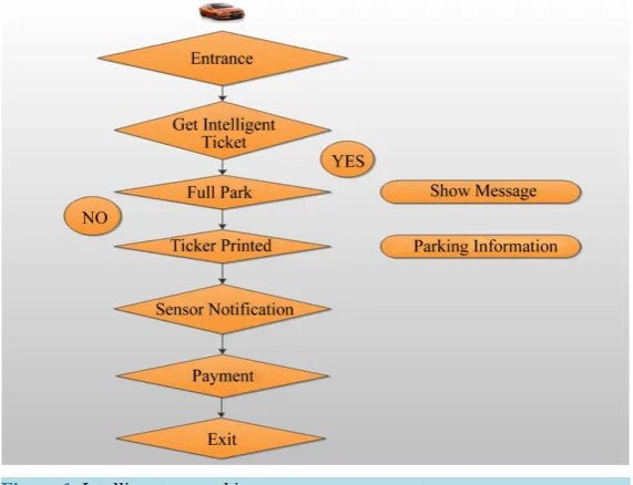
Figure 1. Intelligent car parking system management.
There are numerous methods of detecting cars in a car park such as Magnetic sensors, Microwave Radar, Ul- trasonic sensors and image processing [1] [2]. This project discusses image processing. This is used because cameras can capture many cars at once making them efficient and inexpensive [3]-[6]. One or more cameras are used for video image processing. Software is needed to process the images taken by the cameras. This processing is usually done by examining the difference between consecutive video frames [7]. The area that a camera scans can be easily changed. There are two ways of using this system either by applying the edge detec-tion with boundaries condidetec-tion method for image detecdetec-tion module or applying point detecdetec-tion with canny oper-ator method. In this project, the parking lot detection is done by identifying the green rounded image drawn at each parking lot. Matlab is used as a software platform [8]-[11]. Two types of car parks photos will be used. First one will be taken from Google earth and other one is a real photo for the car park.
2. System Module
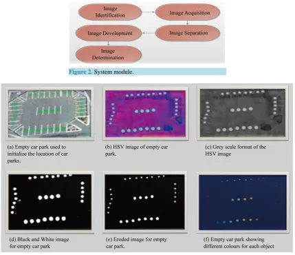
One or more cameras are used for video image processing .Software is needed to process the images taken by the cameras.The video image technique has five modules for this type of photos [12]. The whole process is shown inFigure 2.
The following will explain in detail each module.
2.1. Image Identification
First an image of the car park could be taken when there are no cars in the car park as in Figure 3(a). This would be used for the system to record the location of all the car parks. The RGB value can be used to find where green circles are that represent empty car spaces. With these the system will know where to look for cars in the future [13]. For the empty car park, to get the location of the green dots, the image is converted into an HSV image as is shown in Figure 3(b).This is done through using the rgb2hsv command in Matlab.
The HSV image in Figure 3(c) is simplified to a black and white binary image so that it is easier to deal with by making the pixels white where the threshold is more than 40%. In order to do this the HSV image needs to be converted to a gray scale format so that each pixel can be easily can compared with the threshold as it is shown in Figure 3(d). The equation to do this is shown in Equation (1). The rgb2gray command is used to do this.
Figure 2. System module.
Figure 3. Image identification.
means if the pixel is less than the threshold the colour of it will be black. Otherwise it will be white as it is shown in Figure 3(d). As can be seen in Figure 3(e); there are some small white parts of the image. These can be removed by using the erode function as it is shown in Figure 3(f). The imerode command is used to remove the small dots in the image. The object used to erode the image was created through using the following com-mand: se3 = strel(‘disk’, 3).
This creates a disc with a radius of three that is used by the erode function. The result of using this function is shown in Figure 3(f). The following code shows how this is done:
if (newmatrix(y,x) > 0) % an object is there, if (e(newmatrix(y,x)) = 0) this object has not been seen e(newmatrix(y,x)) = x; make the value and index 3 equal to the current X coordinate.
2.2. Image Acquisition
A camera placed at a fixed position above the cars will be used to acquire the image used to calculate the va-cancy of the car parks. This camera should be in a position where can clearly see all the car parks and not be ob-structed by any objects. Figure 4 shows an example of what an image may look like.
2.3. Image Separation
Figure 4. Car Park with green dots for car park spaces.
Figure 5. Three dimensional graphs of samples of RGB values from four images.
which means they could be easily distinguished from other objects. These represent the green dots. These dots are all are high in green and low in blue.
A cube could be made that encompasses only these dots. Then, if the average colour of an object is within this cube, it could be said that it is a green dot.
A simpler method of finding the green dots was found as explained in the previous section. This involved us-ing the HSV image of the car park.
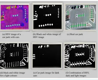
As it can be seen in Figure 6(a), the empty car parks are still very bright compared with other objects. This image was converted to a grey image and then to a black and white image (see Figure 6(b)) by using the same 40% threshold mentioned in initialization section.
To avoid getting the surface of the car park, which is grey, the bright and dark colours are obtained (see
Figure 6(c) and Figure 6(d)). To detect light colours such as white (to get white cars and white road markings) a high threshold of 70% as used to form a black and white image as shown in Figure 6(e). In order to see all the objects the three black and white images are combined.
This is done by using the OR functions as shown in the code below (where “|” is the OR operator): Mix = HSVBWObject | lightObject | DarkObject;
Figure 6. Image separation.
2.4. Image Development
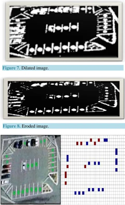
After obtaining the segments for the objects used the noise in the image needs to be removed. This can be done through dilation and erosion. Dilation increases the boundary of the objects in the image. This causes a problem in this image as shown in Figure 7. The problem is that objects merge together so it is hard to distinguish object from one another. However this is good to fill up holes in objects.
Erosion decreases the boundary of the objects so that they can be easily distinguished from one another. Figure 8 demonstrates the usefulness of this function. After erosion objects are more distinguishable from each other and small dots are removed. This prepares the image to identify whether parks are empty or filled.
2.5. Image Determination
By using the coordinates found in the initialization of the car park, each car park slot can be analysed to deter-mine whether a car is there or not. There were three methods used to deterdeter-mine whether car parks were full or not. If the height, width or size of the connected object at the car park coordinates were either too big or too small then the object was considered to be a car. In this case the car park was given the value 5 meaning it is occupied. This information was displayed as shown in Figure 9.
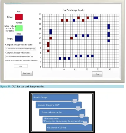
The GUI used to run the Matlab program that opens the image and produces an output as is shown in Figure 10.
3. Case Study for the Whole Process
This part describes the process of determining the presence of cars at car spots from a camera image at large car park. There are two different methods of implementing this system: either applying point detection with canny operator method or applying the edge detection with boundaries condition method for image detection module. It is an indispensable for detecting a car in the car park is to prepare a template image and edge Image. The aim of this project is to detect the existence of any car in each park slot.
3.1. Process of Template Images
Figure 7. Dilated image.
Figure 8. Eroded image.
Figure 9. Comparison between the RGB image and the output produced from the HSV image.
paring a template Image technique has five steps [15] as they are shown in Figure 11. 3.1.1. Acquire Image
First an image of the car park could be taken when there are no cars in the car park as is shown in Figure 12(a). This would be used for the system to record the location of all the car parks. The RGB value can be used to find where green circles are that represent empty car spaces. With these the system will know where to look for cars in the future.
3.1.2. Convert Image to HSV
For the empty car park, to get the location of the green dots, the image is converted into an HSV image as is shown in Figure 12(b). This is done through using the “rgb2hsv” command in Matlab.
3.1.3. Extraction and Detection
Figure 10. GUI for car park image reader.
Figure 11. Processing steps of template image.
3.1.4. Red Pixels and Noise Elimination
First of all the red segment of the image is extracted because as we know, red pixels are most power full seg-ment of the image as it is shown in Figure 12(c). If there are objects in the environment that have the same val-ue of red pixels that will be displayed in the extracted image as well. This will be noise for the extracted image and may create an inaccurate result to be obtained when using the Hough Transform. Therefore, parts that do not match the shape of the dot or circle that is being looked at should be trimmed away.
The process of circle detection is shown in the following points:
• Create a accumulator space relative to the pixels and set these values to the zero • For each edge, increment all values according to the circle equation
(
) (
2)
2 2i−a + −j b =r (2)
Figure 12. Whole process of template image.
• This will give the variable “a” in the equation
• Now for all possible values of “a” find the values of “b” which satisfy the equation • Search for local maxima. These are the points which have higher probability then others • These maxima are the location of the circles
• Draw a circle using rect command in Matlab to obtain Figure 12(d)
3.2. The Process of Edge Image
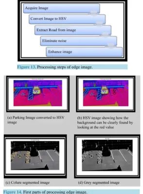
There are many ways to differentiate different objects and extract them but all the processes have their limita-tions. A process considered here is back ground eliminalimita-tions. As many car parks have same road which here is defined as its background. The background can be extracted and hence the object like cars can easily be detected. The processing of edge image technique has five steps [16] as they are shown in Figure 13.
3.2.1. Converting to HSV
First the image is converted to HSV because it is easy to differentiate different coloured pixels in HSV space. In
Figure 13(a) it can be clearly seen that the red looking colors are back ground. By looking at the pixels in the
Figure 13(b) it becomes clear that pixels for the background fall within a specified range of colours. By execut-ing the followexecut-ing code, the background can be obtained.hue = (Img_HSV(:,:,1) >= 0) & (Img_HSV(:,:,1) <= 0.9); saturation = (Img_HSV(:,:,2) >= 0.01) & (Img_HSV(:,:,2).
The object is eliminated as it is shown in Figure 13(c) and then it is converted to a grey image as it is shown in Figure 14(d).
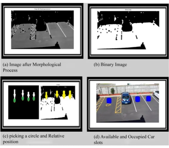
3.2.2. Morphological Processing
This is non-linear process which is related to shape and morphology of image. It is relative to ordering of pixel value not their numerical values as it is shown in theFigure 15(a).
Figure 13. Processing steps of edge image.
Figure 14. First parts of processing edge image.
image contains white space then the parking lot is empty if it contains black pixel then the space is occupied as it is shown in Figure 15(d).
4. Communication
In order to transfer the image to the computer, a wireless system is used. This is composed of a video camera that captures the image, a transmitter sends the images to the receiver in the control room, the receiver will send signals to a computer. The computer will process the signals and send them to the indoor transmitter. The com-puter has a FPGA platform attached that creates a filter to filter out the noise in the image. The indoor transmit-ter sends the signals wirelessly to the receiver attached with the monitor or display [17] [18] as shown in Figure 16.
5. Architecture and Components
Figure 15. Reaming parts of processing edge image.
Figure 16. Process of transferring images to the computer.
6. Power Sources
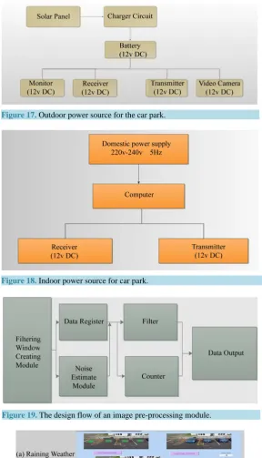
The lifetime of the video camera, transmitter, receiver, PC and the monitor depends on the power source. In this project a solar panel is used as an outdoor power source. It supplies the power to the transmitter, receiver and monitor through a 12v DC battery [22]-[24]. A whole process of Outdoor power source for the car park is shown in Figure 17.
Also a domestic power supply is used as an indoor power source. It supplies the power to the computer transmitter and receiver [25] [26]. A whole process of indoor power sources is shown in Figure 18.
7. Image Pre-Processing Module
An Image pre-processing module is mostly about the design of filter. It is achieved in the FPGA [27]. The whole design is shown in Figure 19. A filtering window creating module creates filtering windows that are required by the use of follow-up modules. The noise estimate module estimates the type of noise, so that the best kind of fil-tering approach can be decided [28] [29]. It counts the rows and columns of the input data to determine whether the window can be legitimately done by the counter’s function and then to count the lawful window data to determine the output data in an image location. The last image data are sent to the next level of processing equipment [30].
8. Car Park Display
[image:10.595.201.427.350.449.2]Figure 17. Outdoor power source for the car park.
[image:11.595.187.446.550.705.2]Figure 18. Indoor power source for car park.
Figure 19. The design flow of an image pre-processing module.
vacant or filled. The current limitation in this paper is the weather conditions and it can be improved by filtering the image in a high quality transform, so the camera can detect the park lots in any weather condition.
References
[1] Yu, H.M., Pang, Z. F. and Ruan, D.R. (2008) The Design of the Embedded Wireless Vehicles Monitoring Management System Based on GPRS : Evidence from China. International conference on Intelligent Information Technolo-gy,Shanghai, 21-22 December 2008, 677-680.
[2] Wang, L.F., Chen, H. and Li, Y. (2009) Integrating Mobile Agent with Multi-agent System for Intelligent Parking Ne-gotiation and Guidance. 4th IEEE Conference on Industrial Electronics and Applications, 25-27 May 2009, Xi’an, 1704-1707.
[3] Abdallah, L., Stratigopoulos, H.-G., Mir, S. and Kelma, C. (2012) Experiences With Non-Intrusive Sensors For RF Built-In Test. 2012 IEEE International Test Conference (ITC), Anaheim,5-8 November 2012, 1-8.
[4] D. Kim and W. Chung (2008) Motion Planning for Car-Parking Using the Slice Projection Technique. IEEE/RSJ In-ternational Conference on Intelligent Robots and Systems, Nice,22-26 September 2008, 1050-1055.
[5] Zhang, B., Jiang, D.L., Wang, F. and Wan, T.T. (2009) A Design of Parking Space Detector Based on Video Image.
The Ninth International Conference on Electronic Measurement & Instruments, Beijing, 16-19 August 2009, 253-256. [6] Sreedevi, A.P. and Nair, B.S.S. (2011) Image Processing Based Real Time Vehicle Theft Detection and Prevention
System. 2011 International Conference on Process Automation, Control and Computing (PACC), Coimbatore, 20-22 July 2011, 1-6.
[7] Zhang, X., Li, Y., Wang, J. and Chen, Y. (2009) Design Of High-Speed Image Processing System Based on FPGA.
The Ninth International Conference on Electronic Measurement & Instruments, Beijing, 16-19 August 2009, 65–69. [8] Jermsurawong J., Ahsan, M., et al. (2012) Car Parking Vacancy Detection and Its Application in 24-Hour Statistical
Analysis. 10th International Conference on Frontiers of Information Technology, Islamabad, 17-19 December 2012, 84-90,
[9] Lin, S., Chen, Y. and Liu, S. (2006) A Vision-Based Parking Lot Management System. IEEE International Conference on Systems, Man, and Cybernetics, Taipei, 8-11 October 2006, 2897-2902.
[10] Conci, A., Carvalho, J. and Rauber, T. (2009) A Complete System for Vehicle Plate Localization, Segmentation and Recognition in Real Life Scene. IEEE Latin America Transactions, 7, 497-506.
http://dx.doi.org/10.1109/TLA.2009.5361185
[11] Lee, K. (2012) Colour Matching for Soft Proofing Using a Camera. IET Image Processing, 6, 292-300.
[12] Tang, V., Zheng, Y., Cao, J., Hong, T. and Polytechnic, K. (2006) An Intelligent Car Park Management System Based on Wireless Sensor Networks. 1st International Symposium on Pervasive Computing and Applications, 3-5 August 2006, Urumqi, 65-70.
[13] Jinghong, D., Yaling, D. and Kun, L. (2007) Development of Image Processing System Based on DSP and FPGA. The Eighth International Conference on Electronic Measurement and Instruments, 16 August 2007-18 July 2007, Xi’an, 791-794.
[14] Matjašec, Ž. and Ĉonlagiü, D. (2011) An Optical Signal Processing Device for White-Light Interferometry, Based on CPLD. 2011 Proceedings of the 34th International Convention MIPRO, Opatija, 23-27 May 2011, 60-64.
[15] Wang, Y., Zhou, G. and Li, T. (2006) Design of a Wireless Sensor Network for Detecting Occupancy of Vehicle Berth in Car Park. Seventh International Conference on Parallel and Distributed Computing, Applications and Technologies, Taipei, December 2006, 115-118.
[16] Funck, S., Mohler, N. and Oertel, W. (2004) Determining Car-Park Occupancy from Single Images. 2004 IEEE Intel-ligent Vehicles Symposium, Parma, 14-17 June 2004, 325-328. http://dx.doi.org/10.1109/IVS.2004.1336403
[20] Yusnita, R., Norbaya, F. and Basharuddin, N. (2012) Intelligent Parking Space Detection System Based on Image Processing. International Journal of Innovation, Management and Technology, 3, 232-235.
[21] Caicedo, F. and Vargas, J. (2012) Access Control Systems and Reductions of Driver’s Wait Time at the Entrance of a Car Park. 7th IEEE Conference on Industrial Electronics and Applications (ICIEA), Singapore, 18-20 July 2012, 1639- 1644.
[22] Prasad, A.S.G., Sharath, U., Amith, B. and Supritha, B.R. (2012) Fiber Bragg Grating Sensor Instrumentation for Parking Space Occupancy Management. International Conference on Optical Engineering (ICOE), Belgaum, 26-28 July 2012, 1-4.
[23] Chien, S.A. (1994) Automated Synthesis of Image Processing Procedures for a Large-Scale Image Database. 4th In-ternational Conference on Knowledge and Smart Technology (KST), Austin, 13-16 November 1994, 796-800.
[24] Caicedo, F. and Vargas, J. (2012) Access Control Systems and Reductions of Driver’s Wait Time at the Entrance of a Car Park. IEEE 7th International Conference on Industrial Electronics and Applications, Singapore, 18-20 July 2012, 1639-1644.
[25] Boluk, P.S.,Irgan, K., Baydere, S. and Harmanci, E. (2011) IQAR : Image Quality Aware Routing for Wireless Mul-timedia Sensor Networks. 7th International Wireless Communications and Mobile Computing Conference (IWCMC), Istanbul, 4-8 July 2011, 394-399.
[26] Gall, R., Troester, F. and Mogan, G. (2010) Building an Experimental Car Like Mobail Robot for Fully Autonomous Parking. 2010 IEEE/ASME International Conference on Advanced Intelligent Mechatronics (AIM), Montreal, 6-9 July 2010, Montreal, 6-9 July 2010, 1081-1086. http://dx.doi.org/10.1109/AIM.2010.5695903
[27] Chen, M.K., Hu, C. and Chang, T.H. (2010) The Research on Optimal Parking Space Choice Model in Parking Lots. 3rd International Conference on Computer Research and Development (ICCRD), Shanghai, 11-13 March 2011, 93-97. [28] Barton, J., Buckley, J., O’Flynn, B., O’Mathuna, S.C., Benson, J.P., O’Donovan, T., Roedig, U. and Sreenan, C. (2007)
The D-Systems Project—Wireless Sensor Networks for Car-Park Management. IEEE 65th Vehicular Technology Conference, Dublin, 22-25 April 2007, 170-173.
[29] Souissi, R., Cheikhrouhou, O., Kammoun, I. and Abid, M. (2011) A Parking Management System Using Wireless Sensor Networks. 2011 International Conference on Microelectronics (ICM), Hammamet, 19-22 December 2011, 1-7. [30] Srikanth, S.V., Pramod, P.J., Dileep, K.P., Tapas, S., Patil, M.U. and Sarat, C.B.N. (2009) Design and Implementation
of a prototype Smart PARKing (SPARK) System Using Wireless Sensor Networks. International Conference on Ad-vanced Information Networking and Applications Workshops, Bradford, 26-29 May 2009, 401-406.