STREAMING BIREFRINGENCE STUDY OF THE INTERACTIONS OF SUBMICROSCOPIC PARTICLES
Thesis by Marcos lntaglietta
In Partial Ful£Ulment of the Requirements For the Degree of
Doctor of Philosophy
California Institute o! Technology Pasadena. California
ACKNOWLEDGMENTS
The author wishes to thank Professor J. Harold Wayland for suggesting the research, directing it. and offering much helpful ad-vice and encouragement.
Thanks are also due to Professor D. A. Morelli for helping in the design of the polarimeter, and to Dr. J. Vinograd for having con-ducted the ultracentrifuge teats and for having helped with many dis· cussions.
The author wishes to thank Dr. N.
s
.
Simmons of the Depart-ment and Laboratories of Nuclear Medicine and Radiation Biology of the University of Callfornia Medical Center at Los Angeles for having pro-vided the samplee of tobacco mosaic virus. He ts also indebted to P ro-fessor E. W. MerrUl of the School of Chemical Engineering of theMassachusetts Institute of Technology for making it possible to conduct the necessary viscosity measurements at his laboratory.
Thanks are due to the Applied Physics Corporation of Monrovia for having loaned the electronic equipment. Appreciation is eJ.."Presaed to Mr. P.
v
.
Knust-Graichen for having isolated the southern bean mo-saic virus and for having helped conduct the experiments, and to Mrs. Rol?erta Duffy for typing the manuecript.ABSTRACT
An apparatus for the observation of otrearning birefringence with photoelectric detection. in which the output signal nea.r the null is linear with respect to the angular distance to the null, was built and
tested. It was found that such an apparatus is able to establish the po• sition of the isocline with a.n accuracy of one degree for a relative retardation of 10·9.
The apparatus was subsequently used to study th.e streaming birefringence of tobacco mosaic virus and of mixtures of tobacco mo-saic virus and southern bean mosaic virus. Accurate measurements of the angle of isocline of both types of solutions showed that no sig-nificant difference exists between the experimental and theoretical results, once all the sources of extraneous birefringences are ac -counted for.
The amount of retardation of the mixtures was found to be lower than that for pure tobacco mosaic virus at equal concentrations of the ·latter and equal velocity gradients.
nus
experimental re~t isPART
L
u.
m.
IV.
TABLE OF CONTENTS TITLE
Acknowledgment
Abstract
Table of Contents INTRODUCTION
THEORY OF MEASUREMENT OF STREAMING BIREFRINGENCE
Z. 1 Optical System
2.. Z Sepazoadon of
Extraneous
Effects EXPERIMENTAL TECHNIQUE3. 1 Equipment
3.
ZAllgxunent
3. 3 Data HandlingEXPERIMENTAL RESULTS
PAGE
1
1
1
1824 2.4
2
9
3136
V. DISCUSSION OF EXPERIMENTAL RESULTS AND
CONCLUSIONS 51
APPENDIX A • Theoretical Derivatlcm of the SDR of a Solud.OG of Lcmg Slender Rods
A. 1 MotlOG o£ a Particle According to Hydrodynamic
63
Tbeory
64
A. Z Motlcm of the Particles Due to Brownian Mottoo
and Rotazy Dl£fustoo 78
A. 3 Dlstributlon Function 79
A.4 Optlc~Behanor 81
APPENDIX B • Sample Data
90
I. INTRODUCTION
The path oi a beam of light !n a transparent medium can be described through the use
oi Huygen's principle,
which states that each element oi a wave front may be regarded as the center of a secondarydisturbance which gives rise to wavelets. These wavelets propagate with a velocity equal to the velocity of propagation of the wave. The position of the wave front at any later time is given by the envelope of all wavelets.
In the general case of an anisotropic medium, two sets of H'uy-gen's wavelets propagate from every wave .front. Substances having thi1 property are said to exhibit birefringence. When there is a direc-tion along which the velocity of propagation of the two sets of wavelets is equal, the substance is said to be uniaxial, and this dlrectlou le called the optic axis. In an uniaxial cry•tal there are two indices of refraction which characterize the two sets of. Huygen's wavelets, with maximum and minimum values in directions perpendicular to each other and to the optic
axis.
One set of wavelets ls spherical and its velocity o£ propa-gation ia characterized by an index of refraction n0 • The second sot is ellipsoidal and has a maximum index of refraction ne ln a direction perpendicular to the optic axis. The amount of birefringence ls defined as the dtfierence (n
0 - ne) between the two indices.
-2-x2
[image:6.563.114.548.18.660.2]SBR is usually studied in solutions contained in the gap between
two concentric cylinders, such that the rotation of either will cause
a
very nearly linear velocity gradient in laminar
flow,
characterized by:which makes the solution become birefringent. with the
amount
of bl·refringence increasing stea.dUy with the velocity gradient G • In this
flow
ccmfiguration (Figure 1 ), a given volume element will have thedi-rections of maximum and rninimun"l indices of refraction in the x 2x3
plane, where the smallest angle between the axis with the largest index
of refraction and the streamline is the angle of isocline X. The amount
of birefringence An for a given wavelength "- is obtained from the
relation:
An :a (n o - n ) e
=
...lJr
=
f(G) c;.1T-Lwhere
o
is the observed phase dliference between the two directionsin radians, and t is the length of the path through the streaming fluid.
At
small
gradients in laminar flow,x
has been observed to approach 45° and .6.n ls proportional to G • At higher gradients X decreases,while An increases deviating from proportionality with G •
The behavior of solutions of small, rigid, asymmetric particle&
le explained by analyzing the motion of a single particle. In the pres-ence o£ a linear velocity gradient in laminar
flow,
the particle is com-pelled to rotate with a non-uniform angular velocity, which makes itparticle might have a certain angular position. The coupling of the angular distribution with the optical anisotropy of a particle yields the two main optical directions in the fluid as the directions of larger and smaller angular density.
The phenomenon was first observed by Maxwell ( 1) in 1866, and reported in 1873 in a paper which also described a. concentric cylinder apparatus in which SBR could easily be produced.
Several theories have been proposed to explain the experimental evidence, the most successful at present being that of. Peterlin and Stu.a.rt(Z.). This theory assumes that a system of rigid, submicroscopic particles of ellipsoidal shape suspended in a medium becomes optically anisotropic when it is subjected to shear, due to the non-uniform motion of the particles. The theory has been extended to non-rigid particles, to the presence of heterogeneous populations, and to the superimposition of magnetic and electric fields.
The techniques of SBR were found to be applicable to the study of fiow patterns in two-dimensional flow fields, and to the characterization of macromolecules. In the latter field, useful information from sub-microscopic particles in solution can be obtained by relating the size, shape, mass, and dlsperslty of the particles to the optical properties of the system. Particularly eigniflcant le the data that can be obtained by extrapolation to zero shear, a method by which the rotary diffusion constant can be determined, as well a.s giving one indication as to the existence of a certain degret'l of structurization in the liquid.
-5-small effects c:haracteriatic o£ small concentrations and shears could be analyzed and interpreted. In successive refinements of the meas-uring techniques, some departures from the Peterlin and Stuart theory have been
found.
precisely in the range oi small shears and concentra-tions, which is the most interesting interms
of characterization of macromolecules. Thus, lt became apparent that there was need for an instrument whose sensitivity was significantly greater than anything previously used, ln order to determine what these departures are.The amount of SDR, and tho location of the angle of isocline, is usually converted into an optical rotation for small blrefringences by means of a quarter-wave plate, so that the location d. .the angles of in-terest is found by noting the position at which an analyzing prism ex-tinguishes the light transmitted through the system. Orlglnally, the null was observed directly by eye. In follOVvi.ng refinements, the eye was replaced by a photomultiplier. This substitution was not always satisfactory, in that the increase in sensitivity was frequently offset by
an increase in the noise that the photomultiplier picked up. Further -more, simply substituting the photomultiplier for the eye dld not elim -inate the inherent characteristic of the signal to be detected, which
depends on the square of the angle e· between the position of the a.nalyaer and the null.
Wayland(3) proposed to eliminate the•e dl.fficulties by modulating sinusoidally the beam of light, by periodically rotating ·the plane of po• lariza.tlon of the light beam through a small angle y
0 , so that the
~6-l.nherently larger signal to noise ratio than other systems, and since
the output signal could be synchronously rectified so that in traversing the null the eignal changed polarity, a very clear tndlcatton of the null waa obtained.
~7-U. THEORY OF MEASUREMENT OF STREAMING
BIREFRINGENCE
2. 1 o;etlcal System.
The net efiect of the optical anisotropy produced in the flowing solution is described in Peterlln and Stuart (loc. cit.) by the following
equations (see Appendix for their derivatiOI'l):
G tr 1 G 1 G 3
x<n·P>
•
~-u-,+1"2"90<~> + •••An
=
15
Z~
D
(g ' • g ' ) c G"'Pp P xl xz m
where D is the rotational diffusion constant, D is the rotational p
dlffuslcm constant with the vlocosity that the particle experiences
rp
divided out, p is a parameter characteristic of the axial ratio, n is
the index of
refraction
of the medium,(fix,
-~,)
an
opticalfactor
1z
characteristic of the particle and medium, and c is the concentration.
This optical anisotropy converts linearly polarized light passing through
a solution into elliptically polarized light. From the orientation of the
characteristic ellipses the location of the two main directions In the
medium is obtained, and from the degree of ellipticity the relative
re-tardation is deduced. and thus the difference in indices of r~fra.ctlon.
The state of polarization of a beam of light can be described by
a column matrix [L} whose elements
I.
Q, U, V, constitute Stoltea'
parameters. These are given by the following relationa:
z
z
I
=
(Ez+
E 3 )z
2Q :: (Ez • E3)
-8
-where E2 and E3 are instantaneous positive definite values of the
components of the electric field in the x2x3 plane of the system of co
-ordinates shown in Figure 1, and the bracr~ts. in this case, represent time averages. 1 is a measure of the intensity of the beam of lights 0, U, V are measures of the state of polarization. The beam of light propagates along the x
1 direction. 6 is tl1e instantaneous phase dtf -ierence between the two directions~ and a beam of unpolarized light, intensity-normalized, is described by:
(LJ
=
(1, 0, 0, 01 .For an elllptlcally polarized beam of light, the ratio E
2/E3 and the angle 6 are constant. With reference to Figure l, the components
1.
O, U, V a:re shown by Born(4) to be:I
=
1 U=
cos
z.a.
sin lX(Z)
Q=
COG Za. cosz
x
V=
sin Z.C.2
where tan Za
=
E2/E3=
(n 2 /n3) , and the intensity is normalized. Theaction
ofan
optical device isto t
ransform the polarizationof
a
beam of light from one state to another, a.nd slnc.e both states canbe represented by a 4-vector, a 4 X 4 matrix wU1 adequately represent such a transformattan. These matrices are found empirically and
are
Ueted by
W
all~r(S
)
and Shurcuu<6
>.
A series of optical devices is tllenrepresented by the product of their individual matrices.
The birefringent solution Is represented by the matrix
(M(", 6)]
=
1 0 0 0
z.
z
0 cos Z.j3 + sin ~coso cos li3sln l~(l-coa6) sin 2.{3sin6
-9-f
/
n
~ 3
Figure 2. Ellipse reaulting from the auperposition at right angle• of two • imple harmonic motion• of ampli-tude• E
2 and E3 having the aame frequency but difference phase.
Source
"'
/
,....
__________ _
--
-~ /Observer
[image:13.566.108.553.13.666.2]-10-where f) is the orientation of the direction ln the medium that
posses-ses the largest Index of refraction. and 6 le the phase difference that the medium wUl lnduce between components polarized in the two main directions, when the beam of light traverses it along the optic axis.The simplest technique for analyzing a birefringent medium ls
to observe the effect that it has on a beam of plane polarized light that traverses lt. A beam of polarized light is obtained by havlng a beam of light first go through a total pola.rlzer fP(90°) ], such as a Clan-Thompson prism. This beam is flrst made to traverse the birefringent medium and is observed through another polarizer [A(0°)
J
locked ln. quadrature with the .first polarizer, as shown dtagramatically in Fig• ure 3.With the optic axis along the xl coordtnate, and the two
total
polarizere oriented as shown in Figure 3, the matrices that character-lze them are:1 ·1 0 0 1 1 0 0
[P(90°))
= {
-1
1 0 0
[A(0°)]
= {
1 1 0 0
0 0 0 0 0 0 0 0
0 0 0 0 0 0 0 0
The normalized transmission of this system is given by the intensity component I o:C the [ L } vector which results from the equation:
0
(L
0)
=
[A(0°)][M(J3,6)](P(90°)](Li), (4) where the ma.tric:ee transform the incident beam of light (L
-11-1 2 2
I
=
'4
r
1 - (cos 2(3 + sin 2(3cos6)]which. for small
f
and 5 , reduces to:(5)
Clearly then, rotating the polarizer-analyzer assembly with respect to the birefringent medium [ M((3, 6)] through an angle
f3
will result in the complete extinction of the transmitted light, and the position of the optical axis of the polarizing prism will then coincide with the op-tical axis of the birefringent medium. From this analysis it becomes apparent that due to the quadratic dependence of the intensity of the
transmitted Ught to the angular difference between analyzer axis and medium axis
p
•
the definition of the null is qulte poor.To determine the ellipticity of the polarization in the beam of light, a quarter-wave retarder is inserted after the birefringent medi
-urn. The fast axis of this element is located parallel to the a.xia of the analyzer, such that the matrix [Q(Oo,
.Z>J
o£ this element is given by:1 0 0 0
0 1 0 0
0 1T ]
[ 0 (0 , '!)
=
0 0 0
-1
0 0 1 0and the optical oystem can be represented diagrammatically as ln Fig•
ure 4, where the polarizer and quarter-wave plate are now locked to -gether. The birefringent medium ls then rotated so that its optical axis makes an angle of 45° with the axis of the polarizer. The intensity o1 the beam of light emerging from this system is obtained from the fol
-12-Figure 4. Diagrammatic scheme of the determination of the amount of retardation 6.
Figure 5. Diagrammatic scheme of the Faraday effect. Applying a sinusoidal voltage to the winding, a magnetic field along the x
[image:16.568.88.549.13.673.2]-13-where:
1 cos Za. sin 2a. 0
cos Z.a. 2 sin
Zo.
cos 2a. 01 cos 2.a
r
A( a.)J
=
"!
sln2 2a.
•
(7)
sin 2a. sin 20'. cos 2.r:r. 0
0 0 0 0
[A(a)] being the matrix of a polarizer oriented with its axis along the
a
dlrectioo.The transmitted light is:
1
I=
4
r1-cos(Za.-6)];thus locating the analyzer at an angle a =
!o
extinction is obtaineda.Dd the retardation is determined. For a small angular distance E:
from the location of this null, assuming that there is no error in the
location of the angle of isocline, and for small retardations 6 , the
transmission of this system is given by the following expression:
I : '
F/'/2
.
It is thus apparent that the intensity of the transmitted light in the
viclntty of the null, and for small retardations, is not linear with the
error angle, which results in a poor definition of this null.
A system for which the approach to the null is linear in the
er-ror angle can be conceptually realized becauoe the matrix (3) contains
elements that are linear in both ~ and 6 simultaneously. Thus, a
device must be found so that those linear elements are the ones that
characterize the angular dependence of the intensity in the proximity
-14-modulator (FEM) to bring about the necessary shift ln the elements of
matrix (3). and Wayland and Badoz(?) proposed a system ln which the
quarter-wave plate was permanently ln place. oriented with its axis
parallel to the axie of the analyzer.
The Faraday effect consists in a rotation that a beam ol polarized
light experiences in traverolng a medium in which there ts e. magnetic
field parallel to the direction of the beam of light. This effect is
ex-hibited by a variety o! substances in the soU~ liquid, and gaseous state, and is characterized by Verdet's constant, which for a given substance relates the amount of optical rotation at a given wave length
to the magnetic field strength that causes it. and the thickness of ma -terial traversed by the beam of light. Among the most convenient
sub-stances that exhibit this effect is water, which has a relatively large rotation. and being a liquid does not introduce extraneous birefringence
ln the system other than for the windows that contain it in place. The
Faraday cell is shown schematically in Figure 5. The efiect can be
produced both by a steady magnetic field, which produces a simple
ro-tation. or by a field that is alternating in direction. as the one produced
by an AC solenoid which produces an alternating rotation at the driving
frequency. The latter property is particularly significant ln this de
-velopment since the net result o£ this alternating rotation is to produce a modulated signal suitable for electronic ampli!tcation.
An optical device that rotates the plaDe o£ polarization of a beam
x2.
x3
---7
l
l
/---r---c-~-:.-=-:,---J~~--/--XI
,.""
,
..
Figure
6
.
Diagrammatic
scheme
of
polarimeter
incorporating
a
Faraday
effect
modulator,
T(2)1.
-16-1 0 0 0
0 cos 2y sln 2y 0
[T(Zy)]
=
0 -sin 2y cos 2-v 0
0 0 0 1
which, when located as shown diagrammatically in Figure 6, operates on a beam of light by premultiplyine the whole matric product up to
[A(0°)] by the matrix LT(-Zy)j and postmultiplylng the same quantity
by the matrix [T(2y)]. In this case, since the solenoid is driven by an
AC source, y ::: 'V
0 sin u.t • The intensity of the tra..'lsmitted light of the
system of Figure 6 is obtained by evaluating the intensity component of
the emerging beam of llght (L
0} in the following equation:
The intensity of the transmitted light is given by:
1
= {
r 1 - cos 2y(cos22f3+
sin22pcoso) • sin 2ysln 2f3sin5] . (9}For small angles 'V the terms in cos 2y and sin
Zv
can be expanded into a series. Carrying out this expansion. it can be seen that the onlyterm that oscUlates at the driving frequency is the first term of the
sine expansion, while the cosine expanslon yields a DC term and terms
that are a function of integral multiples of the doubled frequency.
Therefore, an amplifier ttm.ed to the fundamental frequency with
appro-priate filtering for the higher harmonics will pick up a steady
back-ground noise resulting from the DC term, and a signal at the fundamental
frequency given by the expressbn:
1
I =
4
sin Zy sin 2f3 sin 6 :' 6 j3 y0 sln t t (10
-17-angle of leocllne, the whole oystem shown in Figure 6 is rotated untU extinction is achieved. The orientation of the polarizer corresponds then to the orientation of the isocline ln the medium.
To determine the amount of birefringence, as in the previous
case, the whole assembly of polarizer, quarter•wave plate, and analyz-er is rotated through 45° from the position
!3
of the axis of the medium. Since phenomenologically it is equivalent to rotate the birefringent me-o
dlum through 45 keeping the optical assembly fixed, in the following equations the medium is rotated in order to simplify the analysis.
The intensity of the t·ransmitted llght is again obtained by cal•
culatlng the intensity component of the emerging beam o£ light ( L }
0
from the equation:
(L
0)
=
(A(a.)JT(-2y)j[0(0°,.z)][M(45°, o)][l-'(90°)]rT(2y)1(L1} (11),which yields the result 1
I
=
4 [
1 • cos2a(cos2ycoso-sinZysino) - sin2<:-!(sin2ycoso+
cos2yein5 )]from where it can be seen that a rotation of the analyzer of a
=
!6produces a null that identifies the amount of birefringence 6 •
At a small angular distance ~ from the null, the transmitted
lnteulty is given by the relation
1 :
i
(
1 - cos 2y • <' sin 2y) : - {~
yclearly linear in >- for small angles.
It should be noted that in this system the quarter-wave plate ls
the simple system.
2. 2 Separation of Extraneouo Effects.
The optical system considered so far assumes that both the
light source and the optical elements are ideal in the sense that the
source is a monochromatic point source, and that all windows are free
of strain and thus of extraneous birefringence.
A mcmochromatlc light source of satisfactory characteristics
can be obtained from a. high-pressure mercury arc discharge, from
which a convenient spectral line is selected by means o! an optical
filter. Further details of this light source are given in the next section.
Regarding extraneous birefringences, the matter ls more com
-plex and requires cu·eful analysis. In trying to detect the feeble sig
-nals characteristic of small concentrations and small shears, lt has
been found that with the photoelectric system under consideration the
llmitlng factor is the relative size of the signals from the solutioo and
the signals from the residual strains in the windows, which introduce
birefringence.
Two sets of windows occur in the system. One coctains the
so-lution in place, in the annular gap between the concentric cylinders
(Couette cell). The other contains the water in the FEM. Both sets
introduce extraneoua blrefringences that are detectable wlth this sys
-tem. Cf the two, the one that is most easily accounted for is the one
pertaining to the FEM Uuiows.
To correct for the extraneous birefringence of the FEM windows,
this device is mounted so that it constitutes one unit with the polarizer
relationship between the axis of the polarizer and the extraneous bi-refringence of the FEM is maintained in the syetem.
The location of the angle of isocline presupposes that both polarizer and analyze1· can be locked in quadrature. together with the quarter-wave plate. Clearly, if a birefringent medium ls located be• tween the two when this quadrature is established. a certain error will occur; therefore, it is important to establish how far from quadrature
the polarizer and analyzer arc when the null le established "wvith the bl· refringence of the FEM windows in between.
The polarizer is assumed to be at 90° azimuth; the f'EM windows are represented by the matrix [ F({3
1, S 1)
J
which is of the cameform as matrix (3 ). where their combined retardation is assumed to be
s
1 , with their ioocline atp
1 • The analyzer ls then located ata.
•
which ls assumed to be a small angle ab<ll t zero azimuth. The trans -mission of this system is given as usual by the intensity component of the emerging beam of light ( L
0) computed from the matrix equation:
(L
0}
=
(A(a.)J [F(f31,
s
1)][P(90°)](Li} . (12) Aiter substituting the app1•opriate matrices into equation ( 12). the ln•tensity component of the transmitted light is found to be:
2 2
I= 1 - cosla.(cos
43
1 • sinli3
1coso1)- sin2t":t.Sin~
1
cos2f31
(l •coso1
) (13) For small 51 •s the following approximation is valld:6 2 1 cosll1
:r
1 • ~and equation ( 13) reduces to:
2 2
0 1 2 °1
-20-which has a minlmum at an angle
a.
such that512 sin 2(3
1 cos2(31
tan Za.
:t
Z
2
I2 -
o
1 sln 2131which for small o
1 's shows that the error angle
a.
by which the an•alyzer differs from quadrature is of the order (6 1
2
)/2 at moat.
To see how this error ln quadrature affects the location of the ·
quarter-wave plate, this element is now installed ln the system with
its axis nearly ln quadrature with the polarizer, 1. e., at an angle
a.
1 ,
where a.1 is a small angle. The transmission of the system is now
obtained as usual. Keeping in mind that the analyzer is located at an 2
angle which ls at most (61 )/2,
tt
can be approximated by the matrix:2
[A( ; . )] 'at 1
4
2 2 62 0
0
0
0 0 0
The matrix of the quarter-wave plate at an angle
a.
1 ,where a1 is as-sumed small,
ts
obtained directly from matrix (3) as1 0 0 0
0 1
2a.l
2o:
l
"
-[ O(a.l'
-z>J
:;,4a.2 0
Za.l
1-1
0 - 2a.l 1 0
Carrying out the usual computation for the intensity component of the
transmitted light, it ls found that 62
I ":!' 7 rt1 '
plate aligns ln quadrature with the polarizer, and that extraneous blre•
frlngence of the FEM windows can be neglected
lor
the usual amountsof residual birefringence found in these windows, which translates as a rotation of the order of 10' of arc, as a maximu..-n.
The moat troublesome extraneous birefringence is the one be• longing to the windows of the Couette cell. An important feature of the error that it produces is that the angular relationship between the axis
of the polarizer and the one of the windows is not constant, since the
nature of the measurements (location of the isocline, 45° shift) locates the axis of the polarizer at different places in a run. This then requires that the effect of the windows be known throughout the angular range of
the instnunent.
To ostabllsh tl1.e effect o£ the windows, a method was devised
that determines simultaneously the retardation due to the windows, the axis of. these, and the reference null for the quadrature of analyzer and
polarizer. Furthermore, this method does not require tho withdrawal
of the Couette cell from the optical path every time that the reference
null must be determined.
From equation ( 1 Z) lt can be seen that for every angular loca -tlon of the polarizer, there ls a different extinction angle
a
2 of the analyzer. Assuming that the effect of the windows is small, 1. e. ,small retardation 6 , the combined windows can be represented by
w
-22
-1 0 0 0
0 1 0
o
sin2j3(Mw(!3w' 0w)]
=
w w (14)0 0 1
-
o
coszpw w
0 -6 w aln2S •w
o
cos2j3 1 w 'WSubstituting the above matrix into equation ( 17) and calculating the
in-tensity of the transmitted light, it ls found that for ea.ch polarizer set•
ting , there is a. minimum transmission for each analyzer setting
a.2 • such that:
tan 2a
2 ::'
- 6 w sln2r~ .
1+2y6 stnz,
w
which reduces to
a..,'::' ~o sin 2T1
c. "' w (15)
for sm.all angles 6w and y • Therefore, the minimum transmission
angle of the analyzer describes a sine wave, whose amplitude le pro• portional to half the amount of retardation. and whose nodes represent
the location of the axis of the windows, and can be used to establish the quadrature between the polarizer and analyzer.
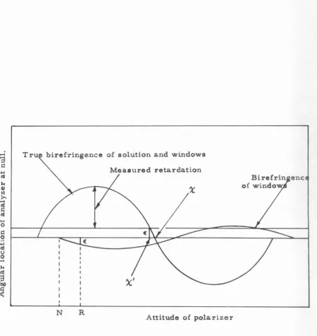
The experimental data then consists of the measure of the
isocline and amount of retardation of the composite system of windows
and birefringent solution by the method outlined in the previous sec -tion. and the measure of the birefringence of the optical cha.racteristlca
of the wtndows by the method of plotting the extinction angle as a. function
of the azimuth of the polarizer already outlined. It is now of
conolder-able importance to establish whether the effect of the windows can be
separated from the composite measurement to obtain the true
-23-where both effects are of the same order of magnitude.
For the small angles under consideration (less than one degree
in either case), both the birefringent medium [M(j3, o)] and the win-dows (M
(
p
,
6 )] are approximated by the matrix (14). The netw w w
effect of the two media is equivalent to the product of the two matrices:
1 0 0 0
0 1 0 p l
f
M({3. o)] [Mw(;3w• ow)J
~ (16)0 0 1 -f> 2
0 -P l ";"')
... 2 1
where p l
=
5 sw 1n2f3 ·w + osin2f3 and F 2 ::o
cos 2{3+
ocos Zf3 , andw w
products of the form owo have been neglected. Matrix (16) is of the
same form a.e matrix (14). Setting the matrix (Me(f3e' ~e)] to
repre-sent the experimental results, this last matrix can be equated term by term with matrix (14), and solving for
f3
ando
it is found that:~2 ::: 2 2
u
o
e
+ ow -2
o
86w cos 2(f3e-f3w)
(17)
tan 2(:3
o
e sin 2f3 e - 6 w sin 2.p w
~24-m.
EX:?ERlMENTAL TECHNIQUE3. 1 Equipment.
To take full advantage of the increase in sensitivity resulting
.from the combination of optical elements described in the previous sec
-tion.
a
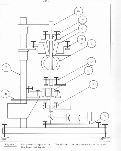
polarimeter head was designed and buUt. With reference toFigures 7, 8, and 9 , the basic movement of the polarimeter (H) is
the one of the transit head, where the concentricity of the a.xie of rota•
tlon ls assured by the conical geometry of the bearing aurfacea.
In accordance with the required movements, two concentric
graduate circles (G) are mounted on the two independent sections of the
system. The upper one, with a least count of 0. 01°, records the post•
tion of the analyzing prism with respect to the lower one. The lower
graduate circle, with a least count of 1 '• is integral with the polarizer
(P), the quarter-wave plate (Q), and the FEM (F).
Both polarizing and analyzing prisms are calcite Glan-.. .rhompaon
polarizer&. The quarter-wave plate is a quartz crystal cut to such a
thickness as to :retard the 5460
R.
wavelength by one-quarter of thiswavelength along its slow axio with respect to the last one.
The Couette cell (C) ls the same one used by Sutera(S) for the
calibration of TMV solutions, with a modified mounting with
mlcro-metdc adjustments for leveling its main axis.
The FEM (F) was built in such a way that an approximately uni·
form spherical sheet of current circulates about its axis. Such
age-ometry produces a uniform magnetic fleld parallel to the axis of
revo-lution of the winding. A unlform magnetic field is required to produce
-25-Figure 7. Diagram of apparatus. The dotted line represents the path of
[image:29.557.68.543.60.653.2][image:30.559.107.425.191.500.2]
[image:31.572.103.447.179.494.2]
-27-,,
uniformly retarded, and no errors result from placing the beam at different locations with respect to the axis oi rotation. The water re-quired ia held in place by a lucite tube with strain-free optical windows. Special provision is made for trapping small air bubbles that develop
in time.
The system can be rotated as a unit, or each part independently, including the quarter-wave plate. Micrometrlc adjustments exist for the three parte. A special indexing plate is also provided eo that the
syotem a.a a unit can be moved 45° from any attitude, which is required
for the determination of the amount o! birefringence. All optical ele-mento are mounted eo that they can further be micrometrlcally adjusted
to perpendicularity to the optical axic of the system.
The complete polarimeter pivots about the poet {P ) and can be
0
swung out of the way of the Couette cell to facilitate its fUline, which
ls usually complicated by small trapped bubbles. The drive (D) of the
inner rotor consists of a synchronous motor, t.wo pairs o!
interchange-able gears, and one interchangeable worm and gear reduction unit.
Motion ia transmitted to the cell through a timing belt that straddleo the post.
The optical bench mounts a concentrated mercury arc lamp and
a system of lenses that produce a narrow beam of light focused at the exit window
oi
the filled Couette cell. The Couette cell uses a rotor which clears a 2 millimeter gap, while the cross section of the beam through the test section is 0. 5 mllllrneters. to eliminate the possibilityof reflections from the walla. A Wratten No. 77 optical fUter selects
0
-
Z9
·
The FEM is driven by a variable tl'ans!ormer from the 120
volt, 60 cycl~ building supply at such
a
level as to produce about 5°
modulation-The photoelectric aystem, bullt by Applled Physics Corporation
of Monrovia, consists of a photomultiplle~:, an amplifier whose gain is
regulated by the amount of light that the photomultiplier receives and
which is tuned to the 60-eycle frequency of the signal transmitted by
the analyzing prism, and a synchronous switching rectifier driven by
the same supply tha.t drives the FEM.
The output of the amplifier gives a direct measure of the amount
of unbalance between the location of the optical assembly and the optical
axes of the system. Synchronous rectiftcatlon is so arranged that the
output signal changes phase in traversblg the null, giving a very clear
indication of the position of the null.
The mercury arc is
an
Osra.m lOOW, andls
driven by a DCpower supply specially built for the purpose.
The whole laboratory is air conditioned and kept at Z0°C
.:t
1°,and the Couette cellls thermostatted by circulating water kept at
Z0°C.!. 0. 01 by a Sargent temperature regulator that operates in thermal
push-pull.
3. 2.. Alignment.
The system is first aligned along the direction of gravity by
means of a precision level. The axes of the polarimeter and the Cou
-ette cell are aligned in sUch a manner. The axis of rotation of the po
-larimeter is made parallel to the direction of gravity by locating a level
-30
-the position oi. the bubble is detectable in any attitude of the system.
The main axis of the Couette cell is aligned by withdrawing the cover
and adjusting the cell Wltil a level placed on it shows the same bubble
position for all positions of the level.
The optical elements are first adjusted ln the horizontal plane
and their cylindrical moWltlnge are made concentric with the axis of
rotation of the system by means of a precision dial gauge.
Finally, the surfaces of the polarizing prisms and the quarter
-wave plate are made perpendicular to the axis o1 rotation. by adjusting
thelr tilt Wltil the reflected image o£ the cross hairs of an a.utocolimator
shows no relative movements as the whole assembly is rotated.
Once the optical system is aligned. a beam o£ light from the
mercury discharge arc is so arranged that ita circular cross sections
at the entrance of the polarizer and the exit o£ the analyzer prisms are well clear of their edges. The beam Is made to focus at the exit
window of the fUled Couette ceU. A 0. 5 millimeter diaphragm at the
entrance window of the Couette cell is located in such a manner that
the light going through it is centered in the 2 millimeter gap. Because
o£ the relative size of the source to the entrance diaphragm. the cross section of the beam is uniform throughout the test section. For this adjustment the Couette cell ls moved in its horizontal plane until the
beam ls centered ln the gap.
In addition to the mechanical alignment, the system is aligned
photoelectrically, in the sense that quadrature between the two prisms
and alignment of the quarter-wave plate is made using the photoelectric
-31-Once the faces of t11e two prisms are aligned to perpendicularity
to the axis of rotation and the beam
oi
light is made concentric withthis axis, a.nd before putting the Couette cell and the quarter-wave plate
in place, the position oi quadrature of tbe two prisms
ts
noted atdU-ferent attitudes of the system. I£ no correction must be made at any
attitude, the two prisms are considered parallel. The sa:me procedure
is used with the qua.rtcr·wave plate, where this is located tn the
appro-priate direction by rotating it untU e,atnctton is obtained when the two
prisms are in quadrature. Finally, the Couette cell is put in place
without windows,and the procedure is again repeated to make certain
that reflections from the walla do not Introduce spurious effects.
The final alignment is electronic, where the phase of the
switching relay of the amplifier is so adjusted that it exactly rectUles
the sine wave that constitutes the output of the amplifier.
3. 3 Data :Handling.
:Preliminary experiments with solutions of Bentonite and TMV
indicated that the system constructed wa.s capable of a ccm.sldera.bly
greater accuracy than any instrument previously built, provided that
the effects of extraneous birefringences introduced by the wtndov.rs
eould be properly accounted for or eliminated.
Considerable attention was given to the matter of obtaining
strain-free windows. The materials tried werel annealed glaaa, an•
nealed fused quartz, and microscope cover slides. To the present,
no material or method of processing has yet been found sucll that the
instrument under consideration cannot detect the presence of
of these were tested, and the best palra were selected.
At low concentrationfl and velocity gradients, the efiect of the windows is significantly large when compared to the birefringence of the solutions, which prompted the development of the corrections,
formulas (17) and (18), and the refinement o£ the measurement tech
-niques. The latter were found to be limited by the· resolution of the
graduate circles and verniers.
To determine the amount of birefringence of the windows and
the location of their optic axis, use ls made of equations ( 15 ). W lth
the Couette ceU filled and all windows in place, the position at which the analyzer makes the photoelectric system traverse the null is noted
at
successive attitudes. The points so obtained describe a sinusoidal curve when plotted versus the attitude of the polarizer. To establishthe position of the
nodes
,
i.e
. ,
the isoclines of the windows, thean
-alyzer positions z1 are assumed to be related to a function yl of the
attitude x 1 :
such that the squared error between the assumed function and the data points is a minimum; that ls to say. choosing
A.
B, and C such thatthe function
is a minimum. Differentiating F wlth respect to A, B, and C ,
setting the results equal to zero, and solving for A, B, and C, yields the fun<:tion that best £ita the data by the method of least squares. The amount of birefringence and angle of isocline of the windows are then
1
c
=
a
arc tan-B
In actual practice, the position of the null z
1 is determined at
euccea-o
0sive intervals of 10 • throughout the ZOO that constitute the range of
the instrument. The data is then reduced by computer (Burroughs 220)
by a fixed program developed for the purpose. For weakly birefringent
solutions, particularly at small velocity gradients, the data ls gathered
by the same method and then corrected for the effect of the windows by
means of equations ( 17) and ( 18 ).
It has been found that the measurement of the windows must be
made for every experiment, even when a number of runs occur in
rapid succession. This is due to the fact that the birefringence of the window changes through time, and that -since the windows must be re-moved at each experiment for cleaning, the positions of their isoclines
also change.
In runs where the concentrations and gradients are sufficiently
large so that they produce effects much greater than the one of the
windows, the simpler and more rapid technique of looking for the null
with polarizer and analyzer in quadrature ls used.
Since it is not practical to determine the position of the isoclines
in the windows at every run. and then establish the quadrature between
polarizer and analyzer, setting the polarizer parallel to the axis of the
windows so that their effect vanishes. a correction must be made to
allow for the small error in quadrature which constitutes the amount o!
birefringence in the window at the reference location where quadrature
.
-
]
...
0~
.
....
2
.,
u 0
-
-34-birefringence of solution and windows
retardation
N R
Attitude of polarizer
Figure 10. Effect of the error in quadrature e on the position of
the isocline and the measured amount of retardation.
[image:38.557.103.552.56.532.2]..
35-In this correction. both the bire.fringences of the combined sys-tem o.f windows plus solution and windows alone are assumed to be represented by sinusoidal functions of the attitude of the polarizer. With reference to FigurelO, the reference attitude R ls chosen so that it is fairly close to the isocline of the window, whose position is not yet avaUa.ble. Setting polarizer and analyzer in quadrature at this position. there will be a small error ~ between the position at which polarizer and analyzer are locked and the true location of quadrature. With reference to FigurelO, when the rotor is set in motion. the solu-tion exhibits lts birefringence so that when the null is again sought by rotating the assembly of polarizer and analyzer, this will appear at a
'
location X where the error due to the window exactly balances the birefringence of the combined system. Once the data for the window ls reduced, the error tn quadrature becomes ava.Uable, and the actual position of the isocline of the system ls given by the relation:
X
=
x
' •
t
arc sln(N-R)The amO\Ult of SBR muot also be corrected for the amount of retardation represented by the error ln quadrature between both prisms. Since the error ls equivalent to shifting the base line of a sinusoidal curve, the correction is simply additive.
[image:41.565.74.507.128.566.2]
-38-Sample I. TMV lot 0504, 0510-61 (lot 1 ), at 0. 20 per cent in 0. 01 M
Versene, pH 7. 5, 24,630 RPM, 60° bar. Exposures at speed and at
4 minute intervals thereafter. Some evidence of presence of very small amount of aggregate.
Sample 2. TMV lot 0609-61 (lot 2), at 0. 20 per cent in 0. 01 M
Versene, pH 7. 5, 24, 630 RMP, 30 mm cell, 60° bar. No evidence
[image:42.562.119.437.84.191.2]of presence of aggregate.
-40
-Experimental Results
0
/o
TMVby 0/
o
SBMV by Ratio Retardation Viscosityweight weight TMV/SBMV per unit Centipoise
velocity radlent
sec/em
o
.
375 2. 30 1. 142o
.
275 1. 0940. 264 1. 61
0
.
194 1. 16o
.
190 1. 066o
.
181 1. 08o
.
101 1. 0370. 096
o
.
571. 020 1. 037
o
.
465 none 1. 0180. 244 1. 008
o
.
121 0. 9880. 359
o
.
123 2. 92 2. 05 1. 1420. 230
o
.
079 2. 91 1. 28 1. 074o
.
101 0. 035 2. 97o
.
58 1. 0370. 382 0. 382 1. 00 2. OS 1. 133
0. 275
o
.
275 1. 00 1. 45 1. 104o
.
333 1.oao
o
.
31 1. 85 1. 1520. 166
o
.
540 0. 31 0. 92 1. 0700
Note: all experiments were conducted at 20. 00 ~ 0. 01
c
.
All solu -tions ln 0. 01 M Versene, at pH 7. 4 • Viscosity of Versene solution:7
6
5
.
s
CJ-o<
-1:: 4
0
.
....
...
~
~
!J
G) 3~
~
0
....
g
2
~
1
0
-41-•
TMV lot 1.0
TMV lot 2.0 5 10 15 20 25 30
Velocity gradient, aec -l.
[image:45.559.93.547.65.557.2]47°
><
..
45°
4)
~
.
....
...
g
43°
til
.
...
...
0
.,
....
bO
1=1
<
47°
45°
43°
-4
2-Fast axis
Slow axis
0. 181%
Slow axis
0, 2.66a;o
Fast axis
Slow axis
0 5 10 15 2.0 25 30
Velocity gradient, sec -l
[image:46.560.72.507.71.601.2]
-43-O.l94o/o
~ I I T I T T -:;;,;
1-
0
0
0
Faet axie().
.D
-u
1-0
0
u
...
-
0
-
Slow axis-o
I I I I I I0 5 10 15
Velocity gradient, sec -l
Figure 16. Experimental reeulta. Angle of isocline of eolutione of TMV lot 2 ae a function ot velocity gradient. The stream line ie at X
=
0 .-()
-""-.)
[image:47.560.82.543.85.591.2]-0
I
\
'
\ \
-44-0
o.
1o.z
0.30.4
Concentration,
o/o
by weight.Figure 17. Amount of retardation per unit velocity gl'adient as a function of;,
[image:48.559.143.536.85.612.2]7
6
8
5u
-o<:
~
0 4
.
......
Ill
'tl
1-<
Ill
....
t)
1-<
3
....
0
§
0
e
<:
2l
0
0
0
0
0 5
-4
5-0. 3 59o/o TMV, 5-0. l23o/o SBMV
0. 275o/o TMV, 0. 275o/o SBMV
0. l66o/o TMV, 0. 540o/o SBMV
10 15 20 25
-1
Velocity gradient, sec
Figure 18. Typical data on the amount of retardation of mixtures of TMV and SBMV as a function of velocity gradient.
[image:49.559.106.552.72.606.2]-
I-
0_..().
-0 ..rL
t- ...
t-I
0 5
Figure 19.
I
0
v
I10
-
46
-Fast axis
Slow axis
0. 275% TMV, 0. 275% SBMV
Slow axis
0. 166o/o TMV, 0. 540% SBMV
T I
,...
u
-0-Faat axis
0
Slow axisI
v
lf"""'15 20 25
-1 Velocity gradient, sec
_)
-~
30Angles of isocline corresponding to the experiments
[image:50.563.70.550.74.621.2]2. 5
2.0
s
v-
v4)
.,
o<
1.5
!=:
0
....
....
aS ~
,...
!!
Q)1.0
,...
v
[image:51.559.99.536.80.665.2]....
...
....
v
X.
{/)o.
50
-47-0
TMV /SBMV=
2. 90 TMV /SBMV :c 1. 0
•
TMV /SBMV :s 0. 3Pure TMV
0 0. 1
TMV concentration,
%
by weight.Figure 20. Amount of retardation per unit velocity
gradient aa a function of concentration of TMV in
o/o
by weight, of mixtures of TMV8
u
-
uQ)
all
o<
2.0..
>
~
1.9 f-4
lfl.
t"'l
[image:52.560.93.548.56.658.2]0 1.8
... 0 r::
0 1.7
....
....
C1l
'0
...
C1l 1.6
....
Q)
...
u
....
1.5:';:l u
8.
(/)
-
48-0 1 2 3 4
o.
5 6 7 8 9Concentration of SBMV,
o/o
by weight.Figure 21. Specific retardation of TMV -SBMV mixtures,
at a TMV concentration of 0. 3%, as a function
of the amount of SBMV in the mixture.
Gil
~
-
Gil 5:'"I
~
:>-..,
...
CIQ 0
u II)
...
>
u
...
...
...
u8.
(f)-4 9-0. 150
Pure TMV
o.
1000
TMV /SBMV=
2. 90 TMV/SBMV
=
1.00.05
•
TMV/SBMV=
0.3+
Pure SBMV
0
0 0. 1 0.2 0. 3 0.4 0. 5
Concentration,
o/o
by weight.Figure 22. Specific viscosity of TMV, SBMV, and m ixtures of TMV and SBMV, as a function of concentration.
The viscosity of the solvent (water+ versesne) Tl
is 0. 998 centipoise. The spetific vi•coaity of 8 the mixture• is plotted as a function of the
[image:53.562.87.551.13.622.2]-5
0-+
55 0. 359o/o TMV, 0. 123% SBMV
53
Fast axis
51
+
49
•
+
•
+
+><
•
•
47
-.,
~
...
...
u 45
0
a:t
...
~
0 43
.,
...
•
bO ~
<
47•
+
Slow axis
39
+
+
Data37
•
Data corrected for error in quadrature35
0
Data corrected for birefringence of windows+
0 5 10 15 20 25 30
[image:54.562.94.551.67.643.2]Velocity gradient, em/sec -1
.
Figure 23. Effect of corrections on the position of the angle
-
51
-V. DISCUSSION OF EXPERlM:ENTAL RESULTS
AND CONCLUSIONS
Some of. the most recent and accurate meaaurem.ente of the SBR
of TMV solutions made by Leray<
9
> indicate that at low shear rates and concentrations, some departures from the results predicted by thePeterlln and Stuart theory appear. Observations show that the angle 0
of isocline, even though it tends towards 45 when the velocity gradi-ent approaches zero, does so up to a certain point and then starts leveling off
at
the lower velocity gradients.Assuming that the phenomenon ie not due to extraneous bire-fringences, the abnormal behavior of the angle of isocline can be
ex-plained by assuming that at the low velocity gradients there exists in
the solution
a
partial structurization of the TMV particles Vllhichle
bro-ken up at the higher shear rates. This structurizatton can be produced
by weak chemical bonds among the particles, which would tend to form some sort of organization of the material. Evidence of such
a.
phe-nomenon was found by H-earst a.nd Vinogra.d(lO) in experiments madewith TMV in the ultracentrifuge, in which t-he sedimentation behavior
was found to be strongly concentration dependent. To explain their re• sults, they tentatively proposed that an alignment is brought about among the macromoleculea as a result of chemical interactions among them. In SBR, the result is such that, even though the forceo tending to align the particles are small, a number of particles align themselves simultaneously as a Wlit, the net result being that there is a larger
quantity of aligned material, which produces an optical efiect equiva
-sz-though. that if such an effect exists, it must be of such a ftature that it
does not affect the amount of birefringence, since no evidence of this
effect ts found in analyzing the data on the amount of birefringence.
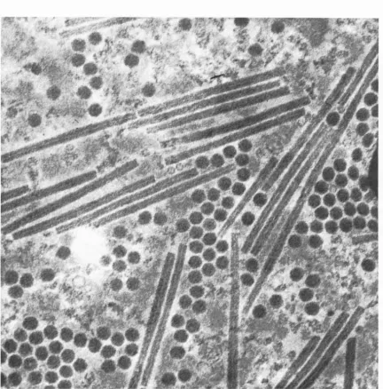
To test these ideas, a number of samples of concentrated TMV
solutions were obtained from the Department and Laboratories of Nu•
clear Medicine and Radiation Biology, of the School of Medicine, o£ the University of California at Los Angeles.· These samples were highly
monodleperse and very uniform in length, as attested by the ultracen
-trifuge runs made on them, shown
tn
Figure 12 and the electron micro-scope photograph shown in Figure 11. These samples were dUuted to
concentrations ranging from 0. 4 per cent to 0. 1 per cent by weight, in
0. 01 molar Versene at a pH of 7. 4 • The coocentration of each dilution
was determined with a Zeiss PMO U spectrophotometer. A number of
determina.tione of the SBR of these solutions was made a.t velocity gra -- 1
dients ranging from 0. 3 to 31. 1 sec. •
The experimental results showed that the amount of SBR of these
TMV solutions is linear wlth velocity gradient, as shown in Figure 14
and as predicted by theory. A small departure from linearity was ob·
served at the higher velocity gradients. These results also confirm that the amount of specific SBR, defined as the amount of retardation per unit veloclty gradient, is linear wtth respect to concentration. as shown
tn
Figure 17.Concerning the angle o£ isocline. no satisfactory proof was ob·
tained to substantiate the claim that a departure from the Peterlin and Stuart theory exists at low velocity gradients. It was indeed observed
-ure 23 where a representative case is shown. but this depart-ure dis•
appears when the corrections for the error ln quadrature and the
bire-fringence ol. the window are applied.
The position of the streamline with respect to which the 45°
location is established was always determined by averaging the
posi-tion of the isoclines of the fast axis of the solution in the clockwise
direction of rotation. and the slow axis in the counterclockwise direction of rotation. This method yields the position oi the streamline to a.
de-gree of accuracy comparable to the one of the determination of the
iso-cline, which is estimated to be of the order
of.:!:.
0. 10° at the lowervelocity gradients.
It
has always been observed that in linearlyextra-polating the isocline to zero shear, the value for zero shear always
falls short of the 45° value predicted by the theory, the discrepancy
being most severe in those cases where the laocline departs more
radically from the predicted monotonic approach to the 45° value.
This behavior is considered to be due to effects of extraneous
bire-fringences not accounted for in the simplifications made to arrive at a
directly applicable correction.
In view of these results, it is apparent that further refinements
of the mea.surtng techniques will be possible if
a
method is found for·eU.mlna&g the e>..•tl•aneous birefringences ol. the windows. Due to this, consideration is being given to an apparatus to be buUt in which the
llquid samples are contained in place by the surfaces of the optical ele•
mente such as the polarizer and the quarteJ"-wave plate, in order to
eliminate as many sources of stray birefringence as possible.
Taking into account the difficulties Introduced by extraneous
-54-permit detenntnations of the angle of isocline accurate to one degree
for a retardation per unit length of 1 x 10•9 • As a comparison, a
typ-ical instrument f.or SBR studies, such as the one built by the Rao In-strument Company, yields accuracies of the order of one degree per
-8
7. 5 x 10 relative retardation as descll>ed by Edsall, Rich. and
Gold-stein ( 11), and the same Rao instrument modified for photoelectrlc
ob-(1 Z)
servatlon by Zimm only increases t..lle accuracy to one degree per
7 x 10•9 relative retardation.
In view of the above results, 1t was decided to apply tho
informa-tion obtained on the SBR of TMV; and the measuring technique developed,
to the question whether for dUute solutions !or which existing theories
are supposed
to
be valid, there are signlflc:ant hydrodynamicinterac-tions among particles which might explain the discrepancies observed
between different methods for characterizing macromolecules, such a.a
viscometry, SBR. sedimentation, and transient Kerr e!fect.
That hydrodynamic interactions might contribute significantly to
the tnacroscopic characteristica of dilute solutions of submicroscopic particles was proposed by Collins and Wayland(l3) to explain the vts·
coelty behavior of mixtures of TMV and polystyrene latex spheres,
(PSL), ae a function of the concentratl~ of both particles. In the first
phase of the experimental program of whlch this study is a part, they
found that the specific viscosity of mixtures of TMV and PSL was higher than that predicted by the elmple addition of the specific vis•
cosities of the components by a term proportional to the product of the concentrations of the two particles. In expla!nSn.g this result, they
·55-of the rods to assume an orderly rotational motion in shear
flow
whichleads to
an
increase in viscosity.If the orderly rotational motion of the rod·like particles is
tampered with by a random hydrodynamic lnteraction,such as the one
that would be produced by the presence of spheres, a decrease of the
SBR of the mixture with respect to the SBR of pure TMV solutions at
the same concentration should be observed, since no direct contribution
to the SBR of the mixture can be expected from the spherical particles,
which show no optical asymmetry regardless of orientation in shear
flow.
To see what infot-mation could be obtained from mixtures of
TMV and spherical particles, lt was decided to use a spherical virus
compatible with TMV, since the PSL had proven to have a surface
chem-istry that ha.d produced considerable difficulties in previous
expert-ments, and furthermore was so large that
tt
would have scattered toomuch light for good optical experiments. The choice !ell upon southern
bean mosaic virus (SBMV), which is a spherical virus of 2. 52 x 10•6 em
diameter.
A program was started in the laboratory to secure this virus
by planting a number of southern bean plants and infecting their leaves
with an avallable sample of the virus. After an appropriate tirne, the
leaves were collected and the virus extracted according to the technique
described by Konrad
04
>.
Electron microscope photographs o£ the ob·tained vlrus show that it ls quite pure, as can be seen in Figure 13.
The presence of some particles that have a dark center is attdbuted to
-56-The two viruses were mixed in such proportions as to obtaln
th1•ee maln sets of solutions where the proportion by weight of TMV
to
SBMV was zoespectively 3:1 , 1:1, and 1:3 ,
at
a nominal TMVconcen-tration of 0. 3 per cent by weight. Experiments were made at the
original cOJK:entrations and at dUutions of the original mixtures.
To interpret the information obtained from these experiments,
attention must first be given to the theoretical results given by equation
(A60 ), which predicts that the amount o£ reta.J."dation is a linear functioo
of the viscosity felt by the particle. This viscosity, according to the best present theories, seems to lie somewhere between the viscosity
of the matrix fluid and that of the solution. That the amount of SBR is
a linear function of the viscosity was checked experimentally by Sutera
(loc. cit. ), who purposely altered the viscosity of the solvent by using
an 85 per cent glycerine solution for the matrix fluid, which. at Z0°C,
is approximately 100 times as viscous as water. He observed a
ten-fold increase in the amount of SBR for equivalent concentrations and
velocity gradients. That the observed increase is not of the same
order of magnitude of the increase in viscosity is explained by the fact
that the amount of SBR also depends on the df.fference in index of
re-fraction between the particle and the matrix fluid. The lesser the dif
-ference the less marked the effect, as ln this case, where the index
of refraction of the mixture of glycerine and water is considerably
higher than the one of water, which results ln a smaller difference with
the index of refraction of the particle, and thus a smaller effect.
It should further be noted that the addition of a small number of
Figure 24.
-57-TMV /SBMV
=
2. 90
I
0TMV /SBMV = 1. 0
0 0
0
I
00 0
TMV /SBMV
=
0. 30 0 0 0
0 0 0
I
0 0 0
0
0
0 0 0 0