intermediate temperature solid oxide fuel
cell cathodes
Ailbhe Gavin
A thesis submitted in partial fulfillment of the requirements
for the degree of Doctor of Philosophy
at the University of Dublin, Trinity College
I declare that this thesis has not been submitted as an exercise for a degree at this or
any other university and it is entirely my own work, except where otherwise cited.
I agree to deposit this thesis in the University’s open access institutional repository or
allow the Library to do so on my behalf, subject to Irish Copyright Legislation and
Trinity College Library conditions of use and acknowledgement.
Ailbhe Gavin
2018
University of Dublin, Trinity College
In recent years it has become clear that a move to cleaner, more efficient energy
genera-tion is required. Solid oxide fuel cells (SOFCs) are a promising technology for electricity
generation as they can overcome combustion efficiency limitations, and can utilise a
range of fuels, including hydrogen, methanol and ethanol. However, there are a
num-ber of challenges currently associated with them. High temperatures are required for
operation of current generation fuel cells, leading to high costs and accelerated
perfor-mance degradation. Recently, the development of more efficient SOFCs which operate
at intermediate temperature, in the region of 600–1000 K, has been investigated. Both
optimisation of the materials currently used for components for SOFCs, and
devel-opment of alternative materials have been considered as methods of improving their
efficiency. The cathode, at which the oxygen reduction reaction takes place, currently
requires a high operating temperature due to poor catalytic activity for the reaction at
lower temperature, thus development of improved materials for intermediate
tempera-ture SOFCs is of great importance.
In this thesis, we first investigate LaMnO3, which has been widely used in high
tem-perature SOFCs, examining the performance of density functional theory (DFT) and
post-DFT methods in modelling its structural and electronic properties. Our results
show that DFT fails to model the structural and electronic properties of LaMnO3
cor-rectly and although hybrid DFT can give an improved description of the structure, it
does not correctly model features in the electronic density of states. The PBEsol + U
functional is used to model the low index surfaces, and oxygen vacancy formation in
the bulk and at these surfaces are examined. Nudged elastic band calculations are used
to determine the activation energy for oxygen migration in bulk LaMnO3. The
intro-duction of alkaline earth defects to bulk LaMnO3 in investigated, considering both the
site selectivity and the charge compensation mechanism. Larger dopant cations (Ca,
Sr, Ba) are found to have lower formation energies on the La site, while the smaller
Mg cation shows preference for the Mn site. For all defects, charge compensation by
hole formation is preferred over oxygen vacancy formation.
Secondly, the layered Ruddlesden-Popper oxide La2NiO4 is examined, which has
at-tracted attention due to its good ionic and electronic conductivity in the
interme-diate temperature range, and stability under SOFC operating conditions. As the
Ruddlesden-Popper structure can accommodate both oxygen vacancies and
intersti-tials, both are modelled in bulk La2NiO4 and at its low index surfaces, to establish
the dominant oxygen defects. As interstitial defects are found to be dominant, nudged
elastic band calculations are used to determine the mechanism and activation energy
for oxygen interstitial migration, with the lowest activation energy found to be
signifi-cantly lower than was predicted in LaMnO3. Sr and Fe defects are introduced to both
the La and Ni site, to determine their site selectivity and charge compensation
mecha-nism, with Sr defects having lower formation energies on the La site, and Fe defects on
the Ni site. Under SOFC operating conditions, doping with Sr is compensated by the
formation of delocalised, unbound holes, which will improve the electronic conductivity
of the material. Doping with Fe is compensated by the formation of oxygen
intersti-tials, which can improve the ionic conductivity, but strong binding of the defect will
limit the improvement.
Finally, LaCrO3 is investigated as a potential mixed ionic and electronic conductor.
The origin of the charge carriers in LaCrO3 and Sr-doped LaCrO3 is established,
con-sidering intrinsic and extrinsic defect formation. The thermodynamic transition levels
are calculated, allowing identification of defects with low formation energies and shallow
transition levels. The activation energy for oxygen migration in bulk LaCrO3 is found
to be significantly higher than in either La2NiO4 and LaMnO3, therefore La2NiO4 and
First and foremost, I would like to thank my supervisor, Prof. Graeme Watson, for his
expertise and advice on the project. Thanks to the Watson group members, past and
present, for being a mine of information for various aspects of the project, and for
making the group an enjoyable place to work: Dr Jeremy Allen, Dr Mario Burbano, Dr
John Carey, Dr Umadevi Deivasigamani, Dr Patrick Keating, Dr Aoife Kehoe, Aoife
Lucid, Aoife Plunkett, Julia Savioli, Swetanshu Tandon, and Douglas Temple.
I would like to thank SFI for funding, without which this research would not have
been possible. I would also like to acknowledge the computing resources on which
the calculations in this thesis have been performed: Research IT for maintaining the
Kelvin, Lonsdale and Pople clusters, and ICHEC for computing time on Fionn.
I wish to express my gratitude to all my friends, equestrian and elsewhere, for providing
me with welcome distractions throughout the past few years. A huge thank you also to
Shaun, for his endless patience and support during my postgraduate studies. Finally,
thank you to my family for supporting my education over the years.
1. A. L. Gavin and G. W. Watson, Modelling the electronic structure of
orthorhom-bic LaMnO3, Solid State Ionics, 2017, 299, 13–17
2. A. L. Gavin and G. W. Watson, Modelling oxygen defects in orthorhombic
LaMnO3 and its low index surfaces, Phys. Chem. Chem. Phys., 2017, 36, 24636–
24646
3. A. L. Gavin and G. W. Watson, Defects in orthorhombic LaMnO3 – ionic versus
electronic compensation,Phys. Chem. Chem. Phys., 2018, 20, 19257–19267
1. Irish Atomic Simulators Meeting 2016, University College Dublin, Modelling of
LaMnO3 for intermediate temperature solid-oxide fuel-cell cathodes
2. E-MRS Spring Meeting 2016, Lille, France, Modelling of defects in LaMnO3 for
intermediate temperature solid oxide fuel cell cathodes
3. Dublin Chemistry Postgraduate Conference 2016, Trinity College Dublin,Defect
modelling in LaMnO3 for cathodes in intermediate temperature solid oxide fuel
cells
4. MRS Fall Meeting 2016, Boston, USA,Defect Engineering in LaCrO3 to develop
a p-type semiconducting oxide
5. ACS Spring Meeting 2017, San Francisco, USA,Assessing the potential of LaCrO3
as a p-type semiconducting oxide
6. ACS Spring Meeting 2017, San Francisco, USA, Modelling La2NiO4 for solid
oxide fuel cell cathode applications
Declaration of Authorship iii
Summary iv
Acknowledgements vi
Publications vii
Conference Talks viii
List of Figures xiii
List of Tables xv
List of Abbreviations xvii
1 Introduction 1
1.1 Fuel Cells . . . 2
1.2 Solid oxide fuel cells . . . 4
1.2.1 Solid oxide fuel cell operation . . . 4
1.3 Perovskite Oxides . . . 7
1.3.1 Goldschmidt tolerance factor . . . 8
1.4 Ruddlesden-Popper oxides . . . 10
1.5 Cathode Materials for SOFCs . . . 11
1.5.1 Previous studies on LaMnO3-based SOFC cathodes . . . 14
1.5.2 Previous La2NiO4+δ studies for SOFC cathodes . . . 18
1.5.3 Previous studies on LaCrO3 for use in SOFCs . . . 21
1.6 Oxygen diffusion in perovskite-based materials . . . 23
1.7 Thesis outline . . . 24
2 Computational Theory 27 2.1 Quantum chemistry . . . 27
2.1.1 The Schr¨odinger Equation . . . 27
2.1.2 The Born-Oppenheimer approximation . . . 28
2.2 Quantum chemistry methods . . . 30
2.2.1 The Hartree model . . . 30
2.2.2 The Hartree self-consistent field model and variational principle 30 2.2.3 Slater Determinant . . . 31
2.2.4 The Hartree-Fock method . . . 32
2.2.5 Density Functional Theory . . . 34
2.2.6 DFT + U . . . 38
2.2.7 Hybrid DFT . . . 39
2.2.8 Density Functional Perturbation Theory . . . 41
2.3 Solid state simulation . . . 41
2.3.1 Periodic boundary conditions . . . 41
2.3.2 Brillouin zone and k-points . . . 42
2.3.3 Basis sets and pseudopotentials . . . 44
2.3.4 Electronic and geometric optimisation . . . 45
3 Computational Methods 47 3.1 Structural optimisation . . . 47
3.2 Electronic analysis . . . 50
3.2.1 Band structure . . . 50
3.2.2 Electronic density of states . . . 51
3.3 Defect calculations . . . 52
3.3.1 Neutral defect formation . . . 52
3.3.2 Charged defect formation . . . 53
3.3.3 Chemical potentials and oxygen partial pressure . . . 53
3.3.4 Thermodynamic transition levels . . . 55
3.3.5 Nudged elastic bands . . . 57
3.4 Surface simulation . . . 58
3.4.1 Tasker surfaces . . . 58
3.4.2 Slab model . . . 59
4 Structural and electronic properties of LaMnO3 63
4.1 Introduction . . . 63
4.2 Methodology . . . 66
4.3 Structural properties of LaMnO3 . . . 67
4.4 Electronic and magnetic structure of LaMnO3 . . . 70
4.4.1 PBEsol + U electronic structure . . . 72
4.5 Low index surfaces of LaMnO3 . . . 73
4.5.1 The {010} surface . . . 74
4.5.2 The {100} surface . . . 75
4.5.3 The {111} surface . . . 76
4.5.4 The {110} surface . . . 77
4.5.5 The {101} surface . . . 78
4.5.6 The {001} surface . . . 79
4.5.7 The {011} surface . . . 80
4.5.8 Summary . . . 81
4.6 Conclusions . . . 83
5 Defect properties of LaMnO3 85 5.1 Introduction . . . 85
5.2 Methodology . . . 88
5.3 Oxygen vacancy formation . . . 92
5.3.1 Oxygen chemical potential and partial pressure . . . 92
5.3.2 Bulk LaMnO3 . . . 94
5.3.3 Low index surfaces of LaMnO3 . . . 95
5.4 Oxygen vacancy migration in bulk LaMnO3 . . . 98
5.5 Alkaline earth defect formation in LaMnO3 . . . 99
5.5.1 La site doping . . . 100
5.5.2 Mn site doping . . . 106
5.6 Conclusions . . . 113
6 La2NiO4 for IT-SOFC cathodes 115 6.1 Introduction . . . 115
6.2 Methodology . . . 122
6.3 Structural properties of La2NiO4 . . . 126
6.4 Electronic and magnetic structure of La2NiO4 . . . 126
6.5 Oxygen defects in bulk La2NiO4 . . . 127
6.5.1 Oxygen chemical potential and partial pressure . . . 127
6.5.2 Oxygen vacancies . . . 128
6.5.4 Oxygen migration in bulk La2NiO4 . . . 131
6.6 Low index surfaces of La2NiO4 . . . 133
6.6.1 The {010} surface . . . 134
6.6.2 The {100} surface . . . 134
6.6.3 The {001} surface . . . 136
6.6.4 The {110} surface . . . 136
6.6.5 The {101} surface . . . 137
6.6.6 The {111} surface . . . 138
6.6.7 The {011} surface . . . 139
6.6.8 Discussion . . . 140
6.6.9 La2NiO4 surface oxygen vacancies . . . 141
6.6.10 La2NiO4 surface oxygen interstitials . . . 143
6.7 La- and Ni-site doping in La2NiO4 . . . 144
6.7.1 Combined isolated defects . . . 145
6.7.2 Defect clusters . . . 147
6.8 Conclusions . . . 152
7 LaCrO3 as a novel solid oxide fuel cell cathode 155 7.1 Introduction . . . 155
7.2 Methodology . . . 158
7.3 Bulk properties of LaCrO3 . . . 160
7.3.1 Functional testing . . . 160
7.3.2 PBEsol + U . . . 163
7.4 Defect properties of LaCrO3 . . . 164
7.4.1 Thermodynamic stability of LaCrO3 . . . 164
7.4.2 Defect formation and transition levels . . . 166
7.4.3 Defect formation under SOFC operating conditions . . . 171
7.5 Oxygen migration in LaCrO3 . . . 173
7.6 Conclusions . . . 174
8 Conclusions and future work 177 8.1 Conclusions . . . 177
8.2 Future work . . . 179
1.1 Schematic of a solid oxide fuel cell . . . 5
1.2 Three-phase boundary in a solid oxide fuel cell . . . 6
1.3 Ideal cubic perovskite structure . . . 7
1.4 Goldschmidt tolerance factor of the perovskite structure . . . 8
1.5 Distorted perovskite structures . . . 10
1.6 An+1BnO3n+1 Ruddlesden-Popper oxides . . . 11
1.7 Diffusion mechanisms for oxygen ions in perovskites and perovskite-based materials . . . 23
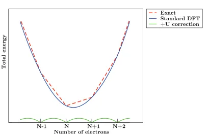
2.1 Total energy profile as a function of the number of electrons . . . 39
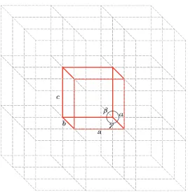
2.2 3× 3 ×3 expansion of a unit cell . . . 42
2.3 Schematic band structure of the first Brillouin zone . . . 43
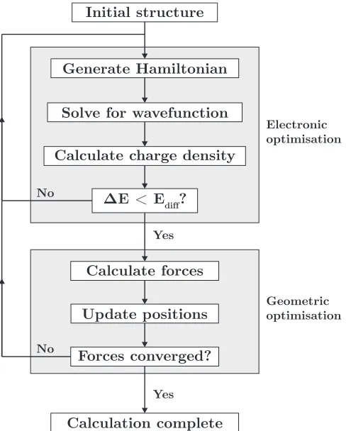
2.4 Schematic of the iterative process for optimisation . . . 46
3.1 Murnaghan equation of state fit to energy-volume data for LaMnO3 . . 48
3.2 Thermodynamic transition level diagrams for a notional binary oxide . 56 3.3 Tasker classification of surfaces . . . 59
3.4 Different terminations of the LaMnO3 {100} surface . . . 60
3.5 Wulff construction of equilibrium crystal strucutre . . . 62
4.1 LaMnO3 unit cell . . . 64
4.2 EDOS for LaMnO3 from functional testing . . . 71
4.3 LaMnO3 band structure calculated using PBEsol + U . . . 72
4.4 Relaxed surface slab of the{010} surface of LaMnO3 . . . 74
4.5 Relaxed surface slab of the{100} surface of LaMnO3 . . . 75
4.6 Relaxed surface slab of the{111} surface of LaMnO3 . . . 76
4.7 Relaxed surface slab of the{110} surface of LaMnO3 . . . 78
4.8 Relaxed surface slab of the{101} surface of LaMnO3 . . . 79
4.9 Relaxed surface slab of the{001} surface of LaMnO3 . . . 80
4.10 Relaxed surface slab of the {011} surface of LaMnO3 . . . 81
4.11 Wulff plot of the equilibrium crystal morphology of LaMnO3 . . . 82
5.1 Oxygen migration paths in LaMnO3. . . 87
5.2 Plot showing region of stability for LaMnO3 spanned by ∆µLa and ∆µMn 93
5.3 Oxygen vacancy migration pathways in LaMnO3 . . . 98
5.4 Energy profiles for oxygen migration in LaMnO3 . . . 99
5.5 La ions neighbouring O vacancies in LaMnO3 . . . 102
5.6 PEDOS for the Ca dopant on the La site . . . 105
5.7 Partial charge density plot for the defect state in Ca-doped LaMnO3 . . 105
5.8 Mn ions neighbouring an O1 vacancy in LaMnO3 . . . 108
5.9 Mn ions neighbouring an O2 vacancy in LaMnO3 . . . 109
5.10 PEDOS for the alkaline earth defect on the Mn site . . . 112
6.1 Unit cell of orthorhombic La2NiO4 . . . 116
6.2 EDOS for La2NiO4 calculated using PBEsol + U . . . 127
6.3 Plot showing region of stability for La2NiO4 spanned by ∆µLa and ∆µNi 128 6.4 Structure of the oxygen interstitial in La2NiO4 . . . 131
6.5 Oxygen migration paths in La2NiO4 . . . 132
6.6 Relaxed surface slab of the{010}surface of La2NiO4 . . . 135
6.7 Relaxed surface slab of the{100}surface of La2NiO4 . . . 135
6.8 Relaxed surface slab of the{001}surface of La2NiO4 . . . 136
6.9 Relaxed surface slab of the{110}surface of La2NiO4 . . . 137
6.10 Relaxed surface slab of the {101}surface of La2NiO4 . . . 138
6.11 Relaxed surface slab of the {111}surface of La2NiO4 . . . 139
6.12 Relaxed surface slab of the {011}surface of La2NiO4 . . . 140
6.13 Wulff plot of the equilibrium crystal morphology of La2NiO4 . . . 141
6.14 Structure of the defect clusters for Sr doping compensated by an O vacancy148 6.15 PEDOS of undoped and doped La2NiO4 . . . 149
6.16 Partial charge density plot for the defect peak in Sr-doped La2NiO4 . . 150
6.17 Structure of the defect cluster for Fe doping compensated by an O in-terstitial . . . 151
7.1 LaCrO3 unit cell . . . 158
7.2 XPS and XAS spectra of LaCrO3 . . . 160
7.3 EDOS of LaCrO3 from functional testing . . . 162
7.4 PEDOS and band structure of LaCrO3 calculated using PBEsol + U . 164 7.5 Plot showing region of stability for LaCrO3 spanned by ∆µLa and ∆µCr 165 7.6 Sites of the point defects in the LaCrO3 supercell . . . 167
7.7 Transition level diagrams under oxygen-rich and oxygen-poor chemical potential limits . . . 168
7.8 Transition level diagrams for SOFC operating conditions . . . 172
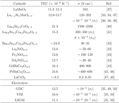
1.1 Thermal expansion coefficients and experimentally measured
conductiv-ity for cathode and electrolyte materials . . . 12
4.1 Structural data for LaMnO3 . . . 69
4.2 Magnetic moment and band gaps for LaMnO3 . . . 70
4.3 Surface energies, surface coordination and Mn-O bonds cleaved in the low index surfaces of LaMnO3 . . . 73
5.1 Formation energies and magnetic ordering of LaMnO3 and its competing phases . . . 92
5.2 Chemical potential limits, for LaMnO3 . . . 93
5.3 Oxygen chemical potential and temperature relationship forpO2 = 0.21 atm, p◦ = 1 atm . . . 94
5.4 Oxygen vacancy formation energies for bulk LaMnO3 under IT-SOFC operating conditions . . . 95
5.5 Oxygen vacancy formation energies for the low index surfaces of LaMnO3 96 5.6 Chemical potential of La, Mn, O, and the alkaline earth dopants for the given oxygen chemical potentials, in eV . . . 100
5.7 Formation energies of the combined isolated defects on the La site of LaMnO3 . . . 101
5.8 Formation energies of the defect clusters on the La site of LaMnO3 . . 103
5.9 Binding energy of defect clusters on the La site of LaMnO3 . . . 104
5.10 Formation energies of the combined isolated defects on the Mn site of LaMnO3 . . . 107
5.11 Formation energies of the defect clusters on the Mn site of LaMnO3 . . 110
5.12 Binding energy of defect clusters on the Mn site of LaMnO3 . . . 111
6.1 Structural properties of La2NiO4 . . . 126
6.2 Formation energies and magnetic ordering of La2NiO4and its competing phases . . . 128
6.3 Chemical potential limits for La2NiO4 . . . 129
6.4 Oxygen vacancy formation energies for bulk La2NiO4 . . . 129
6.5 Oxygen interstitial formation energies for bulk La2NiO4 . . . 131
6.6 Activation energies for oxygen interstitial migration in bulk La2NiO4 . 132
6.7 Surface energies, surface coordination and Ni-O bonds cleaved in the low index surfaces of La2NiO4 . . . 134
6.8 Oxygen vacancy formation energies for the low index surfaces of La2NiO4142
6.9 Oxygen interstitial formation energies, in eV, for the low index surfaces of La2NiO4 . . . 144
6.10 Chemical potential of La, Ni, O, and the alkaline earth dopants for the given oxygen chemical potentials, in eV . . . 145 6.11 Formation energies of the combined isolated defects in La2NiO4 . . . . 146
6.12 Formation and binding energies of the defect clusters in La2NiO4 . . . . 148
7.1 Structural data for LaCrO3 . . . 163
7.2 Formation energies and magnetic ordering of LaCrO3 and its competing
phases . . . 165
7.3 Chemical potential limits, for LaCrO3 . . . 166
7.4 Formation energies of neutral p-type intrinsic defects in LaCrO3 . . . . 169
7.5 Formation energies of neutral n-type intrinsic defects in LaCrO3 . . . . 169
7.6 Formation energies of neutral extrinsic defects in LaCrO3 . . . 170
7.7 Chemical potentials under SOFC operating conditions . . . 171
7.8 Formation energies of neutral defects in LaCrO3 under SOFC operating
B3LYP Becke,3 parameter, Lee-Yang-Parr functional
CBM Conduction Band Minimum
CPLAP Chemical Potential Limits Analysis Program
DFT Density Functional Theory
EDOS Electronic Density of States
GGA Generalised Gradient Approximation
HF Hartree-Fock
HSE Heyd, Scuseria and Ernzerhof functional
IT Intermediate Temperature
LDA LocalDensity Approximation
LEIS Low Energy Ion Scattering
LSDA LocalSpin Density Approximation
MD MolecularDynamics
NEB Nudged Elastic Band
ORR Oxygen Reduction Reaction
PAW Projector AugmentedWave
PBE Perdew-Burke-Ernzerhof functional
PBEsol Perdew-Burke-Ernzerhof functional revised for solids
PEDOS Partial Electronic Density of States
PW91 Perdew-Wang 91 functional
SIE Self-Interaction Error
SOFC Solid Oxide Fuel Cell
TEC ThermalExpansionCoefficient
TPB Three-Phase Boundary
VASP Vienna ab initio SimulationPackage
VBM Valence Band Maximum
XAS X-ray Absorption Spectroscopy
XPS X-ray Photoelectron Spectroscopy
YSZ Yttria-Stabilised Zirconia
Introduction
In recent years, there has been a drive to develop technologies for more environmentally
friendly, sustainable, and efficient energy generation. In the period from 2015–2040,
world energy consumption is projected to rise by 28% [1], with much of the increase
in energy demand in non-Organisation for Economic Co-operation and Development
countries due to strong economic growth, fast-growing populations and increased access
to marketed energy. Currently, oil, coal and natural gas account for over 80% of the
world primary energy supply [2]. The dependence on fossil fuels is not viable
long-term, due to geopolitical instabilities in regions of supply, environmental consequences
associated with burning fossil fuels, and limited supply, with the reserves of crude oil
and natural gas projected to be exhausted by 2070 at the current reserves-to-production
ratio [3]. Biofuels and nuclear account for ∼15% of the world energy supply, but there are safety concerns associated with the use of nuclear power, and biofuels have
significant land and process water requirement, as well as producing greenhouse gases.
Therefore, the development of other methods of energy generation is required.
More environmentally friendly energy sources, such as wind, hydro, solar, tidal and
geothermal currently account for only 4% of the global energy supply [2]. Though
these technologies offer advantages such as sustainability and production of little or
no harmful waste products, one of the major drawbacks of wind or solar electricity
generation is their intermittent nature. Due to fluctuations in energy demand, these
technologies can often provide either an energy surplus or deficit. Fuel cells are an
alter-native method of energy generation, offering a cleaner method of producing electricity
than combustion of fossil fuels, and are suitable for large-scale electricity generation [4].
They can be used as stand-alone energy generators or can be incorporated into smart
grids. The issue of fluctuation in energy production from tidal or solar sources can be
addressed by use of a combination of electrolysis and fuel cells. When the supply of
electricity exceeds the demand, the excess can be used for water electrolysis, storing
energy in the form of hydrogen. This hydrogen can then be supplied to the fuel cell to
generate electricity when demand increases.
1.1
Fuel Cells
Fuel cells are electrochemical devices which convert the chemical energy of a fuel into
electrical power by reaction of the fuel with oxygen, with greater theoretical efficiency
than conventional heat engines, as the process is reversible and they are not limited by
the Carnot cycle [5]. In addition, in a combined heat and power (CHP) system, excess
heat can be used for heating or cooling. A number of types of fuel cell exist, with a
range of applications. Depending on fuel cell type, fuels such as hydrogen, methanol,
or light hydrocarbons may be used.
Polymer electrolyte fuel cells (also known as proton exchange membrane fuel cells,
PEMFCs) use a solid polymer membrane electrolyte which exhibits high proton
con-ductivity, such as perfluorosulfonic acid [6]. They operate at relatively low
tempera-tures, (below 100°C for low-temperature, and up to 300°C for high-temperature), so have fast start-up and experience less wear on components, but require noble metal
catalysts due to their stability in the acidic conditions inside the cell, which increases
their cost. These fuel cells, which use hydrogen as fuel, have attracted recent attention
due to their use in fuel cell vehicles, such as the Toyota Mirai [7]. Direct methanol fuel
cells (DMFCs) are a type of PEMFC, which use methanol mixed with water as fuel
[8]. Methanol, as a liquid, is easier to transport as a fuel than hydrogen gas and has a
higher energy density. However, DMFCs exhibit sluggish methanol oxidation and low
efficiency of 20–30%, limiting their applications. They are suitable for use for backup
power or portable devices as the energy density is more important for these devices
Alkaline fuel cells (AFCs) use an alkaline electrolyte and can exhibit very high
perfor-mance, with efficiencies of over 50% reported for a 6 kW stack [9, 10]. However, AFCs
are highly susceptible to CO2 poisoning, which can have a significant negative impact
on the cell durability, performance and lifetime due to the formation of carbonate.
Al-kaline membrane fuel cells offer an advantage over AFCs as they are less susceptible to
this poisoning and corrosion, but have poor membrane conductivity and power density.
Phosphoric acid fuel cells (PAFCs) use liquid phosphoric acid as electrolyte and Pt for
the cathode and anode [11, 12]. They operate at temperatures of 150–190°C under conditions of ambient pressure up to 5 atm. They can achieve efficiencies of up to 85%
in CHP systems, but electricity generation alone is ∼37%. PAFCs are typically less powerful than other fuel cell types for the same weight and volume and due to the size
requirements and use of Pt electrodes, there are high costs associated with PAFCs.
Molten carbonate fuel cells (MCFCs) are high-temperature fuel cells, operating at
600–700°C, for electrical utility, military, or industrial applications [13]. Advantages of MCFCs are their high efficiency and fuel flexibility, and their operating temperatures
mean they are suitable for use in CHP systems. Sub-megawatt MCFC power plants
have been reported to have electrical efficiencies of up to 50%, and very high efficiency
can be achieved in CHP systems, with total efficiencies of up to 80%. However, due
to the high operating temperatures, they experience accelerated breakdown of
com-ponents, and they have long start-up times. In addition, they use corrosive liquid
electrolytes, such as Li2CO3, leading to difficulties with handling.
SOFCs have attracted significant attention for electricity generation as they offer a
number of advantages over other fuel cell types [4]. They use a ceramic electrolyte,
which means there are no issues with handling. They are highly efficient, with electrical
efficiency of over 60% [5], and in CHP systems can achieve efficiencies of greater than
85%. They can reform hydrocarbons internally, allowing the use of a variety of fuels
such as hydrogen, methanol, ethanol or natural gas [14–16], and are suitable for use
in distributed generation [17]. Components which do not contain noble metals may
be used, with greater availability of materials and reduced cost. SOFCs have low
CO2 and H2O, or H2O alone when hydrogen fuel is used. Solid oxide cells may be used
as reversible cells, which can be operated in fuel cell mode, or in electrolysis mode.
When operated in fuel cell mode they generate electricity, and in electrolysis mode,
they use electricity for water electrolysis. As many renewable sources of energy (wind,
solar) are intermittent, and electricity demand fluctuates, operation in electrolysis mode
allows storage of excess energy in the form of hydrogen. This hydrogen can be used as
fuel in the fuel cell to generate electricity if demand requires it.
1.2
Solid oxide fuel cells
Current technologies operate at high temperatures (T > 1000 K), due to poor elec-trolyte conductivity and poor activity of cathode materials for oxygen reduction at low
temperature. However, operation at high temperature requires the use of expensive
materials for the interconnects, and leads to accelerated performance degradation rates
and issues with the mismatch of thermal expansion coefficients (TECs), which can
cause cracking of components during operation. As a result, work is now being carried
out to reduce the operating temperature of SOFCs to the intermediate temperature
(IT) range (600–1000 K). Development of alternative materials, capable of operating
at lower temperatures is one option for this, while optimisation of current materials for
operation at IT is another.
1.2.1
Solid oxide fuel cell operation
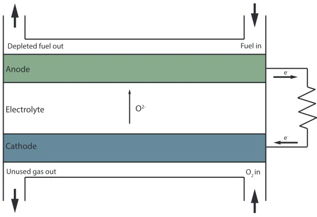
A SOFC consists of a cathode, separated from an anode by a solid electrolyte, and
the electrodes are connected to an external circuit, as shown in figure 1.1 [18]. The
cathode is often a mixed ionic and electronic conducting ceramic, which must have
good electronic conductivity and a high oxygen diffusion coefficient; the electrolyte is
a dense oxygen ion conducting ceramic with high ionic conductivity; and the anode
is often a metal-ceramic composite with suitable electronic conductivity and catalytic
good chemical compatibility with other components, good TEC match to avoid
crack-ing, stability under the SOFC operating conditions, high strength and, to make them
viable for widespread application, should have low cost [4].
Cathode Anode
Electrolyte
e
-e
-O2 in
Fuel in Depleted fuel out
O
[image:23.596.163.473.185.398.2]2-Unused gas out
Figure 1.1: Schematic of a solid oxide fuel cell
Oxide-based ceramics are used for the electrolyte, and include yttria stabilised zirconia
(YSZ), gadolium doped ceria (GDC), samarium doped ceria (SDC), and the perovskite
La1−xSrxGa1−yMgyO3−0.5(x+y) (x,y = 0.1–0.2) (LSGM). The anode is usually a porous
ceramic-metallic composite, often of the electrolyte material and NiO (e.g. NiO/YSZ,
NiO/GDC, NiO/SDC), which gives a TEC close to that of the other cell components.
At high temperatures, noble metals or electronically conducting oxides can be used for
the cathode, with insufficient long-term stability and high costs associated with noble
metals making them unsuitable for commercial applications. Electronically conducting
perovskite-based materials, such as Sr- or Ca-doped LaMnO3provide good performance
at high temperature, and excellent TEC match with electrolyte materials. At lower
op-erating temperatures, mixed ionic and electronic conducting perovskites are required,
with A- and B-site co-doped LaFeO3, LaCoO3 or LaMnO3, or layered perovskite-based
materials, such as Ruddlesden-Popper materials considered as potential cathode
metal alloys such as ferritic stainless steel, as they are stable under both oxidising and
reducing conditions.
At the cathode, oxygen from the air is reduced, generating oxide ions in the electrolyte,
according to the oxygen reduction reaction (ORR)
1
2O2(g) + 2e
−→
O2− (1.1)
The generated oxide ions are transported through the electrolyte to the anode, where
they react with the fuel, generating water (and CO2 where hydrocarbon fuels are used),
and releasing electrons to the external circuit, generating electrical power [5]. At the
anode, the (hydrogen) fuel reacts with the oxide ions according to
H2(g) + O2− →H2O + 2e− (1.2)
The ORR is often limited by poor ionic conductivity of the cathode to taking place at
three-phase boundaries (TPB), a narrow region, where air, electrode and electrolyte
meet (figure 1.2 (a)). In order to ensure the reaction is not restricted to the TPB,
mixed ionic and electronic conductors are ideally used as cathode materials, allowing
oxygen incorporation on the whole surface of the cathode [19] (figure 1.2 (b)). This
increases the region in which the ORR can take place, improving the performance of
the fuel cell. Options for improving the performance of SOFCs include optimising the
Cathode
Electrolyte TPB
O2
O
2-Oads
2e
-Oads MIEC Cathode
Electrolyte O
2-2e
-O
2-Oads O2
Figure 1.2: Schematic of a three-phase boundary in a solid oxide fuel cell showing
currently used materials for use at IT, or developing potential new materials for the
SOFC components.
1.3
Perovskite Oxides
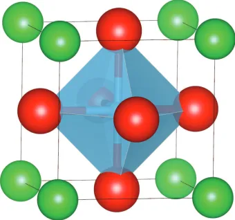
Perovskite oxides are a family of compounds with crystal structure related to that of
CaTiO3 [20]. The ideal perovskite structure, ABX3 (where A and B are cations, with a
combined charge of +6 (e.g. A1+and B5+, A2+ and B4+ or A3+ and B3+) and X is often
oxygen), has cubic symmetry, with space group Pm¯3m, and consists of 12-coordinate
[image:25.596.234.404.322.481.2]A ions and corner-sharing BX6 octahedra, as shown in figure 1.3.
Figure 1.3: Ideal cubic perovskite structure. A ions are shown in green, B ions are
shown in blue and X ions in red
Perovskite oxides can exhibit superconductivity, colossal magnetoresistance,
ferroelec-tricity, piezoelecferroelec-tricity, and optical transparency, depending on their composition [21–
26]. Materials with similar pseudocubic structures and matching lattice constants
can be synthesised, and they can exhibit both p- and n-type conductivity, and thus could be used to fabricate all-perovskite-oxide transparent electronics. They can
ac-commodate ionic substitution on both the A- and B-sites, carrier doping and oxygen
non-stoichiometry. Sb- and Nb-doped SrSnO3 thin films have shown high optical
trans-mittance, above 90%, and goodn-type conductivity, as well as good compatibility with other perovskite oxide thin films [27]. Recently, the transparent perovskite BaSnO3
(200–300 cm2V−1s−1), and conductivity (104 Scm−1), which is comparable with current
n-type TCOs such as In-doped SnO2 [26].
1.3.1
Goldschmidt tolerance factor
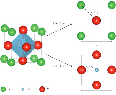
The cubic perovskite structure is uncommon, and the main factors responsible for its
distortion are strain effects (ionic radii), deviation from the ideal composition, and
Jahn-Teller effects, with a combination of these effects often observed [28]. In the
cubic cell, shown in figure 1.4, the lattice parameter, a, can be written in terms of the
ionic radii, rA, rB and rX, in the A-X and B-X planes.
A-X plane
B-X plane
r
A+rX
r
B+rX
A B X
a
[image:26.596.80.473.310.632.2]a
Figure 1.4: Goldschmidt tolerance factor in the cubic perovskite unit cell. The
lattice parametera is given in terms of the ionic radii in the A-X and B-X planes
Thus, the lattice parameter of the unit cell is given by
The ratio of these expressions for a is known as the Goldschmidt tolerance factor, t
[29], which allows estimation of the size mismatch and hence the degree of distortion
expected.
t= √(rA+rX)
2(rB+rX)
(1.4)
In the ideal case,t = 1, and values oft between 0.9 and∼1 give a cubic or pseudocubic structuree.g. SrTiO3(t= 1.00). Whent is greater than 1, due to either large A or small
B cation, the A cations do not fit into their interstices, and hexagonal or tetragonal
structures become more stable, e.g. BaNiO3-type structures (t = 1.13). If t <0.9, the
BX6 octahedra tilt to fill space (GdFeO3-type distortion), giving orthorhombic (figure
1.5 (a)) e.g. GdFeO3 (t = 0.89) [30], or rhombohedral (figure 1.5 (b)) structures. It
should be noted that the Goldschmidt tolerance factor is simply a tool which allows
rough estimation of the structure, and the crystal structure may differ from what is
predicted by this factor e.g. BaTiO3 (cubic, with t = 1.06), LaMnO3 (orthorhombic,
with t = 0.95) and LaAlO3 (rhombohedral, with t = 1.01).
In perovskite materials, distortion of the structure may also occur due to Jahn-Teller
effects. The Jahn-Teller character of cations at the B site, such as Mn3+ in LnMnO3
(Ln = La, Pr, Nb), or Mo5+ in the double perovskite Ba
2NdMoO6, leads to elongation
of the BO6 octahedra (figure 1.5 (c)). Jahn-Teller distortions occur when there are
degenerate d orbitals; the system undergoes distortion, lowering its symmetry and
energy, and removing the degeneracy [31]. Variation of the oxygen content can also
lead to deviation from the ideal structure. The presence of oxygen vacancies means
that there are incomplete octahedra within the structure, causing it to distort from
(a) (c)
[image:28.596.119.432.84.513.2](b) (d)
Figure 1.5: (a) Orthorhombic GdFeO3structure, showing octahedral rotations; (b)
rhombohedral LaAlO3; (c) tetragonal Ba2NdMoO6, showing elongated BO6 octahe-dra; (d) orthorhombic SrFeO2.5, showing oxygen vacancies and incomplete octahedra
1.4
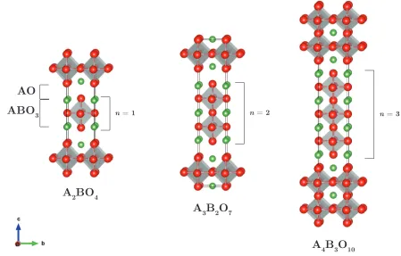
Ruddlesden-Popper oxides
Ruddlesden-Popper phases, An+1BnO3n+1, where A is a rare-earth or alkaline earth
and B is a transition metal, have shown promise as cathode materials for IT-SOFCs.
These materials consists ofn ABO3 perovskite layers separated by AO rocksalt layers,
shown in figure 1.6. They can accommodate either oxygen hypostoichiometry or
and electrical properties for use as SOFC cathodes. Oxygen hyperstoichiometry can
be achieved by incorporation of oxygen ions into interstitial sites in the rocksalt layers.
A
2BO4
A
3B2O7
A
4B3O10
n = 1 n = 2 n = 3
AO
ABO
[image:29.596.92.541.164.451.2]3
Figure 1.6: An+1BnO3n+1 Ruddlesden-Popper oxides, for n = 1–3, with A atoms
shown in green, B atoms sit at the centre of the grey octahedra and O atoms are shown in red
1.5
Cathode Materials for SOFCs
The main family of materials which has been investigated for the cathode of SOFCs is
the perovskite oxides, the structure of which is described in section 1.3. For high
tem-perature operation, La1−xSrxMnO3−δ(LSM) is used due to good electrical conductivity,
electrochemical activity for the ORR, high thermal stability, good TEC match with
common electrolyte materials (table 1.1), and good compatibility with the commonly
used electrolytes, such as YSZ, GDC and LSGM [18, 32–36]. In table 1.1, the
con-ductivity listed is the reported experimental electrical concon-ductivity in the temperature
Table 1.1: Thermal expansion coefficients, and experimentally measured
conduc-tivity for perovskite based cathodes and commonly used electrolyte materials
Cathode TEC (× 10−6 K−1) σ (S cm1) Ref.
LaMnO3 11.3–12.4 103 [37]
La1−xSrxMnO3−δ 12.0-13.7 120–202 [33, 34, 37]
∼10−7–10−4 (σ
i) [36, 38, 39]
La0.6Sr0.4CoO3−δ 21.3 1500–2500 [40]
La0.6Sr0.4Co0.2Fe0.8O3−δ 15.3 300–330 (σi); [41]
8 × 10⁻³ (σel)
Ba0.5Sr0.5Co0.8Fe0.2O3−δ ∼24.0 30–35 [42]
La2NiO4+δ 13.0 ∼50–60 [43]
Pr2NiO4+δ 13.6 ∼100–120 [43]
Nd2NiO4+δ 12.7 ∼30–40 [43]
GdBaCo2O5+δ 16.4 400–900 [44]
PrBaCo2O5+δ 24.6 ∼400–600 [45, 46]
LaCrO3 ∼8.5 0.2–0.35 [47, 48]
Electrolyte
GDC 13.5 ∼10−2 (σ
i) [35, 49, 50]
YSZ 10.8 ∼10−3–10−1 (σi) [35, 50]
LSGM 11.1 ∼10−2–10−1 (σ
i) [35, 50]
Other perovskite oxides have been examined as potential cathode materials for IT
operation, such as Sr-doped LaCoO3, which has shown good mixed ionic and electronic
conductivity, and good ORR activity [18, 35, 51]. In La1−xSrxCoO3−δ, the introduction
of Sr at low concentration (x <0.4) is charge compensated by a change in Co valence, with a maximum in Co4+ concentration at x = ≈0.4, while for higher concentration (x > 0.4), compensation is mainly by formation of oxygen vacancies. This results in improved catalytic activity and ionic conductivity of the cathode. However, Sr-doped
LaCoO3 reacts with YSZ at low temperature, forming insulating SrZrO3 and La2Zr2O7,
and has a very high TEC. The use of GDC or SDC electrolytes which are stable with
Sr-doped LaCrO3, or a barrier interlayer between cathode and electrolyte can address
phases. Composite cathode/electrolyte materials or doping at the Co site can reduce
the TEC to values closer to those of the electrolyte materials. When doped with Fe
at the Co site, (La1−xSrxCo1−yFeyO3−δ), it retains good catalytic activity, mixed ionic
and electronic conductivity, and has improved TEC and improved thermomechanical
stability compared to Sr-doped LaCoO3, but lower electronic conductivity in the IT
range (table 1.1) [40, 41, 52–55].
Perovskite oxides with alkaline-earth metals at the A-site have also been considered for
SOFC cathodes, e.g.Ba0.5Sr0.5Co0.8Fe0.2O3−δ (BSCF) [18]. BSCF has a very high bulk
oxygen transport rate due to its high vacancy concentration (δ >0.65). However, it has low thermal stability, a high TEC, and lattice instability, with Ba-rich compositions
lying at the border of the cubic perovskite stability [42, 56, 57]. ˇSvarcov´aet al.report a
phase transformation between the cubic phase and a mixture of the cubic and hexagonal
phases results in decreased electrical conductivity and slower oxygen transport, which
leads to performance degradation over time at low operating temperatures [57].
Layered double perovskites, AA’B2O5+δ, where A is a rare earth, A’ is an alkaline
earth (usually Ba), and B is a transition metal, have recently attracted attention as
potential SOFC cathode materials due to their good oxygen transport properties, high
electronic conductivity above 600 K, and fast oxygen surface exchange kinetics [18, 46,
51, 58]. GdBaCo2O5+δis one such material, which exhibits good chemical compatibility
with GDC and LSGM electrolytes, but reacts with YSZ at temperatures greater than
700°C, forming BaZrO3, and has a higher TEC than these electrolyte materials [44, 51,
59]. PrBaCo2O5+δ also shows very good oxygen transport properties and fast oxygen
surface exchange. However, it has a high activation energy for oxygen diffusion and a
very high TEC, so will mismatch with common electrolyte materials [45, 46].
Ruddlesden-Popper phases have also shown promise as cathode materials. The most
widely studied Ruddlesden-Popper materials are those in the n = 1 series, with A =
La, Nd and Pr and B = Ni. These materials show high diffusivity of oxygen interstitials
in the LaO layers, promising electrocatalytic properties and TECs which show a good
match to those of common electrolytes. They have lower electronic conductivity
series. They show improved ionic conductivity, good long-term stability, compatibility
with LSGM, and good electrode performance.
While perovskite-based materials are the most widely studied for SOFC cathode
appli-cations, non-perovskite-based materials have also been examined, such as pyrochlores
(Bi2Ru2O7, Pb2Ru2O7), which exhibit good ionic conductivity and high catalytic
ac-tivity for the ORR. However, due to issues with long-term stability with GDC
(degra-dation into Ru2O) or YSZ (e.g partial transformation of Bi2Ru2O7 into Bi3Ru3O11)
electrolytes and the high cost of Ru-based pyrochlores, they are unlikely to be suitable
for large-scale development [60, 61]. Bismuth oxides based on Bi4V2O11 Aurivillius
phases (BIMEVOX materials, BI = bismuth, ME = metal dopant, V = vanadium, OX
= oxygen) show good oxide ion conduction at reduced SOFC operating temperatures
[55, 62]. They have poor electronic conductivity so have been investigated in
com-posites with electronically conducting metals. These materials also have poor thermal
stability so may not exhibit the long-term stability required for commercial use.
1.5.1
Previous studies on LaMnO
3-based SOFC cathodes
Very little experimental work has been carried out on LaMnO3-based materials for use
in IT-SOFCs, with the main focus being on Sr-doped systems for high temperature
ap-plications [54]. Above 750 K, LaMnO3 is pseudocubic, and below this, it is
orthorhom-bic. The electronic conductivity of LaMnO3 may be enhanced by substitution of La3+
by divalent cations such as Ca2+, Sr2+ or Ba2+ [37, 63]. Sr is the most commonly
used dopant for LaMnO3-based cathodes, as Sr-doped LaMnO3 is stable and has high
electronic conductivity under the oxidising conditions at the cathode. The structure
of La1−xSrxMnO3−δ varies with the Sr content, with different works reporting different
crystal structures. The early work of Hammouche et al. found La1−xSrxMnO3−δ to
have a hexagonal-rhombohedral structure forx = 0.1–0.5 [64], while later works report
an orthorhombic structure for x ≤ 0.2, a monoclinic or hexagonal structure for 0 ≤ x ≤ 0.2, and a rhombohedral or tetragonal structure forx ≥ 0.5 [65–67].
The enhancement of the electronic conductivity is due to the formation of charge
(x ≤0.5), doping with Sr oxidises the Mn ion, effectively increasing the hole concentra-tion and improving the electrical conductivity [69–72]. In Kr¨oger-Vink notation, this
is given by
MnxMn+ SrO←−−−→LaMnO3 Sr0La+ MnMnr + OxO (1.5)
where MnxMn is a Mn(III) ion Sr0La is a Sr ion at a La site, MnMnr is a Mn(IV) ion and OxO is an oxygen ion in an oxygen site.
The TEC of LaMnO3 is reported to be in the range 11.3–12.4 × 10⁻⁶K−1, which
is higher than that of YSZ (10.8 × 10⁻⁶K−1) and lower than that of GDC (13.5 ×
10−6K−1), but in good agreement with that of LSGM (11.1 × 10⁻⁶K−1) [35]. When doped with Sr, the TEC increases, with values of 12.0–13.7× 10⁻⁶K−1 for increasing
Sr content [33, 34, 37], giving improved compatibility with GDC. The electronic
con-ductivity of La1−xSrxMnO3−δ (for 0 ≤ x ≤ 0.8) as a function of oxygen pressure and
temperature up to 1273 K has been investigated [72–74]. For lower Sr concentrations
(x ≤ 0.2), the conductivity was found to increase with temperature, while for higher Sr concentration (x ≥ 0.3) a decrease in conductivity with temperature was observed. This change in behaviour was attributed to a metal-insulator transition in Sr-doped
LaMnO3. Under oxygen-excess conditions (pO2 > 10
−5 bar), the conductivity was
found to remain constant, but decreased sharply under oxygen-deficient conditions.
Oxygen surface exchange and diffusion are important for the ORR at the cathode,
and by improving the ionic conductivity of the cathode, the active area for the ORR
may be increased. The magnitude of the diffusion coefficient in LaMnO3-based
mate-rials is low compared to other acceptor-doped LaBO3 (B = transition metal) due to a
low oxygen vacancy concentration, which limits the ionic conductivity in these
materi-als. Secondary ion mass spectrometry (SIMS) has been used to determine the oxygen
diffusion coefficient of La1−xSrxMnO3−δ, which was found to increase with increasing
Sr content for x = 0.35–0.5 at 1173 K (∼10−14–10−12 cm2s−1) [75], or with increas-ing temperature from 973–1273 K in La0.8Sr0.2MnO3 (∼10−16–10−12 cm2s−1) [76, 77].
coefficient (∼10−14–10−8 cm2s−1), but caused a decrease in the electronic
conductiv-ity [75]. Short circuit diffusion was observed by De Souza et al. in La0.8Sr0.2MnO3,
which was speculated to be fast oxygen diffusion along grain boundaries [76]. An 18O
exchange study, followed by SIMS, and numerical analysis of 18O depth profiles, by
Navickas et al. found the oxygen diffusion coefficient for grain boundaries to be three
orders of magnitude higher than for grains [78]. This indicates that grain boundary
transport of oxygen could enhance the performance of La1−xSrxMnO3−δ cathodes for
SOFCs. A range of ionic conductivities have been reported for Sr-doped LaMnO3 in
the temperature range 1073–1273 K, with values of∼10−7–10−4 S cm−1with increasing
Sr content [36, 38, 39]. The variation in reported ionic conductivity may be due to
differences in preparation methods and measurement of the samples. The low ionic
con-ductivity of Sr-doped LaMnO3 indicates that further doping or modification is required
for it to be suitable for use in IT operation. As the oxygen vacancy concentration is
not increased, at IT the ionic conductivity of La1−xSrxMnO3−δ is low and the reduction
of oxygen is limited to the TPB regions. Doping La1−xSrxMnO3−δ at the B site with
Mg or a transition metal cation such as Co, Fe or Ni can cause an increase in the
oxygen vacancy content which can improve the ionic conductivity and the performance
of LaMnO3-based materials for IT operation [79].
Composite cathode materials may offer improved ionic conductivity and a larger TPB,
and can provide reaction sites for the ORR across the surface of the cathode.
Compos-ites of La0.8Sr0.2MnO3/YSZ, with 30–40 wt.% LSM have been investigated [80, 81] to
determine their thermal stability and oxygen diffusion properties. At high temperature,
the oxygen diffusion coefficient of La0.8Sr0.2MnO3/YSZ composites is higher than that
of La0.8Sr0.2MnO3 but lower than that of YSZ, and ionic conductivities of 3–5 × 10⁻³
S cm−1 at 1173 K are reported. However, the thermal stabilities of the composites are
an issue at higher temperatures, with the reaction of La0.8Sr0.2MnO3 and YSZ forming
La2Zr2O7 and MnO, which can impede cathode performance [82].
One of the disadvantages of the use of LaMnO3-based materials as SOFC cathodes is
that they can readily react with other components of the fuel cell, such as the YSZ
between La1−xSrxMnO3 and YSZ electrolyte has been extensively studied [83–86]. The
reactivity of the cathode can be affected by the ratio of A- and B-site cations present,
which can either enhance or degrade the cathode performance [66]. When A/B ≤ 1, Mn3O4 is formed, which can improve performance. However, in A-site deficient
mate-rial, the Mn3+ reactivity is enhanced, which leads to greater Mn dissolution in YSZ.
When A/B > 1, La2O3 is formed, which has a negative impact on performance due
to low conductivity and poor stability of its hydrated phase La(OH)3. In addition,
La2O3 reacts with YSZ, forming the highly resistive La2Zr2O7 phase at the
bound-ary of cathode and electrolyte. In La1−xSrxMnO3−δ, a high Sr content can lead to
Sr depletion from the lattice and formation of the insulating phase SrZrO3, again
de-grading cathode performance. In contrast to YSZ, no reactivity is reported between
GDC and La1−xSrxMnO3−δ [87], and studies on the compatibility of LSGM found that
there is minimal diffusion of Mg and Ga into La1−xSrxMnO3−δ, even at high
tempera-ture [88, 89]. La1−xSrxMnO3−δ may also react with the interconnects, which are often
Cr-containing materials, such as stainless steel or LaCrO3-based materials. At high
temperature under oxidising conditions, volatile Cr-containing species are generated.
These species can interact with LaMnO3-based cathode materials, poisoning them and
reducing their performance [90–92].
Extensive theoretical studies have been carried out on both cubic and orthorhombic
bulk LaMnO3, further discussed in section 4.1. Density functional theory (DFT) and
DFT + U (discussed in sections 2.2.5 and 2.2.6) studies have been carried out to
in-vestigate the performance of the local density approximation (LDA) and generalised
gradient approximation (GGA) in the simulation of structure, electronic and magnetic
properties [93–96]. In these studies, both LDA and GGA (using Perdew-Wang-91
(PW91) and Perdew, Burke, and Ernzerhof (PBE) approximations) can reproduce the
volume to within 1% of the experimental values, but underestimate the Jahn-Teller and
GdFeO3 distortions, and the band gap of orthorhombic LaMnO3. Use of DFT + U,
which corrects for the self-interaction error by penalising delocalisation of electrons
(dis-cussed in section 2.2.6) improves the description of the electronic and magnetic
a +U correction to the Mn 3d states, the effect the application of a +U correction to
the O 2p states as well as the Mn 3d states has not previously been examined. Hybrid
DFT (discussed in section 2.2.7), using the Heyd, Scuseria and Ernzerhof (HSE06),
Becke, 3-parameter, Lee-Yang-Parr (B3LYP) and PBE0 functionals also provide an
improved description of electronic and magnetic structure of LaMnO3 compared to
standard DFT [97–100]. Previous theoretical studies of LaMnO3 surfaces, using DFT
and hybrid calculations, have focused mainly on the high-temperature phase [101–104],
and work on the orthorhombic phase has only focused on some of the low index surfaces
[105]. Further investigation is required to determine the stability of all the low index
surfaces of LaMnO3 and formation of defects at these surfaces.
In this thesis, the structural and electronic properties of LaMnO3 are examined, testing
the performance of PBE, PBE + U, PBEsol, PBEsol + U, and HSE06 functionals to
describe these properties. The low index surfaces of LaMnO3 are modelled using the
functional which best describes the bulk properties. In bulk LaMnO3 and at its low
index surfaces, the formation of oxygen vacancies is investigated, and in bulk LaMnO3
the energy barriers to oxygen migration are calculated. In addition, doping LaMnO3
with akaline earth metals is examined, to determine site selectivity and the charge
compensation mechanism for the dopants.
1.5.2
Previous La
2NiO
4+δstudies for SOFC cathodes
La2NiO4+δ(Ruddlesden-Popper phase withn = 1, as shown in figure 1.6) has attracted
attention as a cathode material for SOFCs as it can accommodate oxygen interstitial
ions in the LaO layers, centred in a tetrahedron of nearby La ions [106], providing a path
for oxygen diffusion [107]. Hybrid DFT calculations using B3LYP in CRYSTAL09 [108]
show rotation of the NiO6 octahedra away from the oxygen interstitial in orthorhombic
La2NiO4+δ(δ= 0.125), with the apical oxygen ions nearest the interstitial displaced
to-wards their Ni centres. Forδ= 0, La2NiO4 is reported to undergo two structural phase
transitions, with a low temperature tetragonal phase (space group P42/ncm) present
La2NiO4+δ based materials exhibit good electronic conductivity in the temperature
range 600–1100 K (10-110 S cm−1), higher ionic conductivity than perovskite-based
materials (∼10−2 S cm−1), good TEC match with electrolyte materials, and stability
at SOFC operating conditions [55, 62].
Oxygen diffusion in La2NiO4 has been examined by a number of groups, using SIMS to
examine oxygen tracer diffusion. Studies on La2NiO4+δ single crystal [43, 111],
poly-crystalline La2Ni1−xCoxO4+δ [112], and epitaxial films [113] find the oxygen diffusion
coefficient to be one to two orders of magnitude higher in the ab plane (LaO layers)
compared to along the perpendicular direction (c axis). Although there is limited
mo-bility in the perpendicular direction due to this anisotropy, the conductivity in theab
plane is high enough to give ionic conductivity suitable for mixed ionic and electronic
conducting cathodes.
The effect of introducing dopants to the La and Ni sites has also been investigated, with
alkaline-earth or rare-earth dopants introduced at the La site, and transition metals
such as Cu, Co or Fe at the Ni site. Substitution of Sr for La can increase the electronic
conductivity (up to ∼270 S cm−1) of La
2NiO4 and improve its stability, though the
TEC increases with Sr content to values greater than those of the electrolyte (up to 17
×10−6K for high Sr content), and causes a decrease in the oxygen diffusion coefficient
[43, 114].
The introduction of Co was found to have little effect on the oxygen diffusion coefficient
in La2Ni1−xCoxO4+δ for x ≤ 0.3, and higher diffusion coefficients were observed when
the Co content was high (x ≥0.5) [112]. The behaviour of crystal lattice deformation in La2NiO4-based materials due to interstitial oxygen has been investigated for 10% Fe-,
Co- and Cu-doped systems, in the temperature range 873–1173 K (high temperature
tetragonal structure), for oxygen partial pressure pO2 = 10
−24–1 bar [115]. Both
Fe-and Co-doped only exhibit oxygen-excess stoichiometry, while Cu-doped can exhibit
oxygen deficiency under lowpO2, which is also seen in Sr-doped La2NiO4 and La2CuO4. Previous studies on La2NiO4 and Nd2NiO4 showed that oxygen vacancies and oxygen
concentration is found to be dependent on dopant species, with Fe-doped showing the
highest hyperstoichiometry. Fe doped in La2NiO4 is trivalent according to M¨ossbauer
spectroscopy measurements, with a magnetic sextet observed at 4 K [118], with Fe
doping charge compensated according to
Fe2O3+Vi” →2Fe
r
Ni+ O ” i + 2O
X
O (1.6)
Oxygen transport in Sr- and Fe-doped La2NiO4 (La2−xSrxNi1−yFeyO4+δ, x = 0.5,y =
0.1–0.4 andx = 0.8,y = 0.1,0.2 and 0.4) has been examined for the high-temperature
tetragonal phase [119]. It was found that effect of Sr substitution on the oxygen
per-meation flux was dependent on the Fe content, with an increase in the oxygen flux
for low Fe content (y = 0.1), which was attributed to an increase in oxygen vacancy
concentration. For higher Fe content (y = 0.2–0.4), the oxygen overstoichiometry is
significantly higher than fory= 0.1, and doping with Sr led to a decrease in the oxygen
flux due to a decrease in the interstitial oxygen concentration. The highest oxygen
per-meation flux was obtained for La1.5Sr0.5Ni0.6Fe0.4O4+δ, which although it showed lower
ionic conductivity than undoped La2NiO4, the oxygen surface exchange, which has a
significant role in cathode performance, was improved, giving an overall improvement
in its properties for SOFC application.
Recent experimental work on the {110}and {001}surfaces of Sr-doped La2NiO4 using
low energy ion scattering (LEIS) have determined that Ni is not present at the
out-ermost surface layer, and using angle-resolved photoelectron spectroscopy near-surface
region of these terminations saw that the amount of Ni decreases as the surface is
ap-proached [120, 121]. This was supported by their study of the thermodynamic stability
of La2NiO4 [122]. A Ni-enriched layer was found a few nanometres below the surface.
This Ni-rich region is reported to be due to segregation of the La cations to the
sur-face, and partial decomposition at the surface of La2NiO4 into La2O3 Ni-rich n > 1
Ruddlesden-Popper phases.
The compatibility of La2NiO4 with GDC, YSZ and LSGM electrolytes has been
and YSZ at 973 and 1173 K, decomposing into higher order Ruddlesden-Popper phases
and insulating Zr-containing phases (YSZ electrolyte) which limits its suitability as
cathode material for SOFCs [123, 124]. However, it has been found to be stable with
LSGM electrolyte, with no evidence of formation of secondary phases after a period of
72 h at temperatures up to 1273 K.
Previous computational studies on La2NiO4 have been carried out on the orthorhombic
and tetragonal phases using DFT, DFT + U, hybrid-DFT and molecular dynamics
(MD), further discussed in section 6.1. The incorporation of oxide ions into the lattice,
oxide ion mobility, interaction of molecular oxygen and oxygen surface exchange have
been investigated using DFT and DFT + U calculations [108, 125–127]. MD has also
been used to investigate the oxygen transport in La2NiO4, to determine the diffusion
mechanism and determine the effect of oxygen content on the activation energy [128].
In their work, the low index surfaces have been examined using METADISE, with the
crystal morphology predicted, as well as the effect of doping with Fe or Cu at the Ni
site on the surface stability, and the compensation mechanism for doping with Sr on
the La site [129].
Orthorhombic La2NiO4 is investigated in this thesis, with the formation energy of
oxygen defects in the bulk and at its low index surfaces examined. The oxygen diffusion
mechanism for interstitial oxygen as investigated, considering paths within the rocksalt
layers and across the perovskite layers. In addition, the site selectivity and the charge
compensation mechanism for Sr and Fe doping is examined.
1.5.3
Previous studies on LaCrO
3for use in SOFCs
LaCrO3-based materials may be suitable as SOFC cathodes as they have good
elec-tronic conductivity and good chemical stability under SOFC operating conditions [130].
LaCrO3 has mainly been investigated as interconnects for high temperature SOFCs.
The TEC of LaCrO3 when undoped is 8.5 × 10⁻⁶K, which is significantly lower than
other components, but doping with Sr or Ca increases it to ∼10–11 × 10−6K, which is closer to that of YSZ [131–134]. Co-doping with Sr at the La site and Co or Mn at
the average ionic radius of the B-site cation, while doping with other transition metals
(Fe, Ni) did not have an observable effect [134].
LaCrO3-based materials have attracted attention as oxygen transport membranes for
applications in energy conversion, gas separation and syngas production (e.g. by
par-tial oxidation of coal, oil or natural gas) [48]. Doped LaCrO3 materials have excellent
thermochemical stability across a range of temperatures up to 1273 K, and oxygen
par-tial pressure from 10−20–0.21 atm. They exhibit predominantly electronic conductivity,
and undoped LaCrO3 has low ionic conductivity. The introduction of dopants at the
La and Cr sites of LaCrO3 may be used to obtain the desired thermal and electrical
properties. Sr and Ca are used as La site dopants, and are expected to improve the
electronic conductivity [135, 136]. The use of transition metal dopants on the Cr site
is to maintain the thermal and structural stability and to increase the oxygen vacancy
concentration. In the oxidising conditions of SOFC cathodes, substitution of La with
Ca or Sr will be charge compensated by hole formation. There is little experimental
work on Cr site doping, with Fe, Ni or Co doping reported to cause an increase in the
oxygen vacancy concentration of doped LaCrO3 [137].
Undoped LaCrO3 has a lower orthorhombic to rhombohedral phase transition
tem-perature (∼550 K) than other perovskite oxides used for SOFC cathodes, but the introduction of dopants can stabilise the structure at higher temperatures, depending
on dopants concentration and type. La0.75Sr0.25Cr0.5Mn0.5O3−δ when fired at 900°C for
120h [138], and LaCr0.8Fe0.2O3 and LaCr0.6Co0.2Fe0.2O3 calcined at 1123 K are stable
in the orthorhombic structure [139]. Both La1−xSrxCrO3 (x < 0.2), sintered at
tem-peratures from 1173–1873 K [133, 140, 141], and La0.8Sr0.2Cr0.8Mg0.2O3 at 1673 K [142]
were also found to have orthorhombic structure.
In this thesis, the ionic and electronic conductivity of LaCrO3 is investigated for
ap-plication in SOFC cathodes. The formation of intrinsic and Sr defects in LaCrO3 is
investigated, to determine the origin of charge carriers in LaCrO3. The formation
en-ergies and barriers to migration of oxygen vacancies in bulk LaCrO3 were calculated
1.6
Oxygen diffusion in perovskite-based materials
Oxygen vacancies are the dominant oxygen defect in ABO3 perovskite-based materials,
with diffusion occurring via migration of the vacancies. In this mechanism, the atoms
move from a lattice site into a neighbouring vacancy, which allows migration of oxygen
through the crystal, as shown in figure 1.7 (a) [143]. In materials which can
accommo-date interstitial oxygen, such as Ruddlesen-Popper phases in their rocksalt layers, there
are two possible diffusion mechanisms for the interstitial oxygen. The simplest
mech-anism of diffusion of interstitials is that where an interstitial migrates directly from
one interstitial site to the next, shown in figure 1.7 (b). This mechanism is known as
interstitial diffusion. The second mechanism is one where interstitial atoms migrate via
a neighbouring lattice site, known as interstitialcy diffusion. The interstitial displaces
an atom from a lattice site to the next interstitial site. This mechanism can occur via
collinear interstitialcy diffusion, where the path is straight, shown in figure 1.7 (c), or
via non-collinear diffusion, shown in figure 1.7 (d).
Lattice site
Vacancy
Interstitial
Displaced atom (a)
(d)
(b)
[image:41.596.123.507.438.673.2](c)
Figure 1.7: Diffusion mechanisms for oxygen ions in perovskites and
1.7
Thesis outline
The flexibility of SOFCs and their potential for high efficiency fuel conversion has made
them an attractive technology for electricity generation. However, the high costs and
performance degradation associated with operation at high temperatures (> 1000 K) has driven research to investigate materials suitable for lower temperature operation.
The work presented in this thesis has been motivated by the need to develop suitable
cathodes for lower temperature operation of SOFCs. Chapter 1 has introduced fuel
cells, with a focus on SOFCs and the materials used for the cathode. The materials
which are of interest in this thesis are introduced, with background on their application
in SOFCs.
Chapter 2 covers the computational theory behind the methods used in thesis, outlining
the theory of electronic structure methods. Chapter 3 focuses on the implementation of
these methods within the Vienna ab initio simulation package (VASP). This includes
an overview of the methods used to gain insight into the geometric and electronic
properties of the materials under investigation.
In Chapter 4, the structural and electronic properties of LaMnO3 are examined.
Analy-sis of the performance of PBE, PBE +U, PBEsol, PBEsol +U, and HSE06 functionals
to describe these properties is carried out. From this investigation, a suitable functional
is chosen to simulate the low index surfaces of LaMnO3. Chapter 5 examines defect
formation in LaMnO3. The formation of oxygen vacancies in bulk LaMnO3 and at its
low index surfaces is investigated, and the energy barriers to oxygen migration in bulk
LaMnO3 are determined. In addition, the site selectivity and charge compensation
mechanisms for alkaline earth defect formation in LaMnO3 are examined.
The Ruddlesden-Popper oxide La2NiO4 is investigated in Chapter 6, with
determina-tion of the formadetermina-tion energy of oxygen defects in the bulk and at its low index surfaces.
As La2NiO4 can accommodate oxygen vacancies in the perovskite layers and oxygen
interstitials in the rocksalt layers, both are simulated in the bulk and at the surfaces
for interstitial oxygen as investigated, considering paths within the rocksalt layers and
across the perovskite layers.
In Chapter 7, LaCrO3 is investigated as a potential mixed ionic and electronic
con-ductor for SOFC cathode applications. The origin of charge carriers in LaCrO3 is
investigated, considering intrinsic defects and Sr defects, and calculating the
thermo-dynamic transition levels. In addition, the formation and migration of oxygen vacancies
in the bulk material was investigated.
Finally, in Chapter 8, the findings presented in this thesis are summarised. This is
followed by an outline of possible future work in the investigation of these materials
Computational Theory
Computational chemistry methods allow us to examine the properties of a wide range of
materials, to rationalise experimental observations, gain information about properties
which cannot be measured experimentally, and predict structural and electronic
prop-erties of materials which have not yet been synthesised. A range of theoretical methods
are available, and it is important to employ a suitable approach for the system size,
properties being calculated, and level of accuracy required. Classical methods, which
use force fields to model interactions between atoms, can calculate large systems in
a relatively short period of time but do not explicitly consider electrons. Quantum
mechanical methods can be used to determine the electronic structure of materials,
but are more computationally expensive.
In this chapter, quantum chemistry is discussed, along with some widely used quantum
chemistry methods. These methods include Hartree-Fock (HF), density functional
theory (DFT), and hybrid-DFT, and their advantages and disadvantages are addressed.
The application of the DFT-based methods used in this work is then outlined.
2.1
Quantum chemistry
2.1.1
The Schr¨
odinger Equation
The aim of quantum chemical calculations is the approximate solution of the Schr¨odinger
equation, which in its time-independent form is
ˆ
HΨ = EΨ (2.1)