Abstract— Modular detecting device to find the direction to
the source of γ-radiation is considered. The proposed device may be used for detection of radiation from the source and the search of direction to the source(s). The task becomes more actual due to rising demands for radiation safety and the need for a device by which a single measurement the direction of the source of danger (a γ source) can be found. The principle of work of a modular detecting device is the simultaneous operation of several detecting modules with anisotropic sensitivity to gamma radiation. It is shown that the system consisting of 4-8 modules can find the direction to the 106 Bq source of 137Cs which is located at a distance up to 100cm with an error of no more than 1-20.The results of the experimental study of the modular detection devices consisting of 4 and 6 modules scintillation (NaTl) detectors are presented. Simulation results agree with experimentally received ones.
Index Terms— direction to the source, scintillators, point
sources of radiation detection.
I. INTRODUCTION
U
NCONTROLLED sources of ionizing radiation represent a great danger to human health. There is a need in the detection, localization and monitoring of areas with the radioactive pollution. The elimination of any hot radioactive spots may be carried out only after pinpointing the location of the radiation source(s). Therefore, the problem of accelerated examination areas contaminated with γ-emitting radionuclide and find localization of γ -radiation sources, as well as development of methods for determining the direction to the γ -radiation source is of particular relevance. An extremely important task is the detection of illicit transportation of radioactive materials and the inspection of suspicious goods at the checkpoints. The most general case of detection of radioactive substances is the detection of point and limited size -artificial sources, and nuclear materials with γ and neutron radiation. Usually measured point sources and limited size sources have linear sizes that are significantly less than the distances between Manuscript received November 21, 2015; revised December 25, 2015. Elena V. Ryabeva is with the National Research Nuclear University MEPhI (Moscow Engineering Physics Institute), Kashirskoe highway 31, Moscow, RF, corresponding author, phone: +7-916-697-88-54; e-mail: [email protected].Vladimir V. Kadilin is with the National Research Nuclear University MEPhI (Moscow Engineering Physics Institute), Kashirskoe highway 31, Moscow, RF, e-mail: [email protected]
Grigory L. Dedenko is with the National Research Nuclear University MEPhI (Moscow Engineering Physics Institute), Kashirskoe highway 31, Moscow, RF, e-mail: [email protected].
detecting device and radiation source, and it is possible to consider limited size source as point source. The proposed modular detecting devices equipped with scintillation detectors may be applied to find direction to the small size sources (point sources).
II. BRIEF OVERVIEW OF AVAILABLE TECHNOLOGIES Depending on the type of problem being solved systems with anisotropic sensitivity may have different configurations and equipped with various recording devices. To determine the direction of the source a variety of technologies are traditionally used. In [1] collimated detector with an angular resolution of ~ 150, suitable for the detection of radioisotopes from the 241Am to 60Co is described. The advantages of the telescopic equipment are 1) high accuracy in determining the direction on conditions that small amount of particles are detected and 2)the possibility of constructing the angular distribution of γ-radiation fluxes from many sources; the disadvantages are 1) low detection efficiency, 2)limited aperture, 3) substantial weight and size of the equipment, 4) the necessity for a large number of measurements in the study of the angular distribution of radiation flux, 5) the necessity for a rotation of detector for determination of the angular distribution.
In [2] a device consisting of an array of semiconductor detectors is described. Blocks of semiconductor detectors are collected and separated by the layers of absorbing material. Type of semiconductor and absorbing materials is depended on what kind of radiation is to be measured. Analysis of the ratio of the number of events in each of the separated detectors allows determining the direction of the source.
In [3] a rotating detector for the control of remote point sources of gamma and neutron radiation is described. The system is developed to detect the source of radiation. Simulation results show that the proposed technique can detect during about 20 minutes and in an area of 100 m in diameter, a 1 mCi gamma ray source, with 90% sensitivity and false alarm probability of 0.1/hour.
In [4] the robot equipped with a single high resolution scintillation detector to quickly survey an area and transmit information about local sources of gamma radiation to a remote operator is described. The result is achieved by surrounding the detector with a lead sheath that blocks all gamma-rays except rays that incident along the detector's axial direction. A 180° horizontal scan is performed by rotating the detector. The directional profile of gamma radiation is constructed
Modular Detecting Device to Find Direction to
the Gamma-Ray Source
III. THE OBJECTIVES OF DEVELOPMENT A MODULAR DETECTING DEVICE
This paper discusses options for a modular detecting
device with different shapes and materials of the shield and a different number of modules to find the direction to the source of gamma radiation. Finding and localization of limited size sources of ionizing radiation with modular detecting device can be carried out with significant speedup of the examination of a the specified area because of the there is no need to implement numbers of measurements. To find the gradient of the gamma radiation field on the plane, it is enough to carry out a single measurement using modular detecting system. To determine the position of a point radiation source is necessary to conduct measurements in two different locations or simultaneous measurement with two mutually spaced modular detecting devises. The use of two modular detecting devices located on opposite sides of the target area, allows locating the source of the radiation, hidden in a large volume (containers, rail cars, trucks). Such a system could be complement for the stationary portal monitors used at the customs and other checkpoints.
IV. THE GENERAL DESIGN OF MODULAR DETECTING DEVICES The device consists of several modules of detectors (in this case - the scintillators), buried in the material of the screen. The screen acts as an absorber of gamma rays and thus forms an anisotropic sensitivity of each detecting module to
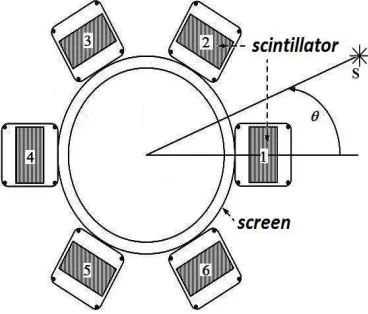
γ-quanta coming from different angles. The general scheme of construction of device is described in [5]. Figure 1 shows a general scheme - a horizontal section for modular detecting device consisting of 6 modules
Firstly it is necessary to determine order of numbering of modules to choose some reference line and agree that the task of determining the direction of the source is the problem of determination of the angle between the direction to the source and this references line. For example, here in the article the angle θ between the direction to the source and the direction to the selected (module 1) module is used (see figure 1). The numbering of the detecting units (module) is generally voluntary, because all of them are equivalent.
V. DETECTING DEVICE WITH FOUR MODULES.
The simplest model of a multi-detecting device consists of four scintillation (NaI (Tl)) blocks located in the same plane and separated by a screen (for example made of aluminum, which is equal to the radius of 7.7 cm). Simulation is performed with the source of 137Cs with activity 106 Bq and located at the distance of 100cm between the source and the detector. To investigate the dependence of count rates in the module on direction to the source the movement of point source located at a distance of 100 cm from the detector was simulated. The source was moved round a circle with R=100 cm, (the center is detecting device) in increment of 100. The dependence of the ratio of the number of photons detected by one module to the total number of photons detected by all modules together (relative count rate) N(θ) on the direction to the source of γ-radiation (angle θ) can be approximately expressed by the following function (for single source )
0 1 2 3
360 360 360
( ) cos cos 2 cos 3 j
j xc j xc j xc
k k k
N a p p p p
wc wc wc
θ θ θ
θ
− ⋅ − − ⋅ − − ⋅ −
= ⋅ + + ⋅ + ⋅
(*)
where, k - the number of modules, j – the number assigned to the module, xc - shift of the peak, wc - translating into radian measure, a - the factor, which is equal 1 for unfolding the angular position of a single source, and for unfolding in case of two sources - a power ratio of two sources (the equation itself has a somewhat different view). The dependence N(θ) is simulated with GEANT4 and plot is shown in the figure 2. The coefficients p0, p1, p2, p3 in
[image:2.595.47.231.100.257.2]equation (*) are estimated on stage of the device pre-calibration (Figure. 2).
Figure 1. General design of modular detecting device. The numbering of modules (assignment of 1,2,3,-6 for modules) is voluntary
.
[image:2.595.320.534.458.625.2]For parameters estimation the method for solving equations of MathCad [6] is used.
VI. DIRECTION TO SINGLE SOURCE FINDING BY A MODULAR DETECTING DEVICE
The task of finding the direction to the source or sources of the radiation by proposed device firstly is solved for the simplest case of single source. As a result of one measurement there are four count rates recording (one record for one module of device). The equation (*) is solved with respect to θ for each module separately. The two
directions to the source for each module will be results of this solution. The ambiguity is associated with the symmetry of the calibration curve relative to 1800. The imaginary direction to the source is discarded. The angle (direction to the source) is determined as an average of the four true values of θ. For the aim of simulation the source is located in the angle of 550. Mathematical simulation and obtaining the relative responses (count rates) of the detector modules at a measurement time of 1 minute was carried out. For visualization values of the count rates are put on the calibration curves for every module (Figure 3). Estimation of the angle of source is θ=540±20. The error in determining the angle is equal to 2°. Four modules device finds the direction to the 106 Bq source of radiation in the area of 100 cm with an error 20. The procedure for finding the direction of the source to a modular detection device for device with 6 and 8 modules was repeated. The results are shown in the table. 1.
VII. FINDING THE DIRECTION TO TWO SOURCES To find the direction to sources it is necessary to determine two angles from which radiation comes from and the ratio of the activities of two sources. To restore these three parameters the function for fitting the least squares package MathCAD - genfit was used.
The simulation for the two sources with a ratio of activity of the first source to the second source activity equal to 0.3, which are equidistant from modular device and radiating from the angles 250 and 550 respectively were made.
The parameters were estimated with the four modules device: the estimated activity ratio is 0.3, the angular position of sources – 25±20 and 54±20. The estimation is in agreement with simulated values.
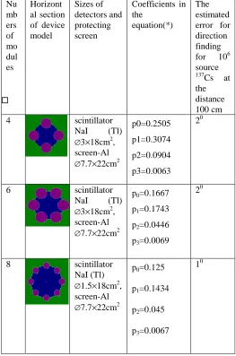
TABLEI
THE RESULTS OF SIMULATING ERROR IN FINDING THE DIRECTION TO THE SOURCE FOR DEVICES WITH A VARIOUS NUMBER OF MODULES
Nu mb ers of mo dul es
Horizont al section of device model
Sizes of detectors and protecting screen
Coefficients in the
equation(*)
The estimated error for direction finding for 106 source
137
Cs at the distance 100 cm
4 scintillator
NaI (Tl) ∅3×18cm2,
screen-Al ∅7.7×22cm2
p0=0.2505 p1=0.3074 p2=0.0904 p3=0.0063
20
6 scintillator
NaI (Tl) ∅3×18cm2,
screen-Al ∅7.7×22cm2
p0=0.1667
p1=0.1743
p2=0.0446
p3=0.0069
20
8 scintillator
NaI (Tl) ∅1.5×18cm2
, screen-Al ∅7.7×22cm2
p0=0.125
p1=0.1434
p2=0.045
p3=0.0067
10
VIII. EXPERIMENTAL STUDY OF MODULAR DETECTING DEVICE
The experimental studies of modular device characteristics were implemented with scintillation detectors based on single crystals of CsI (Tl) of rectangular cross section. To improve the energy resolution, for example, LaBr3 can be
used. The scintillator has been manufactured by the Kharkov Institute for Single Crystals, Ukraine. Detectors based on Figure 3 The simulated the relative count rates of the
[image:3.595.298.561.180.577.2] [image:3.595.49.279.199.398.2]said scintillators were produced in NRNU MEPhI.
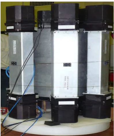
Sensitive elements of each module is a single crystal of CsI (Tl). Mono crystal is a cuboid with sizes 38cm×8cm ×4.5cm, enclosed in an aluminum casing (shell). On the front sides are flanges for mounting the PMT. Appearance four modules detecting device is shown in figure 4.
The source of 137Cs from the OSGI set with a yield of 11.35 kBq was used at the time of measurement 1 minute. Changing the angle position by turning the modular device around its axis was implemented.
In model experiments modular device was equipped with different types of cylindrical protecting screen: lead screen with external diameter 24 cm, thickness 1.8cm height 19 cm and the composite screen composed of an aluminum cylinder having an outer diameter d1 =8.25cm and thickness 0.2 cm plus lead cylinder with an outer diameter d2 = 9.25 cm, thickness 1 cm, height 37 cm. The screen from the material having an average Z is used also. It is widely used in building construction asbestos-cement pipe, a height of 40 cm external diameter of 33cm and a thickness of 2 and 7cm (see figure 4). No screens are specifically manufactured. Signal processing diagram from one module is shown in Figure 5. The gamma radiation from the source 1 enters the scintillation detector 2. The light flashes in the scintillator are recorded by two PMTs (FEU-185) 3.4, after which the signals from the preamplifier 5 and 6 fall into the adder 7. Then the signal is come to the analyzer 8 (ADC Ltd. "PARSEK") and the oscilloscope 9 (Tektronix- TDS 220). Pulse analyzer is combined with computer for analysis of the amplitude distributions. For the analysis of amplitude distributions high-speed 4k-USB spectrometric ADC "PARSEK" accumulating spectrometric information with the intensity up to 106 pulses per second is used. Oscilloscope type Tektronix- TDS 220 is used for visual control signals from the detector and control the frequency of incoming pulses to the input of the analyzer. A point source of gamma
137
Cs (1) is located at a distance of 100 cm from the central axis of modular device. Measurements are carried out for 1 minute.
IX. THE RESULTS OF THE EXPERIMENT AND SPECTROMETRIC ANALYSIS.
Either the full number of pulses or the sum of the number of pulses at the total absorption peak with known characteristics can be used when signal processing scintillators. The experiments of measurements of the apparatus spectrum for 137Cs source for various angular positions were carried out. Figure 6 shows the apparatus spectrum for 137Cs source for the position θ=30°. Spectra for rest source positions have the similar view. Subsequently, the sum of the number of pulses in the total absorption peak from 90 to 120 channel of pulse analyzer or the total number of received signals are used as the experimental data.
[image:4.595.46.244.43.279.2]Figure. 6. Instrumental spectrum of gamma rays from 137Cs source registered by module 1 (θ=30°). N1-count rate in the module 1.
Figure 4. Experimental four modules detecting device
[image:4.595.326.540.55.194.2] [image:4.595.323.536.484.672.2]X. EXPERIMENTS WITH 6 AND 4 MODULAR DEVICE WITH VARIOUS SCREENS.
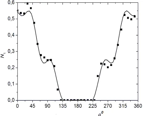
For all the screens used are obtained depending on the total (relative) count rate and count rate at the peak of total absorption on the angle of the source. Type of the experimental dependence of the count rate of pulses from the direction of the source can be modeled by expression (*) as was shown in the simulation of a multi-module device.
The results of experimental measurements for rectangular modules are shown in Figure 7. Measurement errors are small for the scale of the drawing. Curve is simulated module response to the source. A some deviation from form the previous simulated model (Figure 2) is due to the fact that the cross section scintillators in the experiment has a rectangular form, scintillators are not recessed into the protecting screen. The self-shielding effect by scintillators is observed also. The experiments and calculations are made with using a lead screen with a diameter of 24cm and a thickness of 1.8cm. The data presented in Figure 6 shows that the simulation results agree well with the experimental data.
XI. CONCLUSION
Conducted simulations and experimental studies have confirmed the possibility of using the proposed construction of a modular detecting device with anisotropic sensitivity of modules for finding the direction of the source of gamma-radiation.
Direction to one source of radiation is estimated by using the modular detecting device with four or six modules with an errors ±2°. If modular device has 8 modules, the direction of the source is estimated with an error of ± 1°. It is possible to determine the direction to two or more sources of radiation (shown through modeling) with the proposed modular device. Experimental research on the simplest physical model of the device confirmed the simulated angular dependence of the sensitivity of the module that allows making a statement about the suitability of the proposed model for the finding of direction to the source.
REFERENCES
[1] Kenneth L. Matthews II ; Blair M. Smith ; Adam W. Lackie ; William H. Hill, Jr. ; Wei-Hsung Wang ; Michael L. Cherry, “An electronically-collimated portable gamma-ray detector for locating environmental radiation sources”, in Proc. SPIE 6319, Hard X-Ray
and Gamma-Ray Detector Physics and Penetrating Radiation Systems VIII, 63190H, 2006.
[2] Uher, J. ; Frojdh, C. ; Jakubek, J. ; Pospisil, S., “Directional radiation detector”, in Nuclear Science Symposium Conference Record, NSS
'07. IEEE (Volume:2), 2007, рр. 1162 – 1165
[3] Jeffrey L. Lacy, , Athanasios Athanasiades, Christopher S. Martin, Liang Sun, , Jeffry W. Anderson, Tom D. Lyons, “Long Range Neutron-Gamma Point Source Detection and ImagingUsingUnique Rotating Detector”, in IEEE Nuclear Science Symposium
Conference Record N10-5, 2007, pp. 185-191.
[4] A. Miller, R.Marchrafi, A. Mohany, “Development of a semi-autonomous directional and spectroscopic radiation detection mobile platform”, in Radiation Measurements, V.72, 2015, pp. 53-59. [5] Ryabeva E.V., Kadilin V.V, Isakov S.B. et al ”Types of modular
detecting devices and methods of point gamma-radiation sources finding”, , in Nuclear measurement and information technology, № 3 pp. 49-62.
[6] E. Makarov. Engineering calculations MathCad15, Peter, 2011.
Figure. 7. Dependence of the count rate of the fist modular (N1) on the angle θ (direction to the source) for device with
[image:5.595.46.278.152.341.2]