Low-Complexity Erasure Insertion in Frequency-Hopping Spread-Spectrum Communications
Subjected to Fading and Partial-Band Interference
Lie-Liang Yang and Lajos Hanzo
Dept. of ECS, University of Southampton, SO17 1BJ, UK.
Tel: +44-703-593 125, Fax: +44-703-594 508
Email:
[email protected] and [email protected]
http://www-mobile.ecs.soton.ac.uk
ABSTRACT
In this paper we propose two novel low-complexity, low-delay era-sure insertion schemes, namely the Output Threshold Test (OTT) and joint Maximum Output and Ratio Threshold Test (MO-RTT). The employment of the OTT and MO-RTT is beneficial in the context of the ‘Errors-And-Erasures (EAE)’ Reed-Solomon (RS) decoding in a Slow Frequency-Hopping based Spread-Spectrum (SFH/SS) system usingM-ary Frequency-Shift Keying (MFSK). The statistics of the erasure insertion related decision variables associated with the OTT, MO-RTT as well as with the Ratio Thres-hold Test (RTT) are investigated, when the channel of each FH slot is modeled as flat Nakagami-mfading. The transmitted sig-nals also experience both Additive White Gaussian Noise (AWGN) as well as Partial-Band Gaussian Interference (PBGI). The per-formance of the proposed erasure insertion schemes and that of the erasure insertion scheme using the RTT is investigated and compared in the context of RS coded SFH/SS systems using MFSK modulation.
1. INTRODUCTION
In Slow Frequency-Hopping Spread-Spectrum (SFH/SS) wireless sys-tems Forward Error-Correction (FEC) codes, such as for example Reed-Solomon (RS) codes are often used, in order to mitigate the performance degradation due to background noise, intentional and unintentional interference as well as due to channel fading [1, 2]. In the context of RS coded SFH/SS systems using MFSK modula-tion, ‘Errors-And-Erasures (EAE)’ decoding is preferable to ‘Error-Correction-Only (ECO)’ decoding, since EAE decoding can typically achieve a significantly lower codeword decoding error probability, than ECO decoding, provided that a reliable erasure insertion scheme is invoked. In recent years the performance of RS coded SFH/SS sys-tems using EAE decoding based on erasure insertion schemes, such as the Ratio Threshold Test (RTT) [3] or the Bayesian approach [4], has received wide attention.
In this contribution two novel erasure insertion schemes, namely the Output Threshold Test (OTT) and joint Maximum Output and Ra-tio Threshold Test (MO-RTT), which have similar complexity to the classic RTT [3] are proposed for employment in RS coded SFH/SS systems using MFSK modulation. Their performance as well as the performance of the RTT is investigated, when the channel is modeled
This work has been funded in the framework of the IST project IST-1999-12070 TRUST, which is partly funded by the European Union. The authors would like to acknowledge the contributions of their colleagues.
as a flat Nakagami-mfading medium [5] and the transmitted signals are also exposed to Patial Band Gaussian Interference (PBGI) [1, 2]. We derive the exact Probability Density Functions (PDF) of the de-cision variables used for making erasure insertion dede-cisions associ-ated with the OTT, RTT and the MO-RTT erasure insertion schemes over flat Nakagami-mfading channels, under both the hypotheses that theM-ary demodulated symbol is correct (H1) and incorrect (H0). These PDFs are then used for investigating the characteristics of the OTT, RTT as well as MO-RTT over the above-mentioned
Nakagami-mfading channels. The performance of the RS coded SFH/SS system using MFSK modulation assisted by EAE decoding employing the OTT, RTT and MO-RTT is estimated and also compared with each other.
2. SYSTEM OVERVIEW
The system under consideration was described in [1, 2], and the reader might like to consult these references for their description. In the sys-tem considered SFH/SS using MFSK modulation, noncoherent de-modulation based on square-law detection, and an extended RS(N, K) code over GF(2b) are employed. We assume thatM =N = 2b≥4, so that eachb-bit RS code symbol describes anM-ary MFSK symbol. With the aid of SFH spreading and MFSK modulation, the transmitted signal can be expressed as
s(t) =√2PsRc
∞
X
n=−∞ ∞
X
i=−∞
PTc(t−nTc)PTs(t−iTs)
·cos [2π(fn+fi)t+ϕn+ϕi], (1)
wherePsis the transmitted symbol’s power without FEC,Rcis the
coding rate,PTc(t)andPTs(t)are unit pulses of durationTcandTs,
respectively, whileTcandTs are the FH dwell interval and MFSK
symbol duration, respectively. We assume thatLMFSK/RS symbols are transmitted in each FH dwell interval, i.e.,Tc =LTs.
Further-more, in Equation (1)fn is the hopping frequency during thenth
hopping interval,fiis theith tone frequency associated with theith
transmitted MFSK/RS data symbol. Finally,ϕnandϕiare random
phases during thenth FH interval and theith symbol interval. The FH patterns are modeled as sequences of independent ran-dom variables, each of which is uniformly distributed over the set of legitimate FH frequencies. For each FH tone, the channel is modeled as a frequency non-selective fading process obeying Nakagami-m
(AWGN). The PBGI occupies a fractionρ ≤1of the band, and the power spectral density of this contaminating source isNI/2ρ. The
AWGN is included in the analysis for modeling the receiver’s thermal noise, and it has a uniform spectral density ofN0/2. Thus, in the por-tion of the frequency band contaminated by PBGI, the total two-sided power spectral density of the noise isNn/2 = NI/2ρ+N0/2. In the remainder of the band, the total noise power spectral density is
Nn/2 =N0/2.
The demodulator consists of a bank ofM parallel noncoherent square-law detectors [6]. The detectors are followed by a decision device that employs a threshold test. The decision whether to erase a low-confidence symbol or not is made independently for each RS coded MFSK symbol. For those MFSK/RS symbols that are not erased, standard hard-decision demodulation is employed. The de-cision device is followed by anM-ary symbol deinterleaver and a decoder that employs EAE based RS decoding.
3. STATISTICS OF THE ERASURE INSERTION RELATED VARIABLES
In this section, various erasure insertion schemes using the OTT, RTT and the joint MO-RTT are investigated and the PDFs of the quantities involved in these erasure insertion schemes are derived. From these PDFs, we can gain an explicit insight into the properties of the re-lated erasure insertion schemes. Furthermore, with the aid of these PDFs, the corresponding RS codeword decoding error probability us-ing EAE decodus-ing can be estimated usus-ing a numerical approach.
Let H1 and H0 represent the hypotheses of correct decisions and erroneous decisions, respectively, concerning anM-ary symbol in the MFSK demodulator using hard-detection. Furthermore, let
PNn(H1)andPNn(H0)be the average correct and erroneous sym-bol probabilities, respectively, for a given value ofNn. Then, we have PNn(H1) = 1−PNn(H0), andPNn(H0)is given by
PNn(H0) = 1−
∞
X
k=0
M−1 X
n=0
(−1)k+n(1−m)k
k!
M−1
n
!
·
m m+γc
m
γc m+γc
−1
γc mn+nγc+m
k+1
, (2)
wheremis the fading factor associated with the Nakagami-mfading channels,γc=RcΩEs/Nn=RcΩbEb/Nn,Es=PsTsrepresents
the transmitted energy per symbol without FEC,b = log2M repre-sents the number of bits per MFSK/RS symbol, and finally, we have
Nn = N0+NI/ρwith a probability ofρ, whileNn = N0 holds with a probability of(1−ρ).
Let{U1, U2, . . . , UM}represent the decision variables input to
the MFSK demodulator of Fig.1 in [2]. We denote the maximum and the ‘second’ maximum of{U1, U2, . . . , UM}by
Y1= max
1 {U1, U2, . . . , UM}, (3)
Y2= max
2 {U1, U2, . . . , UM}. (4) In the context of the OTT, the decision variable subjected to an era-sure insertion isY1, i.e., the actual demodulator output is observed. In order to analyze the properties of the OTT-based erasure insertion scheme and to estimate its corresponding EAE RS decoding perfor-mance, the PDFsfY1(y|H1)andfY1(y|H0), given that the associated demodulated symbol is correct (H1) and incorrect (H0), respectively, must be derived.
The ratio involved in Viterbi’s RTT is defined as the ratio of the maximum to the ‘second’ maximum [3], or equivalently, it can be de-fined as the ratio of the ‘second’ maximum to the maximum, which can be expressed asλ=Y2/Y1, 0≤λ≤1.Similarly, in order to analyze the EAE RS decoding performance in terms of the RTT, the PDFs offλ(r|H1)andfλ(r|H0), given that the associated demodu-lated symbol is correct (H1) and incorrect (H0) are required.
Finally, in the context of the joint MO-RTT, the erasure insertion is based on the observation of both the maximumY1of (3) and the ratioλ = Y2/Y1. Hence, the joint two-dimensional (2D) PDFs of
fY1,λ(y, r|H1)andfY1,λ(y, r|H0)are required, in order to estimate the EAE RS decoding performance in terms of the joint MO-RTT erasure insertion scheme. Note that, bothfY1(y|Hϑ)andfλ(r|Hϑ) constitute the ‘marginal’ PDFs of the joint PDF offY1,λ(y, r|Hϑ) associated withϑ∈ {0,1}. Hence, their corresponding PDFs can be derived from the joint PDFs offY1,λ(y, r|Hϑ)in terms of the MO-RTT.
The joint PDFs ofY1andλunder the hypothesesH1of correction decision andH0of erroneous decision, respectively, can be expressed as
fY1,λ(y, r|H1) =
(M−1)y PNn(H1)
m m+γc
m
·exp
−
m m+γc
+r
y
[1−exp(−yr)]M−2
·1F1
1−m,1,− γcy
m+γc
, 0≤y <∞,0≤r≤1, (5)
fY1,λ(y, r|H0) =
(M−1)y PNn(H0)
(
m m+γc
m
·exp
−(mr+m+γc)y
m+γc
[1−exp(−yr)]M−2
·1F1
1−m,1,− γcyr m+γc
+(m−2) exp[−(r+ 1)y][1−exp(−yr)]M−3 ·[1−Φ(yr)]
)
, 0≤y <∞,0≤r≤1, (6)
wherePNn(H1) = 1−PNn(H0), whilePNn(H0)is given by (2), 1F1( )is the confluent hyper-geometric function, which is defined as1F1(a;b;x) =P∞k=0(a)kx
k
(b)kk!,b6= 0,−1,−2,· · ·, where(a)k=
a(a+ 1)(a+ 2)· · ·(a+k−1), (a)0= 1. Furthermore, in (6) we have
Φ(y) =
m m+γc
m−1
exp
− my
m+γc
× ∞
X
k=0
k
X
n=0
(1−m)k k!n!
−γc
m
k my
m+γc
n
. (7)
Upon integrating both sides of (5) and (6) in terms of the variable
λfrom zero to one, we obtain the PDFs ofY1under the hypotheses
be expressed as
fY1(y|H1) =
1
PNn(H1)
m m+γc
m
exp
− my
m+γc
·[1−exp(−y)]M−11F1
1−m,1,− γcy m+γc
,
0≤y <∞, (8)
fY1(y|H0) =
M−1
PNn(H0)
exp(−y) [1−Φ(y)]
·[1−exp(−y)]M−2, 0≤y <∞. (9) Similarly, upon integrating both sides of (5) and (6) in terms of the variableyfrom zero to infinity, we arrive at the PDFs ofλunder the hypothesesH1of correction decision andH0of erroneous decision, which can be expressed as
fλ(r|H1) =
M−1
PNn(H1)
m m+γc
m ∞
X
k=0
M−2 X
n=0
(−1)n+k
· M−2
n
!
(k+ 1)(1−m)k k!
γc m+γc
k
·
m+γc m+ (m+γc)(n+ 1)r
k+2
, 0≤r≤1, (10)
fλ(r|H0) =
M−1
PNn(H0)
(∞
X
k=0
(1−m)k k!
m m+γc
m−3
·
"
m γcr
2
m m+γc
M−2
X
n=0
(−1)n+k M−2
n
!
·(k+ 1)
γcr
(mn+nγc+m)r+m+γc
k+2
−(M−2)
k
X
j=0
M−3 X
n=0
(−1)n+k(j+ 1)γc
m
k M−3
n
!
·
m
(n+ 1)(m+γc)r+ 2m+γc
j+2#
+(M−2)
M−3 X
n=0
(−1)n M−3
n
!
1
nr+r+ 1
2)
,
0≤r≤1. (11) The properties of the proposed OTT, Viterbi’s RTT as well as MO-RTT can be studied with the aid of their corresponding PDFs
fY1(y|H1)andfY1(y|H0)for the OTT shown in Fig.1, usingfλ(r|H1) andfλ(r|H0)for the RTT in Fig.2, while invoking the joint 2D PDFs offY1,λ(y, r|H1)andfY1,λ(y, r|H0)for the MO-RTT in Fig.3 for a range of parameters, which are summarized in the figures1. In the context of the OTT of Fig.1, we observe thatfY1(y|H1)is mainly dis-tributed over a normalized demodulator output range associated with relatively high values ofY1, whilefY1(y|H0)is spread over a range having relatively low values ofY1. Consequently, we can argue that the demodulated symbols having relatively low values ofY1are less reliable than those having relatively high values ofY1. LetYT be
a threshold associated with making an erasure decision based on the
1More figures in the context of the PDFs of the
[image:3.595.50.293.281.562.2]OTT, RTT and MO-RTT can be found at http://www-mobile.ecs.soton.ac.uk/lly/html file/errors and erasures.html
Figure 1: The PDFs ofY1= max{·}under the hypotheses ofH1and
H0usingM = 64, average SINR per bit ofEb/Nn=5dB and
Nak-agami fading parameters ofm= 1,2,10,1000over flat Nakagami-m
fading channels.
OTT. Then, ifY1 ≤YT, the associated demodulated symbol should
be erased. Otherwise, ifY1> YT, the demodulator outputs a RS code
symbol. In the context of the RTT of Fig.2, we observe thatfλ(r|H1) is mainly spread over the range having relatively low values of λ, whilefλ(r|H0)is mainly distributed over the range having relatively high values ofλ. Therefore, the demodulated symbols having a rel-atively low ratio ofλare more reliable, than those having relatively high values ofλ. Consequently, a pre-set thresholdλT can be
in-voked, in order to erase these low-reliability symbols associated with a ratio ofλ≥λT. Finally, in the context of the joint MO-RTT
hav-ing the PDFs seen in Fig.3, we observe that for the given parameters the peak of the distributionfY1,λ(y, r|H1)is located at a relatively high value ofY1or a relatively low value ofλ, while the peak of the distributionfY1,λ(y, r|H0)is located at a relatively low value ofY1 and a relatively high value ofλ. The above observations in turn imply thatfY1,λ(y, r|H1)is mainly spread over the range having relatively high values ofY1or relatively low values ofλ, whilefY1,λ(y, r|H0) is mainly distributed over the range having relatively low values ofY1 and relatively high values ofλ. Therefore, if a demodulated symbol has a maximum output value ofY1 and a ratio ofλ, that had fallen in the main range offY1,λ(y, r|H0), the symbol concerned must be a low-reliability symbol and must be replaced by an erasure. By con-trast, if a demodulated symbol has values ofY1andλthat had fallen outside the main range offY1,λ(y, r|H0), then this symbol is likely to be correct and the corresponding RS code symbol can be forwarded to the RS decoder. Consequently, in order to erase the low-reliability RS coded symbols, we assume thatYT andλT are two thresholds,
which activate an erasure insertion, wheneverY1≤YTandλ≥λT.
4. NUMERICAL RESULTS OF CODEWORD DECODING ERROR PROBABILITY
Figure 2: The PDFs ofλ=Y2/Y1under the hypotheses ofH1and
H0 usingM = 32, an average SINR per bit ofEb/Nn =5dB and
Nakagami fading parameters ofm= 1,2,10,1000.
decoding in terms of these erasure insertion schemes can now be es-timated using numerical approaches. In this section the performance of the RS coded MFSK based SFH/SS system using EAE decoding associated with the OTT, RTT or MO-RTT erasure insertion scheme is estimated and compared for a range of parameters.
In Fig. 4 we investigated the influence of the PBGI duty factor,ρ, on the average BER performance of an uncoded MFSK based SFH/SS system over Nakagami-mfading channels for fading factors ofm= 1,2,3,4,5,10and 100. The parameters used wereM = 32, signal to noise ratio (SNR) per bit ofEb/N0= 10dB and signal to interference ratio (SIR) per bit ofEb/NI = 8dB. From the results of Fig. 4 we
observe that for each curve associated with a fading factor ofm >1, there exists a PBGI duty factor,ρ, which results in the highest BER. By contrast, for the Rayleigh fading channel corresponding tom= 1, the maximum BER is observed, whenρ = 1, which implies that spreading the PBGI power over the whole band used results in the worst possible BER.
Fig.5 shows the codeword decoding error probability of the RS coded SFH/SS system over the Nakagami-mfading channel having
m= 2using the proposed joint MO-RTT. The RS(32,20) code over the Galois Field GF(32)=GF(25) corresponding to 5-bit symbols was used and EAE decoding based on the proposed MO-RTT insertion scheme was employed. From the results we observe that there exists an optimum threshold value ofλTorYT, for which the EAE
decod-ing achieves the minimum codeword decoddecod-ing error probability. This observation in turn implies that for given values ofM, SNR per bit of
Eb/N0, SIR per bit ofEb/NIas well as for a given RS code, there
exist optimum thresholds ofYT andλT, for which the EAE
decod-ing usdecod-ing the joint MO-RTT erasure insertion scheme achieves the minimum codeword decoding error probability. This minimum code-word decoding error probability is lower, than that associated with using the RTT alone or the OTT alone. Note that the point corre-sponding toYT = 0andλT = 1represents the codeword decoding
error probability using ECO decoding, i.e., no erasure insertion at all. Therefore, we can observe that the EAE decoding outperforms the ECO decoding, if the appropriate thresholds are invoked. However,
0 0.2
0.4 0.6
0.8 1 0 510
1520 253035
404550 0
0.2 0.4 0.6 0.8 1 1.2
H1
H0
Variabl e Y1 Variable
P
ro
b
ab
il
it
y
d
en
si
ty
co
n
d
it
io
n
ed
o
n
H1
o
r
H0
M=64, m=10, Eb/Nn=5dB
Figure 3: The joint 2D PDFs offY1,λ(y, r|H1)andfY1,λ(y, r|H0) using parameters ofM = 64, m= 10and an average SINR per bit ofEb/Nn=5dB over flat Nakagami-mfading channels.
if the thresholdYT is too high and simultaneously the thresholdλT
is too low, too many erasures will be activated, potentially erasing correct demodulated symbols. Consequently, the codeword decoding error probability using EAE decoding might be higher, than that using ECO decoding.
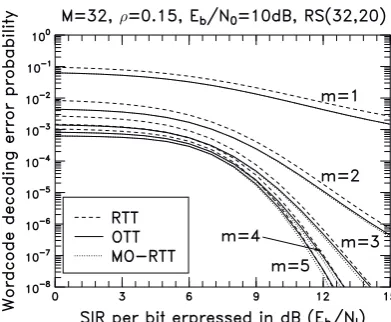
Finally, in Fig.6 we evaluated the codeword decoding error prob-ability of a RS(32,20) coded MFSK based SFH/SS system employing the OTT, RTT and MO-RTT erasure insertion schemes over
Nakagami-mfading channels having different fading parameters. In these inves-tigations, we assumed that the optimum thresholds were employed, whenever EAE decoding was used. From the results we observe that both the proposed OTT and MO-RTT erasure schemes outperform the RTT erasure insertion scheme, and as predicted, the MO-RTT era-sure scheme outperforms both the RTT and OTT eraera-sure insertion schemes, provided that all the erasure insertion schemes are operated at the optimum decision thresholds. However, when the channel qual-ity is poor (m= 1,2) or the SIR per bit is low (Eb/NI <9dB), the
codeword decoding error probability of the OTT and MO-RTT be-comes similar.
5. REFERENCES
[1] M. B. Pursley and W. E. Stark, “Performance of Reed-Solomon coded frequency-hop spread-spectrum communica-tions in partial-band interference,” IEEE Transaccommunica-tions on Communications, vol. 33, pp. 767–774, August 1985.
[2] Y. T. Su and L. der Jeng, “Antijam capability analysis of RS-coded slow frequency-hopped system,” IEEE Transactions on Communications, vol. 48, pp. 270–281, February 2000.
[3] A. J. Viterbi, “A robust ratio-threshold technique to mitigate tone and partial band jamming in coded MFSK systems,” in Proceedings of IEEE Military Communications Conferences Rec., pp. 22.4.1–22.4.5, IEEE, October 1982.
[image:4.595.313.489.113.265.2]partial-Figure 4: Average BER versus PBGI duty factor,ρ, performance for the uncoded MSFK based SFH/SS system over Nakagami-mfading channels with PBGI.
band interference,” IEEE Transactions on Communications, vol. 40, pp. 1231–1238, July 1992.
[5] M. K. Simon and M.-S. Alouini, “A unified approach to the per-formance analysis of digital communication over generalized fad-ing channels,” Proceedfad-ings of the IEEE, vol. 86, pp. 1860–1877, September 1998.
[6] R. E. Ziemer and R. L. Peterson, Digital Communications and Spread Spectrum Systems. New York: Macmillan Publishing Company, 1985.
0 3
6 9
12
15 0 0.2 0.4
0.6 0.8
1 -11
-10 -9 -8 -7 -6
L
o
g
o
f
co
d
ew
o
rd
d
ec
o
d
in
g
er
ro
r
p
ro
b
ab
il
it
y
Ratiothresh
old ( T)
Am plitu
de thresh old(Y
T)
[image:5.595.53.253.110.270.2]m=2, =0.15, M=32, Eb/N0=15dB, Eb/NI=15dB, RS(32,20)
Figure 5: Codeword decoding error probability versus the amplitude threshold,YTand the ratio threshold,λTfor the RS(32,20) FEC code
[image:5.595.317.487.138.306.2]using EAE decoding based on the MO-RTT erasure insertion scheme over Nakagami-mfading channels with PBGI.
[image:5.595.317.513.471.632.2]