1
Lattice Boltzmann parallel simulation of microflow dynamics over
structured surfaces
Wenning Zhoua,*, Yuying Yanb, Xunliang Liua, Baiqian Liua
aSchool of Energy and Environmental Engineering, University of Science and Technology
Beijing, Beijing 100083, China
bEnergy & Sustainability Research Division, Faculty of Engineering, University of
Nottingham, University Park, Nottingham NG7 2RD, UK
2
Abstract
In the present work, a parallel lattice Boltzmann multiphase model was developed to
investigate the effects of surface structures on wettabilities and flow dynamics in a
microchannel. The theory of wetting transition was firstly discussed. Then three types
including triangular, rectangle and hierarchical shaped microstructures were constructed on
the surface to examine the effects on wettabilities and drag reduction. It was found that flow
behaviour is strongly affected by the surface morphology of the channel. The results indicated
that hierarchical structures on the surface could improve the hydrophobicity significantly. For
rectangular structures, they can improve the hydrophobicity with the increase of height and
distance ratio h/d of the structures, and the improvement will reach its optimal hydrophobicity
when the value h/d is over a certain value of 0.6. Moreover, to accelerate computational speed,
the Open Multi-Processing (OpenMP) was employed for the parallelization of the model. A
maximum speedup of 2.95 times was obtained for 4 threads on a multi-core CPU platform.
Key words: Surface structures; Wettability; Drag reduction; Lattice Boltzmann method;
Parallel computing; OpenMP
NOMENCLATURE
c lattice speed
ci discrete particle speeds cs speed of sound
fi density distribution function
feq equilibrium distribution function
i
F forcing term
g gravitational acceleration
i
3 k effective thermal conductivity
wi weighting factor
G fluid-fluid interaction strength
Gt fluid-solid interaction strength
Greek Symbols
relaxation time
density
dynamic viscosity
kinetic viscosity collision operator
contact angle
1. Introduction
Superhydrophobic surfaces with apparent water contact angles higher than 150° and low
hysteresis have received immense interest in both scientific research and industrial field over
the past decade, such as self-cleaning, anti-corrosion, drag reduction, drug delivery, optical
devices, microfluidic devices and so forth [1]. These surfaces with high contact angle and low
contact angle hysteresis with a self-cleaning effect also exhibit low adhesion and drag reduction
for fluid flow [2]. Although superhydrophobic surfaces are usually designed with low surface
free energy materials, the method of chemical surface modification alone can typically lead to
water contact angles of up to 120°. To achieve extreme values of contact angles larger than
150° (near 180°), the modification on surface structure has to be utilized [3]. The effects of
surface roughness on wettability have been studied for a few decades after pioneering work
carried out by Wenzel [4] and Cassie-Baxter [5] who proposed theoretical models to predict
the wetting behaviour of the droplet in the non-composite and composite states. The
superhydrophobicity mechanism of the lotus leaf was theoretically analysed by Marmur [6]. It
4
in superhydrophobicity. A review paper regarding the impacts of surface roughness on
wettabilities can be found in Ref. [7]. In order to construct artificial superhydrophobic surfaces,
various methods and techniques have recently been developed. With these techniques, a great
number of different surface morphologies have been fabricated successfully, such as the pillar
morphology [8], flowerlike structure [9], ratchet-like morphology [10], the trapezoid
morphology [11], and so on. Meanwhile, numerical studies have also been carried out
extensively. Gao et al. [12] proposed a model to combine both factors caused by surface
structure and energy change. They claimed that the Cassie-Baxter equation should be adopted
for hierarchical roughness surface. Ambrosia et al. [13] used molecular dynamics simulations
to investigate the hydrophobic properties of water droplets on regular pillared surface. It should
be noted their work was limited to very small length and time scale due to the expensive
computational cost of molecular dynamics method. A lattice Boltzmann model was developed
to study the contact angles of droplets on the surfaces with regular roughness structures [14].
Lee et al. [15] has recently developed a lattice Boltzmann model to investigate the movement
of droplet on stripe-patterned surfaces. Jung et al. [16] also employed the lattice Boltzmann
method to determine the optimal geometry of microstructures to achieve superhydrophobicity.
Their simulation results were also compared with the results of measured wettability of
fabricated micro-hierarchical metal surface. However, the previous studies mainly focused on
the effect of surface structures on wettability and there are still few studies focusing on effects
of the surface topography on drag reduction.
Over the past few years, the lattice Boltzmann method (LBM), a mesoscopic approach, has
experienced tremendous advances and has been well accepted as a useful method to simulate
various complex fluid phenomena, such as multiphase /multicomponent flows [17-19],
electro-osmotic flow [20], micro/nano fluidics [21, 22], Magneto-hydrodynamic flows [23, 24], flows
5
nature and local dynamics, lattice Boltzmann method has several advantages over traditional
numerical methods, including the physical representation of microscopic interactions, the
easiness in dealing with complex geometries and parallelization of the algorithm. Recently,
parallelization has become an important feature for numerical methods as high performance
computing (HPC) are currently being designed for solving large-scale and complex engineering
problems. The widely used parallel algorithms for LBM include multi-core CPUs [29], General
Purpose GPU (GPGPU) [30] and hybrid CPU-GPU [31].
Based on our previous work on fabricating superhydrophobic surfaces and lattice Boltzmann
simulating of complex fluids [22, 23, 32, 33], we extended our research to numerical
investigating of structured surfaces. The objective of this study is to develop a parallel LBM
model to investigate the effects of different surface topography on the wettabilities and drag
reduction. The rest of this paper is organized as follows: Section 2 introduces the methodology,
including the multiphase lattice Boltzmann method, the wetting transition theory and the
parallel algorithm. The performance of the parallelization and simulation results on
wettabilities and drag reduction are given in Section 3. Finally, the conclusions are drawn in
Section 4.
2. Methodology
2.1 The multiphase lattice Boltzmann method
The pseudo-potential lattice Boltzmann model for multicomponent multiphase fluid was
employed in the present study [34]. The particle distribution function (PDF) of each
component of the multiphase fluid satisfies the following equation:
coll i
i
i x c t t t f xt
f ( , ) ( , ) (1)
where fi (x,t)
is the density distribution function of component and coll
is the collision
6 )) , ( ) , ( ( 1 , t x f t x
fi i eq
coll
(2)
where is a relaxation time which is related to its kinematic viscosity as 2( 0.5 )
t c
v s .
The equilibrium distribution function fi ,eq(x,t)
can be calculated by the following equation:
] 2 · 2 ) · ( · 1
[ 4 2
2 2 , s eq eq s eq i s eq i i eq i c u u c u c c u c w
f (3)
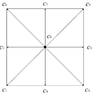
wherewi are weighting factors specific to the chosen lattice. For the two-dimensional
nine-velocity lattice Boltzmann model (D2Q9, as seen in Fig.1) employed in this work, wi are 4/9,
1/9 and 1/36, for i=0, 1-4, 5-8, respectively [35]. is the density of component . cs is the
sound speed. ci is the discrete velocities which are defined as:
) 8 , 7 , 6 , 5 , 4 / 2 / ) 5 ( ( ), sin , (cos 2 ) 4 , 3 , 2 , 1 , 2 / ) 1 ( ( ), sin , (cos 0 ), 0 , 0 ( i i c i i c i c i i i i i i i
(4)
where ci is the particle streaming speed and determined by cx/t. x, t are the lattice spacing and time step, respectively. The relation between cs and c can be expressed as
3 / c
cs . The macroscopic density and momentum of the th component are defined as:
i i f (5)
i i
i c
f u
(6)
The equilibrium velocity eq
u in Eq. (3) is defined as:
ueq u' F (7) where 'u is an effective velocity and F Fc, Fads, Fe,is the total force acting on the th
component including fluid-fluid interaction Fc, , fluid-solid interaction Fads, and external
7
/ ' uu (8)
In pseudo-potential model, the fluid-fluid interaction can be expressed as:
) )( ( ) , ( ) ( ) (
, x x G x x x x x
F
x
c
(9)
where G(x,x) is a parameter that controls the strength of the interaction force. (x) is the “effective density” of the th component defined as a function of the local particle density.
Different forms of (x) lead to different equations of state. G G for xx c; G G/4 for xx 2c and G 0 for otherwise. The most distinctive feature of the pseudo-potential
lattice Boltzmann method is that the phase segregation between different phases can emerge
automatically as a result of the particle interactions.
Martys and Chen [36] proposed to introduce the interaction force to describe the interaction
between a fluid and a wall. The interaction force is expressed as:
i ads
ads x G x s x x x
F ,( ) ( ) ( ')( ' ) (10)
otherwise c x x G c x x G G t t ads , 0 2 , 4 / , (11)
where the parameter Gt determines the fluid-solid interaction strength. s(x')=0 or 1 indicates fluid and solid node, respectively. The surface wetting characteristics can be controlled by
adjusting the fluid-solid interaction strength Gt. In this study, the fluid-solid interaction strength
8
Fig. 1. Typical two dimensional lattice Boltzmann model (D2Q9)
2.2 Wetting transition
In Young’s wetting state, when a liquid-gas interface meets a flat partial wetting surface, the
contact angle mearsured in the liquid, can be calculated from a balance of surface tension
forces at the contact line [37]:
LG SL SG
Y
( )/
cos (12)
where SG andSL are the solid-gas and solid-liquid surface tension, respectively.
For roughness surfaces, modified versions of Young’s equation are need to interpret the
pratical contact angles. Wenzel proposed a model where tha apparent contact angle depends
on a roughness parameter r and the contact angle on a flat surface [4]:
Y
W r
cos
cos (13)
where the roughness parameter r, also referred as roughness area ratio, is denoted as the ratio
of the actual surface-area over the projected area of the structures. As Wenzel assumed the
water would penetrate into the grooves on the rough surface when it spead on the surface, the
9
the grooves of roughness structures, it turns to Cassie-Baxter wetting state, in which the liquid
only contacts the solid through the top of the roughness, on a fraction f [39]:
1 ) 1 (cos
cosCB f Y (14)
where f is the fraction of the solid-liquid interface, (1-f) is the fraction on the gas-liquid
interface. The Cassie-Baxter state is related to the heterogeneous wetting regime.
According to the thermodynamically stability, the droplet prefers the state with a lower free
energy [38]. There is a threhold Young’s angle
C [40]. If Y>
C, the droplet can keep astable Cassie-Baxter state; On the other hand, if Y<
C, the droplet prefers to stay in Wenzelstate. In the present work, the wetting behaviours have been properly simulated by setting
fluid-solid interaction strength parameter and using proper boundary conditions, which will
be discussed in detail in the next section. Previous research also indicated that wetting
transition between Wenzel and Different Cassie-Baxter state can be predited by using lattice
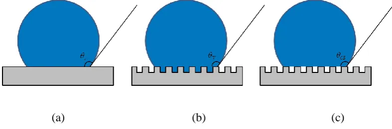
Boltzmann method [14]. Contact angles with different states are illustrated in Fig. 2.
[image:9.595.95.489.482.612.2](a) (b) (c)
Fig. 2. Contact angles of the droplet on the surfaces: (a) Young’s angle on the flat surface (b)
in Wenzel state (c) in Cassie-Baxter state
10
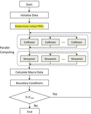
The most time demanding in the LBM model are the collision and streaming steps. Only one
CPU with single thread can be used in a serial code. As the collision step is purely local and
the streaming step only requires the data of the neighbouring nodes, the LBM model is very
suitable for parallel computing. To use multi-threads in the simulation, OpenMP (Open
Multi-Processing) was employed to achieve the parallelization of the proposed model. The parallel
implementation is demonstrated in Fig. 3. It should be noted that the variables in the parallel
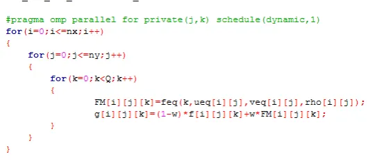
region should be carefully defined to avoid race condition. Part of the source code for
[image:10.595.149.452.317.696.2]parallelized collision step of the proposed LBM model is shown in Fig. 4.
Fig. 3. Flowchart of the parallel LBM model …
…
Calculate Macro Data
Boundary Conditions Determine Initial PDFs
Collision Collision Collision
Streamin g
Streamin g
Streamin g Start
Initialize Data
T<Tmax
End Parallel
Computing
Yes
11
Fig. 4. The source code for the parallelized collision step
3. Results and discussion
3.1 Performance of the proposed parallel computing model
To evaluate the effectiveness of the proposed parallel model, a series of simulation tests were
carried out on a DELL PC with Intel multi-core CPU i7-4790, 3.60GHz. 1-4 threads were
utilized in the simulations. Table 1 shows the results of computing times with different numbers
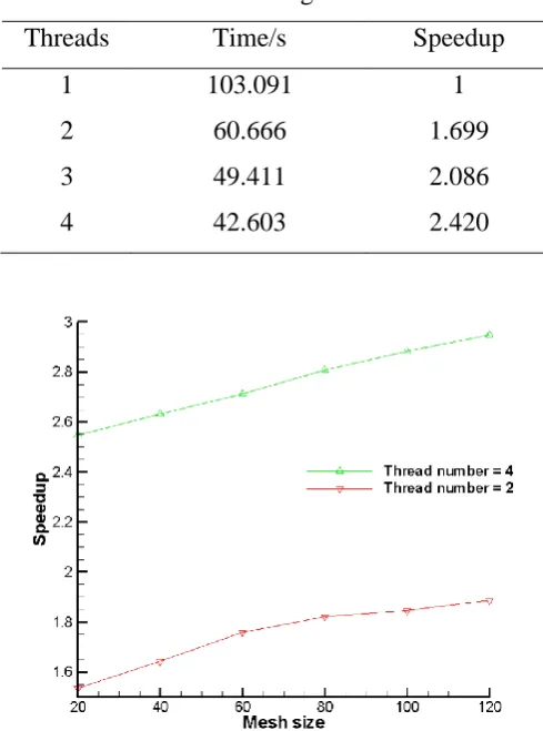
of thread used in the simulation. It is found that a maximum speedup of 2.42 times was achieved
by using 4 threads. Fig. 5 displays that the speedup increased with an increasing mesh size.
The X-axis represents the mesh size of the height of the channel (in lattice unit). The length of
the channel is fixed at 1500. It can be seen from this figure that the acceleration further
increased as the computational domain increased. A speedup of 2.95 times was obtained when
using 4 CPUs at the 1500×120 computational domain. It is indicated that the efficiency for a
larger or three dimensional computational domain of a more complex physical phenomenon
could be significantly improved when more CPU cores on high performance computing
12
Table 1 Computing times for 2000 time intervals on a DELL PC with multi-core CPU,
1500×50 grids
Threads Time/s Speedup
1 103.091 1
2 60.666 1.699
3 49.411 2.086
4 42.603 2.420
Fig. 5. The acceleration as a function of mesh size (lattice unit, height of the channel)
3.2 Evaluation of the proposed lattice Boltzmann model
In order to validate the proposed multiphase LBM model, we first simulated a droplet in an
unbounded domain. In the simulation, a series of droplets with different radii were initially
placed in the middle of a computational domain which was discretized into 100×100. Periodic
boundary conditions were employed on four sides of the computational domain. After the
equilibrium state was achieved, the pressure difference and radii of the droplets can be obtained.
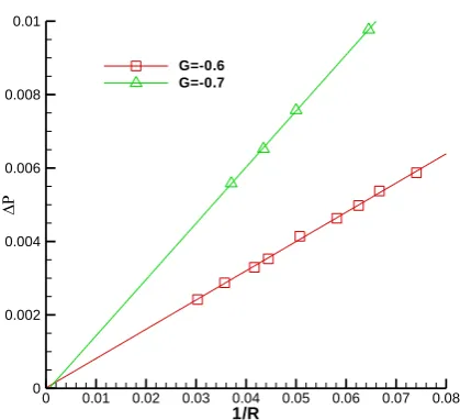
Fig. 6 demonstrates that the results of numerical simulation agree quite well with Laplace’s
law which could be written as:
R p
13
The values of pressure and radius are very sensitive to the final results because they are
relatively small. Therefore, carefulness is needed when choosing these values in simulating
cases. The values of the pressure should be a constant theoretically. However, since the
thickness of the interface is finite and both phases exist near the interface, the values of pressure
vary near the interface. Therefore, the values of pressure are taken away from the interface
where the pressure is almost a constant. As can be seen from Fig. 6, the slopes of the lines are
different with different fluid-fluid interaction strength. In other words, different surface
tensions could be achieved by varying the parameter of interaction strength parameter in the
[image:13.595.193.403.345.536.2]proposed model.
Fig. 6. The pressure difference as a function of its curvature with different fluid-fluid
interaction strength
3.3 Evaluation on surface wettabilities
In this section, the wettabilities of a single droplet on different surfaces were investigated. The
droplet was initially placed on the surfaces. After equilibrium status was achieved, different
contact angles were presented on different surfaces. Fig. 7 demonstrates different contact
angles between flat and rough surfaces with rectangular morphology which have the same
1/R
0 0.01 0.02 0.03 0.04 0.05 0.06 0.07 0.08 0
0.002 0.004 0.006 0.008 0.01
14
surface energy. Fig. 7a has a contact angle of 119.8° on flat surface, while 129.6° in rough
surface with rectangle morphology, as shown in Fig. 7b. It is observed that surface morphology
could have a positive effect on improving contact angles of the surface.
[image:14.595.153.444.177.301.2](a) (b)
Fig. 7. Contact angles on flat surface (a) and rough surface with rectangle morphology (b)
Fig. 8 presents the result of the contact angles as a function of the fluid-solid interaction
strength Gt. It can be seen that when |Gt|<0.3, the contact angle is larger than 90°, which is
consistent with the analytical result in [41]. It means that the hydrophobic surfaces could be
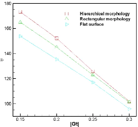
obtained by applying |Gt|<0.3. Fig. 9 displays the comparison of the three kinds of surfaces,
i.e., flat surface, rough surfaces with rectangular and hierarchical morphology, respectively.
The results show that for certain hydrophobic surfaces with the fluid-solid interaction strength
0.15<|Gt|<0.3, surface roughness have an evident effect on increasing contact angles, thus
enhancing the surface hydrophobicity. Overall the surface with hierarchical morphology has
the most profound effects. For instance, the contact angle on flat surface is 148.0° (|Gt|=0.15),
while it was increased to 173.3° on the surface with hierarchical morphology. It is also observed
that the effects of hierarchical morphology on increasing contact angles weaken for those
surfaces are less hydrophobic, i.e., the fluid-solid interaction strength |Gt|>0.25. It should be
noted that the sizes of the morphology may have different effects on changing the wettabilities
15
Fig. 8. The contact angle as a function of |Gt|, G=-0.6
Fig. 9. Contact angels on different surfaces with different morphology
3.4 Simulation for fluid dynamics in microchannels
3.4.1 Fluid flow in smooth channel
In the present study, a uniform of 1500×50 in lattice unit was applied representing
1500um×50um microchannel. To focus on flow dynamics in the channel and avoid the entrance
[image:15.595.179.400.341.544.2]16
part of channel was filled with fluid with a fixed velocity u, and we focused the flow dynamics
at the rest of the channel. The fluid was set with a fixed velocity u. For boundary conditions in
the proposed LBM model, periodic boundary conditions were employed at the inlet and outlet,
while half-way bounce back boundary conditions were utilised at the top and bottom of the
wall [42]. Fluidfluid interaction strength parameter in this study was set at a fixed value of
-0.6 throughout the simulation cases, i.e., fixed surface tension. As for fluid-solid interaction
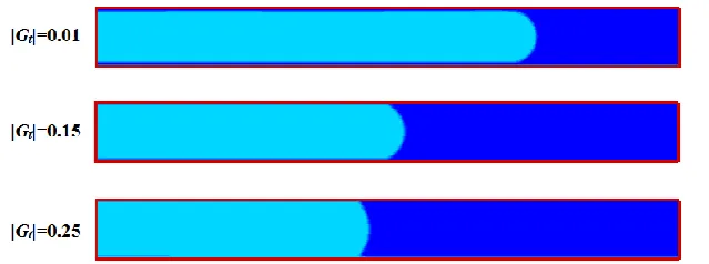
strength parameter |Gt|, a range of 0.01-0.3 was investigated. Fig. 10 displays the flows in the
channel at t=2000 in lattice time with different fluid-solid interactions. It is observed that a gas
layer is formed along the channel for |Gt|=0.01 which helps reduce the resistance from the
channel. Therefore, it shows smallest resistance and longest flow length in a certain time period.
As the fluid-solid interaction strength parameter |Gt| increases, the microchannel becomes less
hydrophobic. It should be noted that we assume the microchannel is more hydrophobic when
[image:16.595.124.444.458.577.2]it has a longer flow length in our simulation cases.
Fig. 10. Flow length in the microchannel with different interaction strength, t=2000
3.4.2 Fluid flow in the channel with surface structures
As discussed before, surface structures play an important role on influencing fluid flow
dynamics. The effects of the types and sizes of surface structures were investigated in this
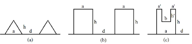
17
microchannel, as shown in Fig. 11. For all simulation cases, the sizes of the surface structures
are set at a=4, d=6 (in lattice unit, similarly hereinafter). The height for triangular structures is
h=2, while they are set at h=5 for rectangle and hierarchical ones. For hierarchical structures,
the sizes for the second layer structure are a’=1, b=2, h’=3. The effect of rectangle surface
structures on flow length at t=3000 is displayed in Fig. 12. It is found that the roughness helps
reduce the resistance of the channel, hence increase the flow length. The simulation results also
indicate that the increase of flow length with |Gt|=0.1 is much less than that of |Gt|=0.2. It means
that roughness does not have an obvious impact on the channels those already possess
superhydrophobic characteristics. Surface structures can improve its hydrophobicity, while
they do not have an obvious impact on superhydrophobic channels, which is consistent with
previous experimental work [43]. It can be seen from the figure that rectangle surface structures
have the effects of helping improve the surface hydrophobicity, especially for the hydrophobic
[image:17.595.142.457.453.525.2]surface with fluid-solid interaction strength 0.15<|Gt|<0.25.
18
Fig. 12. The effect of rectangle surface structures on the flow length
To further investigate the effects of surface structures’ size on hydrophobicity, the ratio of the
rectangle roughness height and distance h/d is introduced. Fig. 13 illustrates the effect of
rectangle structures with different h/d on the hydrophobic channel (|Gt|=0.15). It is observed
that the surface structures contribute to the hydrophobicity for most h/d values. However, when
the ratio is smaller than 0.3, the surface structures play a role of resistance, as shown region A
in the figure. As the increase of the ratio h/d, the flow length increases rapidly. However when
the ratio h/d>0.6, the flow length almost remains a constant as shown region C in the figure.
For the ratios falls in region B, the rectangle structures on the surface help improve the surface
hydrophobicity of the channel. The hydrophobicity reaches its maximum when h/d is around
0.6 for rectangle surface structures. An increasing ratio of h/d thereafter will not help improve
the hydrophobicity further. The results could be helpful for designing superhydrophobic
19
Fig. 13. Flow length in the channel with rectangle surface structures as a function of the ratio
h/d, |Gt|=0.15
To achieve further superhydrophobicity, hierarchical roughness is usually designed on the
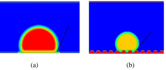
surface of channel, as shown in Fig 11. Fig. 14 displays the flow lengths in different
microchannels with different morphologies. As can be seen from the figure, the flow length in
the channel with hierarchical morphology is longer than that with rectangular morphology. It
indicates that the microchannel with hierarchical morphology is more hydrophobic than that
with rectangular morphology (h/d=5/6). Comparisons of the effects of rough channel with
triangle, rectangle and hierarchical surface structures on hydrophobicity are shown in Fig. 15.
It is found that the hierarchical surface structures have the most significant effect on the
hydrophobicity when the fluid-solid interaction strength parameter falls into 0.1<|Gt|<0.2.
Hierarchical surface structures have a more evident improvement on hydrophobicity compared
with other rectangular surface structures in this region. Compared with the smooth channel, the
triangular surface morphology does not have an obvious effect on changing hydrophobicity.
For those channels already with high hydrophobicity (|Gt|=0.1), triangular surface structures
h/d
L
0.2 0.4 0.6 0.8 1
320 330 340 350 360
A
B
20
may have an effect of reducing the hydrophobicity. It should be noted that when fluid-solid
interaction strength |Gt|>0.2, the effects of hierarchical structures on improving hydrophobicity
decrease dramatically, and eventually they will play a role of resistance of the channel. With
these rules in mind, superhydrophobic channels could be created by patterning proper
[image:20.595.137.465.234.351.2]hierarchical structures on hydrophobic channels.
Fig. 14. Flow length in microchannels with (a) rectangular morphology, (b) hierarchical
morphology, |Gt|=0.15, t=4000
[image:20.595.168.409.444.667.2]21
To investigate drag reduction effect, the frictional resistance coefficient is introduced by
) | (|
2 2
l u pd
cf . The local frictional resistance coefficient at t=2000 and x=L/2 in four
kinds of channels is displayed in Fig. 16. The horizon abscissa 1 stands for the channel with
the hierarchical surface structures; 2, 3 represent h/d=5/6, h/d=4/6 rectangular surface
structures, respectively; 4 denotes the channel with triangular surface structures. It can be seen
from the figure that the channel with the hierarchical surface structures has the smallest
frictional resistance coefficient. It indicates that the pressure drop in the channel with
[image:21.595.175.421.326.549.2]hierarchical roughness is the smallest compared with other rough channels.
Fig. 16. The frictional resistance coefficient in different microchannels with different
morphology
4. Conclusions
In the present work, a parallel lattice Boltzmann method was developed to investigate the
effects of surface structures on the wettabilities and drag reduction of the microchannel. The
theory of wetting transition and mechanism of drag reduction were analysed. We have channels with different morphology
C
f
1 2 3 4
22
discussed how the Wenzel and Cassie-Baxter equations determine the homogeneous and
heterogeneous wetting. Multi-core CPU programming was introduced for the parallelization of
the LBM model. A maximum speedup of 2.95 times was achieved for 4 threads on a
multi-core CPU i7-4790 platform. In addition, triangular, rectangular and hierarchical surface
microstructures were then constructed on the surface of the microchannel. For rectangular
structures, it is found that the ratio of height and the distance h/d has a great effect on
hydrophobicity of the surfaces. As the ratio increases, the surface morphology could help
increase the hydrophobicity. However, when the ratio increases further, i.e., h/d >0.6, the
surface morphology does not have an evident effect on improving hydrophobicity. For
hierarchical surface structures, the simulation results show that they have the most pronounced
effects on improving hydrophobicity and drag reduction of the channel compared with
triangular and rectangular surface structures. The results could provide helpful information for
the design and optimization of superhydrophobic surfaces by patterning surface
microstructures.
Acknowledgements
This work is supported by the Fundamental Research Funds for the Central Universities (Grant
no. FRF-TP-15-081A1) and National Science Foundation of China (Grant no. 51676013).
References
[1] Marmur A. The lotus effect: superhydrophobicity and metastability. Langmuir. 2004;20:3517-9. [2] Bhushan B, Jung YC. Natural and biomimetic artificial surfaces for superhydrophobicity, self-cleaning, low adhesion, and drag reduction. Progress in Materials Science. 2011;56:1-108.
[3] Blossey R. Self-cleaning surfaces - virtual realities. Nature Materials. 2003;2:301-6.
[4] Wenzel RN. RESISTANCE OF SOLID SURFACES TO WETTING BY WATER. Industrial & Engineering Chemistry. 1936;28:988-94.
23
[8] Zhang H, Li W, Liu H, Cui D. Thermodynamic analysis on superhydrophobicity based on the design of a pillar model. Soft Matter. 2012;8:10360-9.
[9] Guo F, Su X, Hou G, Li P. Bioinspired fabrication of stable and robust superhydrophobic steel surface with hierarchical flowerlike structure. Colloids and Surfaces A: Physicochemical and Engineering Aspects. 2012;401:61-7.
[10] Sheng X, Zhang J. Directional motion of water drop on ratchet-like superhydrophobic surfaces. Applied Surface Science. 2011;257:6811-6.
[11] Moradi S, Englezos P, Hatzikiriakos SG. Contact Angle Hysteresis of Non-Flattened-Top Micro/Nanostructures. Langmuir. 2014;30:3274-84.
[12] Gao N, Yan Y. Modeling Superhydrophobic Contact Angles and Wetting Transition. Journal of Bionic Engineering. 2009;6:335-40.
[13] Ambrosia MS, Ha MY, Balachandar S. The effect of pillar surface fraction and pillar height on contact angles using molecular dynamics. Applied Surface Science. 2013;282:211-6.
[14] Yagub A, Farhat H, Kondaraju S, Singh T. A lattice Boltzmann model for substrates with regularly structured surface roughness. J Comput Phys. 2015;301:402-14.
[15] Lee C, Lyu S, Park JW, Hwang W. Lattice Boltzmann simulation of the movement of droplets on stripe-patterned surfaces having different wettability. Adv Eng Softw. 2016;91:44-50.
[16] Jung M, Kim T, Kim H, Shin R, Lee J, Lee J, et al. Design and fabrication of a large-area superhydrophobic metal surface with anti-icing properties engineered using a top-down approach. Applied Surface Science. 2015;351:920-6.
[17] Yan YY, Zu YQ. A lattice Boltzmann method for incompressible two-phase flows on partial wetting surface with large density ratio. J Comput Phys. 2007;227:763-75.
[18] Stensholt S, Øien A. Lattice Boltzmann simulations of the motion induced by variable surface tension. Adv Eng Softw. 2011;42:944-53.
[19] Zhang M, Xu K, He Y, Jivkov AP. Pore-scale modelling of 3D moisture distribution and critical saturation in cementitious materials. Construction and Building Materials. 2014;64:222-30.
[20] Wang M, Wang JK, Li ZX. Lattice Poisson-Boltzmann simulations of electro-osmotic flows in microchannels (vol 296, pg 729, 2006). J Colloid Interf Sci. 2006;300:446-.
[21] Suga K, Takenaka S, Ito T, Kaneda M, Kinjo T, Hyodo S. Evaluation of a lattice Boltzmann method in a complex nanoflow. Phys Rev E. 2010;82:-.
[22] Zhou WN, Yan YY, Xu JL. A lattice Boltzmann simulation of enhanced heat transfer of nanofluids. Int Commun Heat Mass. 2014;55:113-20.
[23] Zhou WN, Yan YY. Numerical Investigation of the Effects of a Magnetic Field on Nanofluid Flow and Heat Transfer by the Lattice Boltzmann Method. Numerical Heat Transfer, Part A: Applications. 2015;68:1-16.
[24] Dellar PJ. Lattice Boltzmann magnetohydrodynamics with current-dependent resistivity. J Comput Phys. 2013;237:115-31.
[25] Zhang M, Ye G, Breugel Kv. Microstructure-based modeling of permeability of cementitious materials using multiple-relaxation-time lattice Boltzmann method. Comp Mater Sci. 2013;68:142-51. [26] Grucelski A, Pozorski J. Lattice Boltzmann simulations of heat transfer in flow past a cylinder and in simple porous media. Int J Heat Mass Tran. 2015;86:139-48.
[27] Zhang J, Yan G. Lattice Boltzmann model for the bimolecular autocatalytic reaction–diffusion equation. Appl Math Model. 2014;38:5796-810.
[28] Zhang M, Ye G, van Breugel K. Modeling of ionic diffusivity in non-saturated cement-based materials using lattice Boltzmann method. Cement and Concrete Research. 2012;42:1524-33.
[29] Puurtinen TA, Toivanen JI, Mattila K, Hyväluoma J, Nash RW, Coveney PV, et al. Coupling of lattice-Boltzmann solvers with suspended particles using the MPI intercommunication framework. Adv Eng Softw.
24
[31] Ye Y, Li K, Wang Y, Deng T. Parallel computation of Entropic Lattice Boltzmann method on hybrid CPU–GPU accelerated system. Comput Fluids. 2015;110:114-21.
[32] Gao N, Yan YY, Chen XY, Mee DJ. Superhydrophobic surfaces with hierarchical structure. Materials Letters. 2011;65:2902-5.
[33] Gao N, Yan Y, Chen X, Mee DJ. Nanoparticle Induced Morphology and Hydrophilicity of Structured Surfaces. Langmuir. 2012.
[34] Shan XW, Chen HD. Lattice Boltzmann Model for Simulating Flows with Multiple Phases and Components. Phys Rev E. 1993;47:1815-9.
[35] Aidun CK, Clausen JR. Lattice-Boltzmann Method for Complex Flows. Annu Rev Fluid Mech. 2010;42:439-72.
[36] Martys N, Chen H. Simulation of multicomponent fluids in complex three-dimensional geometries by the lattice Boltzmann method. Phys Rev E. 1996;53:743-50.
[37] Young T. An essay on the cohesion of fluids. Philosophical Transactions of the Royal Society of London. 1805:65-87.
[38] Marmur A. Wetting on hydrophobic rough surfaces: to be heterogeneous or not to be? Langmuir. 2003;19:8343-8.
[39] Cassie A, Baxter S. Wettability of porous surfaces. Transactions of the Faraday Society. 1944;40:546-51.
[40] Zheng Q-S, Yu Y, Zhao Z-H. Effects of hydraulic pressure on the stability and transition of wetting modes of superhydrophobic surfaces. Langmuir. 2005;21:12207-12.
[41] Sukop MC, Thorne DT. Lattice Boltzmann modeling: An introduction for geoscientists and engineers: Springer Verlag; 2006.