Abstract— The influence of custom microphone housings on the acoustic directionality and frequency response of a multi-band bio-inspired MEMS microphone is presented. The 3.2mm by 1.7mm piezoelectric MEMS microphone, fabricated by a cost-effective multi-user process, has four frequency bands of operation below 10 kHz, with a desired first order directionality for all four bands. 7x7x2.5 mm3 3D-printed bespoke housings with varying acoustic access to the backside of the microphone membrane are investigated through simulation and experiment with respect to their influence on the directionality and frequency response to sound stimulus. Results show a clear link between directionality and acoustic access to the back cavity of the microphone. Further, there was a change in direction of the first order directionality with reduced height in this back cavity acoustic access. The required configuration for creating an identical directionality for all four frequency bands is investigated along with the influence of reducing the symmetry of the acoustic back cavity access. This work highlights the overall requirement of considering housing geometries and their influence on acoustic behavior for bio-inspired directional microphones.
Index Terms—3D-printing, acoustic response, bio-inspired directional microphones, MEMS, microphone housings
I. INTRODUCTION
HE use of directional sound receivers for sound source localization or improvement of hearing aid technologies through suppression of unwanted sound sources is a research topic with strong biomedical, entertainment and defense industry interest, with solutions depending on signal processing approaches or specialized mechanical microphone designs. Current commercially available products rely on multiple miniaturized microphones with a minimal spacing to solve the localization problem. Research in single element directional receivers has been accelerated by bio-inspired designs, specifically after Miles et al.’s initial investigations in the hearing properties of the parasitoid fly Ormia ochracea [1],
Manuscript received February xx 2017. This work was supported by the EPSRC under grant EP/M026701/1 and by the European Research Council under the European Union’s Seventh Framework Programme (FP/2007-2013) / ERC Grant Agreement n. [615030]. Data supporting this research is openly available from http://dx.doi.org/10.15129/fc076d32-f961-407e-90c1-d1f06b1c99fa.
R. Bauer, Y. Zhang, J. C. Jackson, D. Uttamchandani and J. F. C. Windmill are with the Department of Electronic and Electrical Engineering, University of
which has a remarkable sound source localization potential despite its hearing organ inter-aural distance only measuring 520 µm. Since Miles’ original investigation and subsequent bio-inspired design proof using Microelectromechanical Systems (MEMS) technology [2], a range of investigations showcasing Ormia inspired MEMS microphones with transduction mechanisms ranging from capacitive readout [3]– [6], optical readout [7]–[11] to piezoelectric readout [12]–[16] have been reported. These investigations have shown directionality resolutions with directivity index of 5 dB, with minimum resolvable sound cues as low as 15 dBA at 2 kHz. The latest design proposals include a full pre-amplifier/signal processing unit and demonstrator [5].
While some of these investigations have progressed to a system development stage, most proposed designs still have only a single frequency directionality, with the off resonance behavior showing a low response. Only few investigations aiming to broaden the frequency band have been shown to date, with one based on cantilevers [17] and a second showcasing the balanced response between two Ormia movement modes in an asymmetric design [18]. In our previous work [15] we have shown the expansion from 2 movement modes to multi-band operation with the inclusion of multiple membranes set inside each other, with all operation frequency bands below 15 kHz.
For both the single and multi-band frequency responses one missing investigation is determined by the packaging constraint of the individual MEMS chips. While the directionality of a single frequency band design has no constraint due to the potential to house the microphone in any desired orientation, this does not hold true for multi-band operation. In this case, taking care of the alignment of the directionalities of all working frequency bands is essential. In previous works it has been proposed mathematically that access to the backside of the movement membrane of the MEMS microphone plays an important role for this [19], however no full experimental or simulative investigation on the influence of the acoustic
Strathclyde, Glasgow, G1 1XW, U.K. (e-mail: ralf.bauer@strath.ac.uk, yansheng.zhang.101@strath.ac.uk, joseph.jackson@strath.ac.uk d.uttamchandani@strath.ac.uk, james.windmill@strath.ac.uk).
W. M. Whitmer, W. O. Brimijoin and M. A. Akeroyd are with the Scottish Section, MRC/CSO Institute of Hearing Research, Glasgow, G31 2ER, U.K. (e-mail:Bill.Whitmer@nottingham.ac.uk, Owen.Brimijoin@nottingham.ac.uk, Michael.akeroyd@nottingham.ac.uk).
Influence of microphone housing on the
directional response of piezoelectric MEMS
microphones inspired by
Ormia ochracea
Ralf Bauer, Yansheng Zhang, Joseph C. Jackson, William M. Whitmer, W. Owen Brimijoin, Michael
A. Akeroyd, Deepak Uttamchandani
, Senior Member IEEE
, and James F. C. Windmill,
Member IEEE
constraints imposed by the MEMS housing has yet been shown. In the work presented here a new multi-band MEMS microphone with frequency bands operating below 10 kHz is demonstrated and used as an example to investigate the influence of the microphone housing and backside air cavity on the microphone directional performance. Acoustic access to this air-cavity is evaluated both through FEM simulations and experimental investigations. The MEMS transduction mechanism in this work is a piezoelectric read-out using aluminum nitride (AlN) active layers, with devices fabricated in a cost-effective multi-user process (PiezoMUMPs). The housing influence is evaluated both in respect of the frequency response as well as the directionality behavior. In section II the device and housing design and fabrication is discussed, next to the specification of the experimental setup and simulation steps. Section III details the results of both experimental and simulative investigations, with section IV closing with a discussion of the results and their significance.
II. MATERIALS AND METHODS
A. MEMS design and fabrication
The design of the new bio-inspired MEMS microphone is based on a design first used by Kuntzman et al. [20] to increase bending stresses at piezoelectric active areas through the inclusion of bending beams next to the torsional springs required to mimic the two movement mode shapes of the hearing organ of the fly Ormia ochracea. To increase the frequency bands in which the microphone operates, two membranes set inside each other are used (see Fig. 1). Both membranes have a common torsion spring axis and connection to the substrate, which is 200 µm offset to the geometric center axis to enable the same acoustic directionality response throughout the four frequency bands of operation. An asymmetric system is required for this as in a design that directly mimics Ormia’s symmetric paradigm a different directional response between the two distinct movement modes of a membrane exist. The pressure gradient dependent rocking mode (out-of-phase movement of the membrane ends) follows a sine dependency while the pressure dependent bending mode (in-phase movement of the membrane ends) follows a cosine
dependency [15], [18]. By using an offset to the symmetry axis this can be shifted to a cosine dependency for both movement modes, which enables a constant directionality response throughout the frequency bands of operation. The overall microphone dimensions are 3.22 mm by 1.7 mm for the outer membrane and 1.98 mm by 0.9 mm for the inner membrane. The bending beams of both membranes have a width of 100 µm and are connected to the surrounding substrate next to the 20 µm by 250 µm torsion springs and to the back of the membrane at the other end. The outer bending beams additionally have a 140 µm long extension to the substrate to reduce the compliance and therefore all movement mode frequencies. The design incorporates six distinct sensing channels, 4 of which sense bending stresses of the outer membrane and 2 of which sense bending stresses of the inner membrane. Each channel contains a sensing area using a 500 nm thick piezoelectric film (AlN) converting elastic strain through acoustic excitation into a voltage potential that is read out through aluminum electrodes routed to the bulk substrate of the chip.
The microphones are fabricated using a multi-user silicon-on-insulator process, PiezoMUMPs [21], offered by Memscap Inc. The device layer of the process consists of 10 µm thick doped silicon, which is used for all moving parts, with a substrate thickness of 400 µm of the MEMS chips. The doped nature of the device layer allows it to be used as ground electrode for the piezoelectric read-out, with the 500 nm thick AlN piezoelectric sensing layer sitting between the device layer and a 1 µm thick layer of Al used as top electrode. The moving parts of the design are released through a full backside etch step through the 400 µm substrate, enabling acoustic access to the backside of the membrane. The device layer thickness of 10µm is significantly thicker than the layer thickness of most commercially available MEMS microphones which will limit the achievable signal levels through the AlN layer. However, the design principles employed for the reported microphones can be presented through the use of a cost-effective multi-user process.
B. 3D-printed housings
[image:2.612.316.565.545.697.2]The general schematic of the microphone housings used to
[image:2.612.49.295.549.717.2]Fig. 1. SEM image of the four band Ormia inspired MEMS microphone.
evaluate the influence on the acoustic response is shown in Fig. 2. The 5.5 mm by 5.5 mm MEMS chip is placed in a rectangular housing with 7 mm by 7 mm footprint and 2.5 mm height. The backside air cavity consists of a 500 µm height, 5mm by 5mm cross-section volume common to all holders. Added to this is a volume generated by the height of air inlets used to investigate their influence on the directional behavior. The backside air inlet height used ranges from 150 µm to 750 µm. Access to balance the acoustic pressure at the backside of the microphone membrane is therefore present through the air inlets (apart from one fully closed backside configuration) and 10 µm wide gaps between the moving membrane and the substrate of MEMS chip. This backside access through acoustic inlets of the housing works in a similar manner to slits in acoustic baffles of e.g. Ribbon microphones, where the slit adapts the acoustic impedance and allows the generation of figure of 8, unidirectional or omnidirectional responses [22]. The main difference from this well understood concept is the maintained access to the backside through the 10µm slits in the silicon and the application in this work to a combined pressure and pressure gradient microphone instead of the classical ribbon microphone concept.
Fabrication of the investigated housing configurations is handled through a stereolithography 3D-printer (EnvisionTec Desktop Aureus) with axial resolution of 25 µm and lateral resolution of 43 µm. The used liquid photopolymer resin is EnvisionTec’s proprietary resin R11.
The MEMS and housings are assembled using a thin layer double sided adhesive tape at the edge of the chip insets, sealing the sides of the MEMS chips into the housing. Electrical connectivity is achieved through wire bonding to 0.3 mm wide metal bond-pads glued into recessions in the 3D-print part in combination with 150 µm diameter thin wires for routing of the electrical signals to an instrumentation amplifier pre-amplifier stage.
C. FEM simulations
To theoretically analyze the influence of the back-side air cavities and acoustic backside access to the membrane of the Ormia inspired MEMS microphones, models for a full acoustic frequency domain simulation were built in COMSOL Multiphysics. The simulations include the full geometry of the MEMS chip plus 3D-printed holders, with height h of air inlets ranging from 10 µm to 750 µm next to a fully closed geometry.
The 500 nm thick AlN layer of the device has been omitted in this case to reduce computational requirements defined through the high aspect ratios present in the chip. For each MEMS and holder combination an initial Thermoviscous Eigenfrequency simulation is undertaken to estimate the damping induced by the backside air-cavities and the shear flow at the 10 µm gaps between the moving membrane and MEMS substrate. This initial model consists of a combination of solid-mechanics, acoustic and thermovisco-acoustic physics with the incident sound field modelled as a plane wave excitation incident normal to the membrane. The resulting complex eigenvalues of the simulated resonance modes of the MEMS microphone are used to calculate Rayleigh damping values for each mode and housing configuration. This is based on the assumption that the Rayleigh mass damping parameter αdm = 0. A second order
polynomial fit to the calculated values at the four resonance modes leads to an equation for the Rayleigh stiffness damping parameter β, which is used in the frequency domain acoustic response simulations as a material damping term. The frequency domain acoustic simulations are evaluated with a full frequency sweep between 1-10 kHz, followed by a directionality sweep at the frequencies of the main responses of the four frequency bands.
D. Laser vibrometry
To confirm the MEMS movement mode shapes and mechanical response of the chips, a scanning laser vibrometer was used (Polytec MSA-100-3D). The setup allows acoustic excitation with a ~45° incidence angle to the membrane normal, with a scanned response evaluation using a full 1-10 kHz frequency FFT response by using a swept excitation through a speaker.
E. Electrical measurements
The setup shown in Fig. 3 is used to evaluate the electrical response to acoustic stimulus of the MEMS and holder
Fig. 4. FEM simulation and LDV measurements of the Eigenmode-shapes relevant to the four directional microphone frequency bands.
[image:3.612.49.296.50.159.2] [image:3.612.325.564.512.711.2]combinations. The microphone system is mounted on a post centered on a custom built rotation stage with 0.9° step angle. The stage is set within an anechoic box, with a 2” speaker (Visaton FRS-5) placed at 1 m distance as acoustic source. A reference microphone (B&K 4138) is placed in the identical position to the microphone system under test for evaluation of the absolute acoustic pressure of the speaker over the used frequency range of 1-10 kHz. The electrical response of the microphone-holder combination is measured using the wires integrated in the 3D-printed holder, with the signals routed to a pre-amplifier stage outside the anechoic box consisting of a home-build circuit using a Texas Instruments INA128 instrumentation amplifier and a 4th order filter with a bandpass
between 100Hz-18kHz realized through LM833 amplifier stages. The instrumentation amplifier had multiple gain settings, with the used setting having a gain of 10. The pre-amplifier signals are further amplified through a commercial SR850 lock-in amplifier (LIA) and recorded with a digital oscilloscope (Tektronix TBS1032B). The read-out of both a frequency response sweep and a directionality evaluation was automated through LabVIEW, with the rotation stage controlled by an Arduino Due. The speaker was driven with an Keysight 33210A signal generator, using a single frequency sinusoidal excitation.
III. RESULTS
The evaluation of the acoustic response influence of the presented housings for directional MEMS microphones based on the hearing mechanisms of Ormia ochracea is split into a frequency response evaluation and the evaluation of the directionality response change. For the frequency response a direct comparison between a closed and open backside holder
is shown, while for the directionality response experimental and simulated results comparing closed backside holders and holders with 4 backside inlets, comparing holders with inlets along the long or short side of the microphone membrane, and comparing varying heights of the backside inlets are shown. The presented simulations also cover a full variation of the inlet height h.
A. Frequency response
The Eigenfrequencies of the new MEMS design without including the influence of a holder is simulated and measured using the silicon chip as the structural surrounding in the simulations and the vibrometer for the experimental characterization. The resulting mode shapes and frequencies are shown in Fig. 4. The movement shapes are well matched between simulations and experiments for all four main resonance frequencies. The simulated frequencies underestimate the experimentally observed Eigenfrequencies due to the omission of the piezoelectric AlN layer within the simulation, which induces an additional compliance to the movement modes. The simulated resonance frequencies are 2 kHz, 3.6 kHz, 4.95 kHz and 8.6 kHz for the outer rocking mode, outer bending mode, inner rocking mode and inner bending mode, respectively. This compares with experimentally measured resonance frequencies of 2.1 kHz, 3.85 kHz, 5.2 kHz, and 8.95kHz. Due to the coupling of the two inset membranes, each movement mode includes a response in both membranes, with in-phase or out-of-phase contributions of vertical displacements.
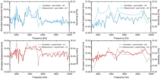
[image:4.612.49.565.48.301.2]The full frequency response between 1-10 kHz of the devices being housed in a holder without backside air inlets and with 4 backside air inlets with h = 750 µm is shown both theoretically and experimentally in Fig. 5. The excitation direction in all
frequency response cases is from the top, normal to the membrane. The FEM simulations use Rayleigh damping factors calculated through the aforementioned Thermoviscous Eigenfrequency simulations and have a frequency spacing of 50Hz, similar to the measured frequency response. The simulations are evaluated using the vertical displacement of the tips of each membrane, with Ch1 in Fig. 5 being the tip of the outer membrane’s long side and Ch5 the tip of the outer membrane’s short side. The four frequency responses shown in Fig. 5 correspond to the 4 inlets holder (top) at Ch1 and Ch5, and the closed backside holder (bottom) at Ch1 and Ch5. The experimental measurement of the devices shows the electrical signals recovered from the piezoelectric actuators through the mentioned setup shown in Fig. 3. In all four cases the simulated first frequency mode (rocking, in-phase) is clearly visible in the simulated movement response, but has an almost negligible electric response. This is explained by the relative low stress present at the piezoelectric actuators for this movement mode. For the open holder configuration an increase in the highest resonance response conversely results from a high stress load at the actuator positions. Comparing the two holder configurations with and without backside acoustic access shows in the simulations an increase of the response between the resonances for the closed configuration, which is amplified in the experimental response. The broadening between the 2nd and 3rd
resonance is clearly visible for Ch1 and shows the predicted response dip in Ch5. The highest resonance is in this case only slightly underestimated by the simulations relative to the lower resonance responses. The measured electrical output is higher than the corresponding simulated mechanical response despite the broadening of the resonance peaks resulting from the increased damping through a closed backside air cavity. B. Directionality with varying backside air gap height
The more important aspect investigated for different
microphone holder configurations is their influence on the directional response of the bioinspired MEMS microphones. For this a comparison between the two cases detailed in the frequency response, one with fully closed backside and one with access via four inlets with 750µm height, is undertaken. Both the simulation and experimental results are presented in Fig. 6 with the resulting acoustic response directionality along the elevation. The simulations are conducted using a 1Pa plane wave excitation and the acoustic structure interaction in COMSOL, with the damping calculated through the thermoviscous evaluation as previously mentioned. The experimental results were recorded using an automated rotation stage and 3.6° angular resolution while playing a single tone excitation at each of the four resonance frequencies determined previously. The closed holder simulated response shows a 1st
order directionality with a maximum response in plane with the microphone membrane for the lowest frequency, while all further frequencies show an omni-directional behavior. The experimental results show a matching behavior, with the first frequency band measurement missing due to a low signal to noise ratio as visible in the frequency response. For the four inlet holder system a 1st order directional acoustic response is
simulated for all frequency bands, with the direction of the first frequency slightly offset from the microphone membrane normal direction and the rest showing a maximum at the normal. The experimental data again shows a good overlap, with slightly unbalanced front-back amplitude ratios over the four frequency bands. The on-axis to off-axis ratio for all four frequency bands is -15dB, -19dB, -18dB, and -18dB. The 15° offset at the first resonance frequency is believed to originate from the coupled membrane behavior of the asymmetric design, with front/back unbalance occurring due to the same reasons.
To determine the required height of the backside air inlets for achieving a similar 1st order directional acoustic response at all
[image:5.612.63.278.50.278.2]frequency bands, a simulated height sweep looking at air inlet heights from 10µm to 750µm was undertaken in the FEM software. The resulting directionality patterns at all four
Fig. 6. Simulated (dotted lines) and measured (solid lines) directional acoustic response at the four frequency bands of the MEMS microphone for the four inlet holder (blue) and holder without air inlets (red).
[image:5.612.317.565.50.254.2]frequency bands are shown in Fig. 7. In the first frequency band a gradual rotation of the directionality from an in-plane orientation to a normal orientation relative to the MEMS membrane is present when increasing the backside air inlet height. A height of 150µm has still an offset angle of 50° while the 750µm height has reduced the offset to 15°. In the other bands the omni-directional behavior of a closed back-cavity shows a hint of a directional pattern with small gaps (e.g. 10µm) while gaps above 150µm have a first order directional pattern with almost normal orientation. The maximum angular offset for these cases for the 750µm inlet height is <5°. This led to the use of an inlet height of 750µm to limit the overall system size of the MEMS and holder combination while still creating a homogeneous directionality through all frequency bands of interest. The shift in directionality that occurs results from changes to the acoustic impedance of the back-cavity through the inlets. Contrary to standard pressure gradient microphone where backside access allows changes to the acoustic impedance in order to change the directional response from bidirectional to unidirectional before leading to an omnidirectional response [22], in the case of the Ormia inspired microphones used here the change of the acoustic impedance through changes to the backside inlets of the housing rotates the bidirectional resonance rather than reducing the backside response as shown in the simulations in Fig. 7. This behavior leads to the clear recommendation to design housings with low acoustic impedance to reduce influence on directionality established through the membrane design.
C. Directionality with varying backside air gap position To investigate if an influence on the directionality of the acoustic response is present for variations of the position of the backside air cavity inlets relative to the microphone membrane orientation, 3D-printed holders with two inlets either along the
major or minor axis of the MEMS chip were created. Both investigated cases have identical holder configurations next to this, with the first holder having two 750µm high inlets on the sides of the spring connections of the microphone design (long axis), while the second configuration has been rotated in the plane of the membrane by 90° and has inlets at the sides of the membrane highest movement (short axis). For both cases FEM simulations and electrical measurements were performed with the same setup as in the previously shown configurations. The resulting directionality projections along the elevation are shown in Fig. 8. For both cases a good agreement between the simulations and measurements can be seen for each orientation of the maximum sound response. However, specifically at the highest resonance frequency, the shape of directionality pattern changes from the desired first order directionality to a pattern more resembling a subcardioid or shotgun directivity. Having the inlets at the end of the long axis of the membrane shows an almost identical behavior to the configuration with four air inlets and identical inlet height. The directionality at the first resonance frequency shows an angular offset of 23°, while the other three frequency bands have a first order directional response with a maximum at an incident normal to the membrane. Having the inlets at the sides of the membrane spring connections results in a larger offset angle of 54° for the first frequency band, which is confirmed both experimentally and in simulation. The three subsequent frequency bands show experimentally and in simulation a reduced directionality for the case with the backside inlets positioned at the membrane side, with an additional experimentally determined tilt of the maximum response by 11° for second band and 21° for third resonance band. Specifically, for the highest frequency band the measured directionality resembles more closely a response equivalent to the one obtained from a holder and microphone system with a closed backside cavity than the similar open cavity cases.
IV. DISCUSSION
[image:6.612.63.277.49.269.2]The presented multi-band bio-inspired MEMS microphones show a colored spectrum in their frequency response due to the four resonance bands employed for creating higher signal amplitudes in the 1-10 kHz range. To reduce the influence of the frequency spectrum colouring and the frequency dependency the resonant modes are designed to be close to each other while still covering the acoustic range of interested, with the aim of multiple resonances stacking close enough together to create a resonant acoustic sensor with the potential for improved noise filtering as employed e.g. by Baumgartel et al. [23]. The presented design still has the limitation of visible reductions in frequency response, however the anti-resonances that appear between the main resonances associated with the rocking and bending movement modes are only present in one of the signal channels at a time (see Fig. 5), which allows for potential port summing to be employed to remove these in future investigations. It is worthwhile mentioning that the frequency responses are not dependent on the acoustic excitation angle due to the identical directionalities over all four resonance modes originating from the asymmetric MEMS
design as mentioned in section II.A. The main aim of this paper is however the investigation into the housing influence on the presented sensor family, with the frequency response analysis and comparison between different housing configurations for the MEMS microphones show an increased relative response between the frequency peaks with the closed backside configuration and, specifically experimentally, a broadening of the resonance peaks. However, the resulting loss of the directional acoustic sound response behavior removes this housing option as a way to achieve a flat frequency response bandwidth. Further options for achieving this goal are nevertheless possible and could include an increased damping through comb-drives located on the circumference of the membranes and resulting added squeeze film damping. A higher number of resonance bands with overlapping resonance movements (as shown between the second and third resonance in the presented designs in the Ch1 response) could also lead to further possibilities for increasing the microphone bandwidth.
The directionality response of the presented microphone design family shows a maximum acoustic response for the 1st
frequency which is normal or in-plane relative to the microphone membrane, depending on the acoustic access to the microphone back cavity. This is similar to work shown in [15], with the mathematical description showing this difference to originate due to the acoustic access to the backside of the microphone membrane. For microphone designs having more than two resonance frequency bands some of the assumptions of this model fail, but the response presented here still shows that the acoustically open backside holders create a similar directionality response in all four frequency operation bands, while the closed backside holder configuration limits this directionality response. A packaging design for multiband Ormia-inspired MEMS microphones including this constraint is therefore a necessity for these type of MEMS directional microphones. For the presented asymmetric designs an additional constraint on the directional response has been shown related to the size of the back cavity air inlets using FEM simulations. An experimental comparison especially in the low micrometer height range was limited due to fabrication tolerances of the 3D-printer used for the housings investigated in this work. Nevertheless, the simulations related to the available experimental configurations showed a good overlap with the measured microphone and housing systems. The physical origins of this directionality behavior lie in both the membrane geometry as well as the change in acoustic impedance through the narrowing of the acoustic access ducts to the back of the membrane, which is an effect used in unidirectional microphone designs based on pure pressure gradient microphones [22].
An extra influence of the housing choice on the directional microphone response has been shown by having only two air inlets on opposite sides of the housing package, with air inlets in-line with the microphone membrane’s long axis showing a similar behavior as present for the fully open back cavity configuration, while the orthogonal air inlet configuration leads to a reduction in the evaluated directionality. This special case shows the importance of selecting appropriate housings for
directional MEMS microphones to minimize a potential loss in the directional acoustic response through housing influences.
V. CONCLUSION
A bio-inspired directional MEMS multi-band microphone based on the hearing mechanism of the fly Ormia ochracea was presented together with the influence of the microphone housing geometry on its frequency response and directionality. It was shown that although a closed backside air cavity allows for an increased response bandwidth around the mechanical resonances of the microphone due to increased damping, this configuration removes the desired directionality of the acoustic response. The directionality influence for variations of acoustic access to the backside of the microphone was investigated through 3D-printed holders with varying air inlets. This demonstrated a rotation of the acoustic directionality with increased acoustic access to the back cavity and the requirement of a certain height to align the directional behavior of all frequency bands. Furthermore, the removal of a full symmetric geometry of the back cavity air inlets was shown to have an influence on the directionality, with access along the membrane’s short axis keeping the directionality of the full symmetry case, while access on the side of the spring connections reduces the directional behavior of the acoustic response drastically. The presented work clearly shows the influence of the housing geometry which needs to be considered for analysis and packaging constraints of the presented group of bio-inspired directional microphones, even before considering the influence of application specific constraints in the likes of hearing aid applications.
ACKNOWLEDGMENT
The authors would like to thank A. Reid for helpful discussions about aspects of the work.
REFERENCES
[1] R. N. Miles, D. Robert, and R. R. Hoy, “Mechanically coupled ears for directional hearing in the parasitoid fly Ormia ochracea.,” J. Acoust. Soc. Am., vol. 98, no. 6, pp. 3059–3070, 1995.
[2] C. Gibbons and R. N. Miles, “Design of a biomimetic directional microphone diaphragm,” Am. Soc. Mech. Eng. Noise Control Acoust. Div. NCA, vol. 27, pp. 173–179, 2000.
[3] D. Wilmott, F. Alves, and G. Karunasiri, “Bio-Inspired Miniature Direction Finding Acoustic Sensor,” Sci. Rep., vol. 6, p. 29957, Jul. 2016. [4] M. L. Kuntzman, D. Kim, and N. A. Hall, “Microfabrication and Experimental Evaluation of a Rotational Capacitive Micromachined Ultrasonic Transducer,” J. Microelectromechanical Syst., vol. 24, no. 2, pp. 404–413, Apr. 2015.
[5] R. N. Miles, W. Cui, Q. T. Su, and D. Homentcovschi, “A MEMS Low-Noise Sound Pressure Gradient Microphone With Capacitive Sensing,” J.
Microelectromechanical Syst., vol. 24, no. 1, pp. 241–248, Feb. 2015.
[6] M. Touse, J. Sinibaldi, K. Simsek, J. Catterlin, S. Harrison, and G. Karunasiri, “Fabrication of a microelectromechanical directional sound sensor with electronic readout using comb fingers,” Appl. Phys. Lett., vol. 96, no. 17, pp. 2008–2011, 2010.
[7] H. Liu, L. Currano, D. Gee, T. Helms, and M. Yu, “Understanding and mimicking the dual optimality of the fly ear.,” Sci. Rep., vol. 3, p. 2489, 2013.
[8] A. P. Lisiewski, H. J. Liu, M. Yu, L. Currano, and D. Gee, “Fly-ear inspired micro-sensor for sound source localization in two dimensions.,”
[9] B. Bicen et al., “Integrated optical displacement detection and electrostatic actuation for directional optical microphones with micromachined biomimetic diaphragms,” IEEE Sens. J., vol. 9, no. 12, pp. 1933–1941, 2009.
[10] R. N. Miles et al., “A low-noise differential microphone inspired by the ears of the parasitoid fly Ormia ochracea.,” J. Acoust. Soc. Am., vol. 125, no. 4, pp. 2013–2026, 2009.
[11] H. J. Liu, M. Yu, and X. M. Zhang, “Biomimetic optical directional microphone with structurally coupled diaphragms,” Appl. Phys. Lett., vol. 93, no. 24, p. 243902, Dec. 2008.
[12] M. L. Kuntzman, N. N. Hewa-Kasakarage, A. Rocha, D. Kim, and N. A. Hall, “Micromachined In-Plane Pressure-Gradient Piezoelectric Microphones,” IEEE Sens. J., vol. 15, no. 3, pp. 1347–1357, Mar. 2015. [13] D. Kim, M. L. Kuntzman, and N. A. Hall, “A transmission-line model of
back-cavity dynamics for in-plane pressure-differential microphones,” J.
Acoust. Soc. Am., vol. 136, no. 5, pp. 2544–2553, 2014.
[14] M. L. Kuntzman and N. A. Hall, “Sound source localization inspired by the ears of the Ormia ochracea,” Appl. Phys. Lett., vol. 105, no. 3, p. 33701, 2014.
[15] Y. Zhang, R. Bauer, J. F. C. Windmill, and D. Uttamchandani, “Multi-band asymmetric piezoelectric MEMS microphone inspired by the Ormia ochracea,” in 2016 IEEE 29th International Conference on Micro Electro
Mechanical Systems (MEMS), 2016, pp. 1114–1117.
[16] R. Bauer et al., “Housing influence on multi-band directional MEMS
microphones inspired by Ormia ochracea,” in 2016 IEEE SENSORS, 2016, pp. 1–3.
[17] A. A. Shkel, L. Baumgartel, and E. S. Kim, “A resonant piezoelectric microphone array for detection of acoustic signatures in noisy environments,” in 2015 28th IEEE International Conference on Micro
Electro Mechanical Systems (MEMS), 2015, pp. 917–920.
[18] M. Touse, J. Sinibaldi, and G. Karunasiri, “MEMS directional sound sensor with simultaneous detection of two frequency bands,” Proc. IEEE
Sensors, pp. 2422–2425, 2010.
[19] Y. Zhang, J. F. C. Windmill, and D. Uttamchandani, “Biomimetic MEMS directional microphone structures for multi-band operation,” in IEEE
SENSORS 2014 Proceedings, 2014, pp. 440–443.
[20] M. L. Kuntzman, J. Gloria Lee, N. N. Hewa-Kasakarage, D. Kim, and N. A. Hall, “Micromachined piezoelectric microphones with in-plane directivity,” Appl. Phys. Lett., vol. 102, no. 5, pp. 10–14, 2013. [21] “MEMSCAP Inc., 12 Alexander Drive, Building 100, Research Triangle
Park, NC 27709, USA.” [Online]. Available: www.memscapinc.com. [Accessed: 14-Jan-2017].
[22] H. F. Olson, Acustical Engineering, Second Edi. New York: D. van Nostrand Company, Inc, 1957.
[23] L. Baumgartel, A. Vafanejad, S.-J. Chen, and E. S. Kim, “Resonance-Enhanced Piezoelectric Microphone Array for Broadband or Prefiltered Acoustic Sensing,” J. Microelectromechanical Syst., vol. 22, no. 1, pp. 107–114, Feb. 2013.
Ralf Bauer received the Dipl.Ing. degree in
mechatronics from the University of Erlangen-Nuernberg, Germany, in 2010, and the Ph.D. degree from the University of Strathclyde, Glasgow, U.K., in 2013, for work on MEMS enabled solid-state lasers. He is currently a Lecturer and RAEng Engineering for Development Research Fellow in the Department of Electronic and Electrical Engineering at the University of Strathclyde, Glasgow. His research interests are in the field of MEMS enabled sensors and systems in the area of biomedical sensors, optical systems and biomedical imaging systems.
Yansheng Zhang is currently a PhD
student and research assistant in the Department of Electronic and Electrical Engineering at the University of Strathclyde. She got Bachelor degree from the University of Strathclyde in 2012. Her research interests are in the field of biologically-inspired MEMS microphone development.
Joseph C. Jackson is a Lecturer in
Electrical and Electronic Engineering at the University of Strathclyde, based in the Centre for Ultrasonic Engineering. He received his M.Sci.(Hons.) degree in Physics in 2003 from Imperial College, London. He then received his Ph.D. degree in biological sciences from the University of Bristol in 2008. His research interests cover a wide range of subjects, such as the physical basis for hearing, sound production and reception in biology and engineering, and advanced bio-inspired transducer and signal design.
William M. Whitmer is a Senior
Investigator Scientist at the Medical Research Council/Chief Scientist Office Institute of Hearing Research – Scottish Section. He has over 19 years of research experience in human psychoacoustics, including research and development within the hearing-aid industry. His research interests range from novel hearing prostheses to ecological validations of patient benefit.
W. Owen Brimijoin was awarded a PhD
in Brain and Cognitive Sciences from the University of Rochester in 2006 for neurophysiological work on nonlinear receptive field characteristics in the inferior colliculus.
He is currently a Senior Investigator Scientist at the Scottish Section of the MRC/CSO Institute of Hearing Research. His research interests lie in spatial hearing, the intertwined relationship between source motion and self motion in spatial perception, and making hearing devices more capable of faithfully conveying a 3-dimensional auditory world.…
Michael A. Akeroyd is the Director of the
He is a Fellow of the Acoustical Society of America and the current President of the International Collegium of Rehabilitative Audiology, and previously a Trustee of the British Society of Audiology (BSA). He was awarded the 2013 Thomas Simm Littler Prize of the BSA in his contributions to research on binaural psychophysics and hearing impairment.
Deepak Uttamchandani (SM’05)
received his PhD degree from University College London, London, UK in 1985 for research in the areas of optical fiber sensors and optical frequency domain reflectometry. He is currently the Head of the Centre for Microsystems and Photonics, University of Strathclyde, Glasgow, UK. His early research in MEMS concentrated on opto-thermal microresonator sensors and in investigating techniques for MEMS material characterization using micromechanical resonators. His recent research has concentrated on system applications of optical MEMS including intra-cavity MEMS-based laser systems, MEMSbased directional microphones and MEMS-based single-pixel imaging systems. He has also published in the fields of optofluidic devices, optical sensors, including sub-wavelength tip-based Raman spectroscopy, and in situ intraocular drug detection systems via optical spectroscopy in the eye. In 2014 he organized and chaired the IEEE Optical MEMS and Nanophotonics conference which was held in Glasgow, UK.
James F. C. Windmill (M’99) is a Reader
in the Department of Electronic and Electrical Engineering at the University of Strathclyde, Glasgow, United Kingdom. He has over 18 years of research and development experience in the areas of sensors and hearing systems. His research interests are in the field of biologically-inspired acoustic systems, from the fundamental biology to various engineering application topics.