Transmission electron microscopy and energy dispersive
X-ray spectroscopy on the worn surface of
nano-structured TiAlN/VN multilayer coating
LUO, Q. <http://orcid.org/0000-0003-4102-2129> and HOVSEPIAN, P. E. <http://orcid.org/0000-0002-1047-0407>
Available from Sheffield Hallam University Research Archive (SHURA) at: http://shura.shu.ac.uk/1132/
This document is the author deposited version. You are advised to consult the publisher's version if you wish to cite from it.
Published version
LUO, Q. and HOVSEPIAN, P. E. (2006). Transmission electron microscopy and energy dispersive X-ray spectroscopy on the worn surface of nano-structured TiAlN/VN multilayer coating. Thin Solid Films, 497 (1-2), 203-209.
Copyright and re-use policy
See http://shura.shu.ac.uk/information.html
Sheffield Hallam University Research Archive
Transmission electron microscopy and energy dispersive X-ray spectroscopy
on the worn surface of nano-structured TiAlN/VN multilayer coating
Q. Luo, P. Eh. Hovsepian
Materials and Engineering Research Institute, Sheffield Hallam University, Sheffield, S1 1WB,
UK
Abstract
Nano-structured TiAlN/VN multilayer hard coatings grown by cathodic arc metal ion etching
and unbalanced magnetron sputtering deposition have repeatedly shown low coefficients of
friction and wear. In this paper, we employed the combined methods of cross-sectional ion beam
milling sample preparation, conventional transmission electron microscopy, energy dispersive
X-ray spectroscopy and quantitative spectrum analysis to give a comprehensive characterization of
wear induced tribofilm, worn TiAlN/VN surface as well as wear debris. The major wear
mechanism operating in the TiAlN/VN coating is the tribo-oxidation wear. A 20 – 50 nm thick
tribofilm was observed on the TiAlN/VN worn surface, having inhomogeneous density,
amorphous structure and multicomponent V-Al-Ti-O composition. Therefore the real sliding
contact during the ball-on-disk test was a three-body sliding system including the tribofilm, in
which the self-sintering and shearing deformation of the multicomponent oxide film played a
significant role in determining the low friction coefficient. Owing to the low friction and high
hardness, the TiAlN/VN worn surface retained good structural integrity without any crack,
delamination or detectable deformation, resulting in minimized mechanical wear.
Key words: Transmission electron microscopy (TEM); Energy dispersive X-ray spectroscopy
1. Introduction
TiAlN/VN multilayer coatings having a period of approximately 3 nm have been grown by
unbalanced magnetron sputtering deposition and show extremely low dry sliding wear coefficient
in the scale of 10-17 m3·N-1·m-1 [1 – 3]. The excellent tribological properties promise industrially valuable applications such as in cutting tools for coolant-free machining of aluminium alloys [4].
However, the wear mechanisms operating in the TiAlN/VN coatings are not fully understood up
to date.
It is well known that wear mechanisms in physical vapour deposited (PVD) coatings, including
abrasion, fatigue wear, cohesive and adhesive spalling, and tribo-oxidation wear, depend on the
applied tribological conditions and on the mechanical and chemical properties. In the TiAlN/VN
coatings, the low wear coefficient is related to several factors such as the high hardness, the low
friction coefficient in a range of 0.4 – 0.6, and the oxidation behaviour. The extraordinarily high
hardness in nano-scale multilayers of transition metal nitrides, e.g. HK0.025 30 – 50 GPa in the TiAlN/VN, is attributed to several hardening mechanisms, namely the different shear modulus
between the multilayer phases, the coherent strain, and the high density of coherent boundaries [5
- 7]. Our previous transmission electron microscopy (TEM) study on a similar multilayer nitride
TiAlN/CrN has revealed that nano-scale structure possesses higher resistance against worn
surface deformation than the monolithically grown hard coatings and therefore can significantly
reduce the scale of abrasion, crack generation and delamination wear [8, 9].
In parallel, the friction coefficient of the TiAlN/VN coatings is substantially lower than those of
other TiN- and TiAlN-based hard coatings [2], which is also beneficial to the low wear
coefficient. Concerning the friction mechanism operating in the TiAlN/VN, previous Raman
microscopic analysis has found a tribo-oxidation product V2O5 in the wear debris [10]. As V2O5 is reported to have low melting point and good solid lubricity [11, 12], it has been speculated that
iso-thermal annealing experiment, however, the oxidation of the TiAlN/VN coatings was found
to generate not only V2O5 but also other types of oxides such as AlVO4, TiO2 and Al2O3 [13, 14]. The influence of these oxides was not considered in the above speculation. Moreover,
considering the different conditions between the static iso-thermal oxidation and the dry sliding
wear, an even closer approach can be gained by direct observation and characterization of the
worn samples themselves.
Tribo-oxidation occurs in the wear of metals and non-oxide ceramics in most atmospheric
circumstances. As a general tribological phenomenon, the combined mechanical and chemical
interactions between the coupled sliding surfaces and the environment lead to the formation of a
nano-scale or sub-micron scale tribofilm, which in turn has a strong impact on the friction and
wear performance [15, 16]. The characterization of tribofilms has attracted studies using many
sophisticated analytical techniques [15 - 18]. In particular, TEM is especially useful owing to its
higher spatial resolution than other micro-analyses and to its multiple approaches of imaging,
diffraction and spectrometry [9, 17 - 19]. In this paper, we report the latest cross-sectional TEM
observation and quantitative energy dispersive X-ray spectroscopy (EDXS) of a nano-scale
tribofilm formed on the worn surface of TAlN/VN coating. The research is aimed to achieve a
deeper understanding in the microstructure aspects of the wear mechanisms.
2. Experimental details
TiAlN/VN coating was grown on polished steel coupons using a four-target unbalanced
magnetron reactive sputtering system. Two turbomolecular pumps (2200 l·s-1 each) provide a
base pressure of 1 10-6 mbar. The following target materials were used for the coating
deposition: two target pairs of TiAl (50:50 at%) and V (99.8 % pure) targets opposing each other
to form TiAlN/VN. Detailed deposition procedure can be found in refs. [1 – 3]. The sample
was operated under sputtering mode to deposit a 0.3 µm thick VN base layer followed by a 3 µm
thick TiAlN/VN multilayer, both under a substrate bias voltage -75 V and temperature 450oC. The deposition process was controlled in total pressure mode (PAr:PN2 = 50:30, PAr + PN2= constant) in a common Ar+N2 atmosphere to achieve stoichiometric nitride composition [20, 21]. The TiAlN and VN bi-layer thickness in the TiAlN/VN was determined to be 3.02 nm by using
cross-sectional TEM imaging [22].
The friction and wear property was determined using a pin-on-disc tribometer at conditions of
room temperature 20 – 30 oC, dry sliding at relative humidity 30 – 40 %, using a 6 mm in
diameter Al2O3 ball counterpart, applied normal load 5 N, linear sliding speed 0.1 ms-1, and total sliding duration 200,000 laps (leading to a sliding distance 9.0 km). The long term sliding
resulted in a wear track on the TiAlN/VN to be approximately 0.4 mm in width and less than 0.5 m in depth. Detailed mechanical and tribological evaluation has been published elsewhere [22].
Cross-sectional TEM specimens containing the obtained worn surface were sectioned from the
tested sample using a high-speed SiC disc saw, and thinned from both cross-section sides by
metallographic grinding and polishing to a thickness of 20 – 30 m. The thinned specimen was
then glued to a 3 mm copper grid having a 1 mm 2 mm slot-hole and further thinned to electron
transparency by argon ion beam milling. A two-cathode Gatan precision ion polish system was
used in the ion beam milling. The instrument was operated in such a modulator model that ion
beam is only allowed to bombard the specimen following a direction from the back towards the
worn surface edge. The front worn surface edge therefore was placed in a shadow position free
from any ion beam damage. The shadowing effect, however, leads to simultaneous re-deposition
of ion-sputtering removed species (mostly from the copper grid as well as a small portion from
the sample substrate) on the outmost worn surface. The copper re-deposit, which is clearly visible
In addition to the above, wear debris attached besides the wear track was collected on a carbon
film 200-mesh copper grid for direct access to TEM.
All the TEM analyses were performed on a 200 kV Philips STEM-CM20 instrument with a LaB6 filament and an attached EDXS system. The EDXS facility comprises an ultra-thin window
X-ray detector and a Link ISIS computer system (The Oxford Instruments plc). Conventional TEM
characterization techniques utilized in this study included bright field (BF) imaging, dark field
(DF) imaging, selected area electron diffraction (SAED), convergent beam electron diffraction
and EDXS quantitative analysis. For the EDXS analysis, only extremely thin areas were used to
acquire spectrum in order to reduce the absorption of low-energy signals such as O-K and N-K.
In each of the acquired spectrum, the Cliff-Lorimer ratio technique [23] was employed to
calculate the composition using net peak integrations of V-K, Ti-K, Al-K and O-K.
Considering the over-lapping between V-K and Ti-Kβ and between O-K and V-L, the Ti-Kβ
and V-L counts were taken off to get the net counts of V-K and O-K respectively, where the
ratios [Ti-Kβ]/[Ti-K] and [V-L]/[V-K] were estimated following TEM-EDXS calibrations
using a vanadium-free TiAlN coating specimen (not shown here) and the VN base layer. Of the
three factors used in the Cliff-Lorimer calculation, both the absorption and fluorescence factors
can be ignored for the high energy K of metals in case of the thin TEM sample. The Z factors
were estimated to be kTi/Al = 1.422 (calibrated from a Ti0.5Al0.5N TEM foil) and kV/Al = 0.93
according to ref. [24]. However, as the thickness-related absorption of O-K could not be
quantified, the oxygen content was estimated in a lower precision as compared to the metal
contents. The factor KO/Al = 1.51 was determined on a pure α-Al2O3 sample.
The TiAlN/VN coating exhibited an average surface roughness of Ra 0.341 µm, hardness HK0.025 28.3 GPa and scratch critical load Lc 55.6 N [23]. Fig. 1 shows the dry sliding friction coefficient curve. The friction curve started at a value 0.219 and, after a running-in period, became stable at
approximately 0.4. The measured mean value and standard deviation of the friction coefficient
were 0.400 and 0.0018 respectively. This is consistent to our previous reports in which the
TiAlN/VN coatings showed repeatedly low friction coefficient in a range µ = 0.4 – 0.6 [1, 2, 23].
By the end of the test a wear track depth as small as 0.3 µm was created, leading to the overall
wear coefficient Kc = 2.3 × 10⁻¹⁷ m3·N-1·m-1.
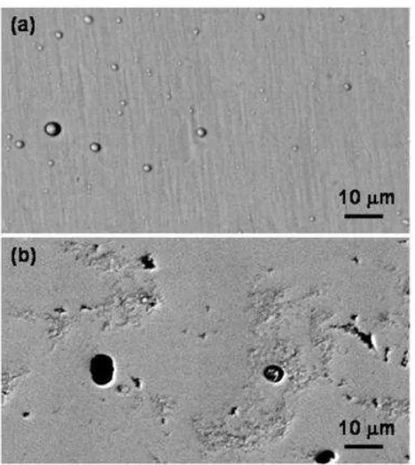
Fig. 2a shows a scanning back-scattered electron micrograph of as-deposited TiAlN/VN surface.
The surface morphology is featured by the presence of droplet-induced growth defects and
surface grooves. As a general phenomenon happening in acthodic arc, metal droplets were
emitted to reach and deposit on the substrate surface, each leading to a localized growth defect.
Meanwhile, the original roughness of the pre-polished substrate surface was modified as a result
of the applied metal ion etching. Consequently, the grooves observed on the coating surface
resulted from the preferential etching of the substrate steel. The applied bias voltage during the
coating deposition also played a role in determining the surface roughness, which has been
characterized by atomic force microscopy and cross-sectional TEM [22]. In Fig. 2b, the worn
surface is even smoother than the as-deposited coating owing to the removal of defects and
surface grooves. More importantly, the worn surface, even in the areas of the preferential wear of
the droplet defects (see the black holes in the image), does not show any crack or visible
delamination wear. More details of the friction and wear property can be found in ref. [23].
A pair of TEM BF and DF micrographs (Figs. 3a and 3b) show the cross-sectional structure of
the worn TiAlN/VN coating. The upper part in the micrographs, marked as ‘I’ in the
micrographs, is a portion of the copper re-deposit resulted from the ion beam milling, which has
edge where a tribofilm (marked as ‘II’) can be seen to show a thickness ranging in 20 – 40 nm
and a clear boundary to the adjacent TiAlN/VN coating (marked as ‘III’), seen at higher
magnification in Fig. 3c. The tribofilm seems to be more transparent than the adjacent
TiAlN/VN. It is amorphous, as its convergent beam electron diffraction showed only a
transmission (central) spot and it exhibited a constantly ‘grey’ diffraction contrast (Figs. 3a and
3b) not changing with sample tilting. In the area exactly below the tribofilm, the TiAlN/VN
coating retains its regular multilayer fringes, see Fig. 3c. The curvature in the multilayer fringes
was attributed to the applied low substrate bias voltage (-75V) which led to a rough growth
surface [22]. In previous research, we have found that worn surface deformation induced by high
load and high friction in sliding wear leads to crack generation and delamination wear of
transition metal nitride coatings like TiN, TiAlCrN and TiAlN/CrN. However, the TiAlN/VN
coating presented in this work exhibits no measurable deformation up to the instrumental spatial
resolution of TEM, no occurrence of crack or delamination wear.
Fig. 4 shows typical EDX spectra taken at a spot size of 15 nm in nominated diameter in the
following areas: (a) copper re-deposit layer, (b) tribofilm, (c) wear debris (to be shown later in
Fig. 5), (d) TiAlN/VN coating close to the worn surface, and the VN base layer (image not shown
here but given in ref. [22]). The spectrum taken in the re-deposit layer indicates merely the
sputtered material from the copper grid and sample substrate. The spectrum from the tribofilm
area shows high intensity peaks of V-Kα (4.95 keV), Ti-Kα (4.51 keV) and Al-Kα (1.49 keV), and
a small but distinct peak O-Kα. It is also noted that the N-Kα channel (0.39 keV) locates exactly at
the valley position. In addition, there are overlaps of the V-Kα with the Ti-Kβ (4.932 keV) and of
the O-Kα with V-Lα (0.51 keV). The Cu peaks are due to sample drift to the adjacent copper layer
because of the extremely small thickness of the tribofilm, 20 – 40 nm. Similar results are
obtained in the wear debris. Thus the tribofilm and wear debris are predominately a mixture of
peaks V-Kα, Ti-Kα and Al-Kα, and a distinct peak N-Kα. An example spectrum collected in the
VN base layer is also given for the purpose of V-Lα/Kα ratio calibration.
The TEM-EDXS qualitative analysis indicates that the tribofilm is predominately a mixture of
oxide and the coating adjacent to the tribofilm has kept the TiAlN/VN composition containing
negligible oxygen. In previous research, we have found that the iso-thermal oxidation of a TiAlN
based multicomponent coating led to the formation of a 50 nm thick transition layer where nitride
transformed progressively to oxide [25]. This is clearly not the case in the tribo-oxidation. Figs. 3
and 4 suggest that a sharp boundary exists between the tribofilm and the TiAlN/VN without any
detectable intermediate layer.
Spectrum quantification has been carried out for the EDXS results obtained in the tribofilm and
the adjacent TiAlN/VN respectively, Tables 1 and 2. The average compositions are determined
from four to five measurements as presented. In Table 1, the average composition of the
TiAlN/VN coating was determined to be 15.9 at%Al, 15.3 at%Ti and 18.8 at%V assuming a
stoichiometric content of nitrogen (50 at%N). In Table 2, the chemical composition of the
tribofilm was determined to be 36.8 at%O, 19.6 at%Al, 19.9 at%Ti and 23.8 at%V. The oxygen
content is however, of lower precision because of the large scattering in the oxygen content
(between 24.3 at% and 46.1 at%, giving a standard deviation 9.8 at%) due to the un-corrected
absorption of both O-Ka and V-La. The real oxygen content could be even higher. Nevertheless, the composition reveals considerable amount of oxygen and co-existence of Al, Ti and V,
indicating a multi-component oxide mixture V-Al-Ti-O. In particular, it exhibits similar
metal-to-metal ratios, i.e. Al:Ti = 0.98 and V:Ti = 1.19, as compared to the TiAlN/VN (being 1.04 and
1.22 respectively).
From Tables 1 and 2, it is noticed that the tribofilm emitted substantially lower intensity and
coating (e.g. V-K = 5308 380 counts). Noting the identical acquiring conditions applied in
both areas, the lower intensity suggests significantly lower mass density in the tribofilm. In TEM
imaging, an area of low mass density is expected to give high brightness in zero-loss imaging or
bright-field imaging due to less amount of inelastic electron scattering. This has been confirmed
in Fig. 3 which shows brighter contrast in the tribofilm area than the adjacent TiAlN/VN. The
data scattering of K peaks in Table 2 might further imply that the tribofilm is inhomogeneous to
nano-scale.
Fig. 5 shows TEM analyses of TiAlN/VN wear debris. In Fig. 5a, the bright field micrograph
shows clusters of amorphous debris. The amorphous structure is also revealed by the broad
diffusive rings in the SAED pattern, Fig. 5b. In addition, the three distinct diffraction rings in Fig.
5b suggests that crystalline α-Al2O3 particles exist in the debris as a result of the wear of the
alumina counterpart. However, the wear coefficient of the counterpart, Kball = 4 10-19 m3·N-1·m-1
[23], is so small that accounted for only 1.8% that of coating (Kcoat = 2.3 10-17 m3·N-1·m-1).
Therefore the majority of the wear debris comes from the wear of the coating. A typical EDX
spectrum of the wear debris is shown in Fig. 4. By carefully identifying the energy channel
position of N-K and O-K, it has been found that O-K dominated the intensity peak and N-K
position is close to the valley. The debris is consequently considered to be free from nitrogen,
which means that non-detectable amount of nitrides indicate negligible mechanical wear of the
coating. More details of the EDXS analysis results are shown in Table 3. The composition of the
wear debris was determined to be 44.9 at%O, 17.2 at%Al, 17.6 at%Ti and 20.3 at%V. This is
close to the composition of the tribofilm as shown in Table 2.
The low friction coefficient of TiAlN/VN coating presented in Fig. 1 is consistent with our
previous research [1, 2, 23]. Low friction resulted in a smooth and delamination-free worn
surface (Fig. 2). Innovative contribution in this paper is the cross-sectional TEM presentation and
characterization of a nano-scale oxide film on the worn surface.
The observed tribofilm is 20 – 50 nm thick, amorphous and closely attached to the TiAlN/VN
with a distinct interface, Fig. 3. The tribofilm is almost free of nitrogen and exhibits a chemical
composition of 36.8 at%O, 19.6 at%Al, 19.9 at%Ti and 23.8 at%V, Table 2. In parallel, good
agreement can be seen between the tribofilm and wear debris except the uncertainty in oxygen
content. The current EDXS results suggest that the tribofilm and wear debris are mainly
generated from the wear of the coating although the debris did show the presence of Al2O3 nano-particles. Such tribofilm is different from the film generated in the wear of TiN and TiAlN based
coatings sliding against a steel counterpart where the tribofilm and debris were both
nano-crystalline iron oxides [9, 26, 27]. Similar amorphous structures in wear debris or in tribofilms
have been reported in ref. [16, 17, 27]. Although the oxygen content determined is still in low
precision, the results presented have suggested that EDXS analysis on ion-beam milling thinned
TEM foil is an appropriate method to distinguish light elements like oxygen and nitrogen,
especially when locating the electron probe close to the extremely thin edge.
A schematic diagram (Fig. 6) can be drawn to show the formation of tribofilm. As soon as wear
debris is generated, it is involved in the sliding wear by forming a tribofilm between the
contacting surfaces. The tribofilm reported in this study neither has a crystalline structure as
compared to the annealing induced oxides of TiAlN/VN [13, 14], nor contains crystalline V2O5 as reported in previous Raman microscopy study [10]. However, it really resulted in a three-body
system: the counterpart, tribofilm and the coating. In particular, the amorphous structure revealed
that the tribofilm would have experienced severe shear straining in each pass of the pin-on-disc
determined the low-value and stable friction coefficient of the TiAlN/VN. A deeper
understanding of the composition and ionic structure is proposed, for example, by electron energy
loss spectroscopy study. Nevertheless, it is indicated that a low friction coefficient favours low
rate of tribo-oxidation wear. In literature [28], the friction induced bulk temperature and flash
temperature in dry sliding wear of metals were described to increase linearly with increasing
friction coefficient. Therefore in the current experiments, the low friction coefficient of
TiAlN/VN ( = 0.4) is expected to lead to low increase of temperature within the sliding contact
zone as compared to the sliding wear of high-friction coating TiAlCrYN ( = 0.66 [23]). As a
temperature dependent process, the oxidation of the coating at the tribofilm-nitride interface
is
expected to be
an extremely slow process.In addition, the cross-section TEM observations confirmed good integrity of the TiAlN/VN
multilayer up to the outmost worn surface (Fig. 3) which forms a big contrast to our previous
observations of the wear induced deformation and coating delamination occurring in TiN,
TiAlN/CrN and TiAlCrYN coatings [8, 9, 26]. This implies a negligible amount of mechanical
wear.
5. Conclusions
In dry sliding wear tests, TiAlN/VN coatings deposited by cathodic arc metal ion etching and
unbalanced magnetron sputtering deposition have repeatedly shown low coefficients of friction
and wear. In this paper, results have been presented on TEM observation and associated EDXS
analysis of worn surface and wear debris, leading to the following conclusions.
A 20 – 50 nm thick tribofilm was observed on the TiAlN/VN worn surface. Both the tribofilm
V-Al-Ti-O composition. The tribofilm was formed through a self-sintering process of oxide wear
debris involved between the sliding surfaces.
Crystalline V2O5 oxide was not found on the worn surface or in the debris. Therefore, it was the multicomponent V-Al-Ti-O oxide, instead of the lubricious V2O5, which determined the low friction coefficient.
The major wear mechanism operating in the TiAlN/VN coating is the tribo-oxidation wear. The
TiAlN/VN worn surface exhibited good structural integrity without any crack, delamination or
detectable deformation, resulting in minimized mechanical wear.
The employed cross-sectional TEM and EDXS method on ion-beam thinned samples is capable
of observing nano-scale oxide film and distinguishing the light elements oxygen and nitrogen
References
[1] WD Münz, LA Donohue, PEh Hovsepian, Surf. Coat. Technol. 125 (2000) 269.
[2] PEh Hovsepian, DB Lewis, WD Münz, Surf. Coat. Technol. 133-134 (2000) 166.
[3] PEh Hovsepian, WD Münz, Vacuum 69 (2003) 27.
[4] Q Luo, G Robinson, M Pittman, M Howarth, WM Sim, MR Stalley, H Leitner, R Ebner, D
Caliskanoglu, PEh Hovsepian, Surf. Coat. Technol. 2005, to be published.
[5] JS Koehler, Phys. Rev. B2 (1970) 547.
[6] U Helmersson, S Todorova, SA Barnett, JE Sundgren, LC Markert, JE Greene, J. Appl. Phys.
62 (1987) 481.
[7] SA Barnett, M Shinn, Annu. Rev. Mater. Sci. 20 (1990) 245.
[8] Q Luo, WM Rainforth, WD Münz, Wear 225-229 (1999) 74.
[9] Q Luo, WM Rainforth, WD Münz, Scripta Mater. 45 (2001) 399.
[10] CP Constable, J Yarwood, PEh Hovsepian, LA Donohue, DB Lewis, WD Münz, J. Vac. Sci.
Technol. A18 (2000) 1681.
[11] PH Mayrhofer, PEh Hovsepian, WD Mitterer, Surf. Coat. Technol. 177-178 (2004) 341.
[12] A Erdemir, Tribo. Lett. 8 (2000) 97.
[13] DB Lewis, S Creasey, Z Zhou, JJ Forsyth, AP Ehiasarian, PEh Hovsepian, Q Luo, WM
Rainforth, WD Münz, Surf. Coat. Technol. 177-178 (2004) 252.
[14] Z Zhou, WM Rainforth, DB Lewis, S Creasey, JJ Forsyth, F Clegg, AP Ehiasarian, PEh
Hovsepian, WD Münz, Surf. Coat. Technol. 177-178 (2004) 198.
[15] A Erdemir, C Bindal, GR Fenske, Appl. Phys. Lett. 68 (1996) 1637.
[16] M Woydt, A Skopp, I Dorfel, K Witke, Wear 218 (1998) 84.
[17] A Blomberg, S Hogmark, J Lu, Tribo. Int. 26 (1993) 369.
[18] C Minfray, JM Martin, C Esnouf, T Le Mogne, R Kersting, B Hangenhoff, Thin Solid Films
[19] WM Rainforth, R Stevens, J Nutting, Phil. Mag. A66 (1992) 621.
[20] LA Donohue, WD Münz, DB Lewis, J Cawley, T Hurkmans, T Trinh, I Petrov, JE Greene,
Surf. Coat. Technol. 93 (1997) 69.
[21] DB Lewis, LA Donohue, M Lembke, WD Münz, Jr. R Kuzel, V Valvoda, CJ Blomfield,
Surf. Coat. Technol. 114 (1999) 187.
[22] Q Luo, DB Lewis, PEh Hovsepian, WD Münz, J. Mater. Res. 19 (2004) 1093.
[23] Q Luo, PEh Hovsepian, DB Lewis, WD Münz, YN Kok, J Cockrem, M Bolton, A Farinotti,
Surf. Coat. Technol. 193 (2005) 39.
[24] DB Williams, CB Carter, Transmission electron microscopy IV: Spectrosmetry. New York:
Plenum Press; 1996. p. 608.
[25] Q Luo, C Leyens, P Eh Hovsepian, D B Lewis, C P Constable, WD Münz, Oxidation
mechanism of PVD TiAlCrYN coating observed by analytical TEM, Electron Microscopy and
Analysis 2001, edt. M. Aindow and C.J. Kiely, Institute of Physics, 2001, p. 369.
[26] Q Luo, WM Rainforth, WD Münz, Surf. Coat. Technol. 146-147 (2001) 430.
[27] E de Wit, B Blanpain, BL Froyen, JP Celis, Wear 217 (1998) 215.
Table and figure captions
Table 1 The chemical composition of TiAlN/VN coating determined by quantitative TEM-EDXS
analysis. *The N content is assumed to be 50 at% for the stoichiometric nitride coating.
Table 2 The chemical composition of tribofilm determined by quantitative TEM-EDXS analysis.
Table 3 The chemical composition of wear debris determined by quantitative TEM-EDXS
analysis.
Fig. 1 Friction curve of TiAlN/VN coating.
Fig. 2 Back-scattered scanning electron micrographs of TiAlN/VN coating. (a) as-deposited
coating surface; (b) Worn surface after 200,000 laps of dry sliding against an alumina ball at 5N,
0.1 m∙s-1 .
Fig. 3 Cross-sectional TEM BF images of worn TiAlN/VN coating showing the copper
re-deposit (marked as region I), a tribofilm (region II), and the TiAlN/VN multilayer coating (region
III). (a) Low-magnification BF image; (b) Associated DF image; and (c) High-magnification BF
image.
Fig. 4 Typical EDX spectra obtained in the cross-section TEM sample. (a) In the copper
re-deposit; (b) In tribofilm; (c) In loose wear debris (see Fig. 5a); (d) In TiAlN/VN close to the
tribofilm; and (e) In the VN base layer.
Fig. 5 TEM analysis of wear debris: (a) a bright field micrograph and (b) a SAED pattern.
Fig. 6 Schematic graph showing the formation of tribofilm and its influence on the wear of
Tables
Table 1 The chemical composition of TiAlN/VN coating determined by quantitative TEM-EDXS analysis. *The N content is assumed to be 50 at% for the
stoichiometric nitride coating.
Peak integration [unit: counts] Estimated Composition [unit: at%]
Al-K Ti-K V-K N* Al Ti V
Range [keV]
1.33 – 1.61 4.33 – 4.69 4.75 – 5.13
Spectrum 1 2076 2475 4981 50 15.9 15.2 18.9
Spectrum 2 2144 2440 4879 50 16.5 15.0 18.5
Spectrum 3 2090 2768 5309 50 15.1 16.0 18.9
Spectrum 4 2392 2822 5652 50 16.1 15.2 18.7
Spectrum 5 2378 2793 5717 50 16.0 15.1 18.9
Table 2 The chemical composition of tribofilm determined by quantitative TEM-EDXS analysis
Peak integration [unit: counts] Estimated Composition [unit: at%]
O-K Al-K Ti-K V-K O Al Ti V
Range [keV]
0.39 – 0.65 1.33 – 1.61 4.33 – 4.69 4.75 – 5.13
Spectrum 1 740 730 889 1553 46.1 17.8 17.4 18.7
Spectrum 2 678 1021 1269 2717 42.7 17.2 18.4 21.7
Spectrum 3 710 729 977 1873 33.9 20.0 19.9 26.2
Spectrum 4 629 1524 1975 3811 24.3 23.2 24.0 28.5
[Mean] ± [deviation] 689 ± 47 1001 ±
374
1278 ±
493
2489 ±
1009
36.8 ±
9.8
19.6 ±
2.7
19.9 ±
2.9
23.8 ±
Table 3 The chemical composition of wear debris determined by quantitative TEM-EDXS analysis
Peak integration [unit: counts] Estimated Composition [unit: at%]
O-K Al-K Ti-K V-K O Al Ti V
Range [keV]
0.40 – 0.65 1.32 – 1.64 4.33 – 4.69 4.77 – 5.15
Spectrum 1 2535 2365 2667 5368 44.1 18.5 16.7 20.7
Spectrum 2 1660 1310 1638 3335 46.6 16.4 16.4 20.6
Spectrum 3 1519 1370 1547 2844 46.2 18.4 16.6 18.8
Spectrum 4 1266 1126 1526 2755 43.1 17.3 18.7 20.8
Spectrum 5 3631 2817 4460 7689 44.3 15.4 19.5 20.8
[Mean] ± [deviation] 2122 ±
Figure 3a / Figure 3b
[image:22.612.182.418.86.665.2]Figure 5a
[image:25.612.181.419.342.700.2]