Increasing Network Lifetime by Radio Wake-up
for Wireless Sensor Networks
Syeda Gauhar Fatima
1, Syeda Kausar Fatima
2, Abdul Aleem
31Professor ECE Dept, Deccan College of Engineering and Technology, Darussalam, Hyderebad. 2Research Scholar ECE dept. , JNTUH, Kukatpally, Hyderabad
3Assistant Professor ECE dept, Deccan College of Engineering and Technology, Darussalam, Hyderabad.
Abstract: A passive wake-up radio in a wireless sensor network (WSN) has the advantage of increasing network lifetime by using a wake-up radio receiver (WuRx) to eliminate unnecessary idle listening. A sensor node equipped with a WuRx can operate in an ultra-low-power sleep mode, waiting for a trigger signal sent by the wake-up radio transmitter (WuTx). The passive WuRx is entirely powered by the energy harvested from radio transmissions sent by the WuTx. Therefore, it has the advantage of not consuming any energy locally, which would drain the sensor node’s battery. Even so, the high amount of energy required to wake up a passive WuRx by a WuTx makes it difficult to build a multi-hop passive wake-up sensor network. In this paper, we describe and discuss our implementation of a battery-powered sensor node with multi-hop wake-up capability using passive WuRxs, called MH-REACH-Mote (Multi-hop-Range EnhAnCing energy Harvester-Mote). The MH-REACH-Mote is kept in an ultra-low-power sleep mode until it receives a wake-up trigger signal. Upon receipt, it wakes up and transmits a new trigger signal to power other passive WuRxs. We evaluate the wake-up range and power consumption of an MH-REACH-Mote through a series of field tests. Results show that the MH-REACH-Mote enables multi-hop wake-up capabilities for passive WuRxs with a wake-up range of 9.4m while requiring a reasonable power consumption for WuTx functionality. We also simulate WSN data collection scenarios with MH-REACH-Motes and compare the results with those of active wake-up sensor nodes as well as a low power listening approach. The results show that the MHREACH-Mote enables a longer overall lifetime than the other two approaches when data is collected infrequently.1
I. INTRODUCTION
A wireless sensor network (WSN) is composed of a set of sensor nodes, also known as motes, that monitor physical or environmental conditions, such as temperature, sound, or video. The sensor nodes form an ad-hoc network to transmit data to one or more data sinks in the network. A wireless sensor node is typically composed of various types of sensors to collect data, one or more processing units to handle the data collected, memory to store the data before transmission, a power source (frequently a battery), and a transceiver for wireless communications. Since most sensor nodes are battery powered, limited battery capacity can constrain the overall lifetime of the sensor network.
There are several methods proposed in the literature to extend the network lifetime of a WSN. Duty cycling is one of the most widely studied approaches, which schedules data reception, data transmission, and inactive sleeping periods at regular intervals. During its sleep periods, a node neither transmits nor receives data. This approach requires synchronization of adjacent sensor nodes, as successful communication depends on the transmitting and receiving sides to be active simultaneously. These synchronization activities incur overhead and result in idle listening, since the nodes regularly switch to the reception mode whether or not there is a communication destined to them. Both the overhead incurred and the resulting idle listening consume battery energy, reducing the lifetime of the node and hence the WSN.
Another approach to extending network lifetime is to use wake-up radios, which do not suffer from the idle listening of duty cycling radios, by utilizing an on-demand RF wakeup radio hardware. A sensor node with an RF wake-up radio receiver (WuRx) is kept in an ultra-low-power sleep mode, neither transmitting nor receiving data. A wake-up transmitter (WuTx) sends a trigger signal to begin data transmission. When the WuRx receives the trigger signal, it wakes up the mote from the sleep mode, bringing it into the active mode. Then, the mote begins data transmission. This ondemand wake-up eliminates the energy waste caused by the unnecessary idle listening and synchronization of duty cycling, albeit with the cost of additional wake-up hardware.
There are two types of wake-up receivers. Active wakeup receivers utilize energy from a battery. They have the advantage of better wake-up performance in terms of wake-up range and wake-up delay. However, active wake-up receivers consume energy from batteries, which are also used to power sensors and to transmit data. On the other hand, passive wakeup receivers are powered by energy harvested from the WuTx. A passive WuRx has the advantage of not using any energy from the battery. One caveat of this system is the limitation of the wake-up range due to the limitations in the WuRx’s ability to harvest enough energy to generate an interrupt for the MCU on the sensor node. Furthermore, as passive WuRxs are powered by harvested energy, the WuTx is generally designed to transmit as much energy as possible, in order to achieve a reasonably long wake-up range. This makes it difficult to build a multi-hop WSN featuring motes equipped with both a passive WuRx and a WuTx. Thus, passive wake-up sensor nodes are often used in applications with a mobile data sink that can transmit the large energy required for the WuTx. For example, applications such as air pollution monitoring in a city or meter data collection for a smart grid application require sensor nodes to collect data periodically, but this data must only be communicated when a mobile sink (e.g., a data mule [16]) takes place to collect the data.
In our previous work [1], we proposed a high efficiency passive wake-up radio receiver called REACH-Mote, which utilizes an energy harvesting module and an ultra-low-power wake-up pulse generator to increase the passive wake-up range. We characterized the performance of the REACHMote and compared the performance of the REACH-Mote with other passive wake-up radio approaches, specifically the WISP-Mote [2] and the EH-WISP-Mote [1]. In this paper, we propose a sensor node equipped with both a passive WuRx and a WuTx. We name this new mote the MH-REACH-
Mote (Multi-hop-Range EnhAnCing energy Harvester-Mote). The MH-REACH-Mote can wake up other REACH-Motes and other MH-REACH-Motes, creating a multi-hop passive wake-up network. The MH-REACH-Mote is composed of: a Tmote-Sky sensor node; a passive wake-up receiver identical to REACH-Mote’s WuRx; and an RFID reader by AMS as the WuTx [3]. We adjust the duration of the wake-up signal sent by the WuTx to evaluate the achieved wake-up distance versus the corresponding energy cost. These field tests show that an MHREACH-Mote can wake up other REACH-Motes and MHREACH-Motes at a reasonable distance using only a small amount of energy, enabling the creation of a multi-hop wakeup network with passive WuRxs. In order to determine the benefit of a multi-hop wake-up network with passive WuRxs, we compare the performance in terms of energy consumption of an MH-REACH-Mote with the performance of a 65µW active wake-up sensor node [8] as well as the performance of a low power listening approach used for very low duty-cycle operation [4].
The remainder of this paper is organized as follows. In Section II, we present a survey of related work. The description of the hardware design of the MH-REACH-Mote is provided in Section III. Section IV presents results from field experiments. Section V evaluates the energy performance of different settings of the REACH-Mote and compares the energy performance of the MH-REACH-Mote with an active wakeup sensor node and a low power listening (LPL) approach. Conclusions are drawn in Section VI.
II. RELATED WORK
A. Single-hop Wake-up Radio Studies
An active WuRx with access to a power source is capable of using active components to increase its wake-up range. Since the WuRx is constantly listening for a wake-up signal, the energy consumption of the radio must be minimized, as to avoid greatly shortening the lifetime of the node equipped with this WuRx. Several studies have explored the use of active WuRxs, such as [5] and [6], which focus on decreasing the energy consumption of the baseband part of the WuRx. Other designs, such as [7] and [8], focus on building a complete solution for the WuRx and hence can operate at very low power, e.g., 123µW [7] and 65µW [8]. However, in situations where data transmissions only occur infrequently, an active WuRx requires a large amount of energy during the idle/sleep period of the node, which decreases the node lifetime.
B. WuRx Usage in Multi-Hop Enabled WSNs
Some recent research has focused on WuRx usage in multihop WSNs. However, only a few active WuRx studies present results drawn from WuRx hardware implementations. The research involving passive WuRx usage in multi-hop WSNs is based on theory and simulations. For example, Zhang et al. [10] focus on active wake-up, and build a multi-hop wakeup WSN equipped with a 123µW WuRx. The use of a
WuRx over a duty-cycling system improves the latency and lifetime of a multi-hop enabled WSN [10]. Ruzzelli et al. [11] propose a multi-hop WSN capable of using RFID readers and tags to achieve radio wake-up. However, the evaluation concentrates primarily on simulation results, and does not include any results from hardware implementations. To the best of our knowledge, the MH-REACH-Mote is the first reported complete implementation of a multi-hop passive radio wake-up device equipped with both a WuTx and a passive WuRx. All characterization data for the Mote is obtained using our implemented MH-REACH-Mote through field tests.
III. HARDWARE IMPLEMENTATION OF THE MH-REACH-MOTE AND A MULTI-HOP PASSIVE WAKE-UP
SENSOR NETWORK
A. MH-REACH-Mote
Although any sensor node device with an MCU with lowpower modes can be used, we used the Tmote-Sky platform to build the multi-hop wake-up sensor node (MH-REACH-Mote). The Tmote-Sky consumes very low energy while sleeping, which helps to conserve battery power and extend the node’s lifetime. The Tmote-Sky can be woken up from sleep by a
[image:3.595.199.399.442.573.2]Fig. 1.Block diagram of the MH-REACH-Mote.
Fig. 2. Hardware of the MH-REACH-Mote. rising/falling edge triggered by the passive WuRx, as described in [1].
In order to achieve multi-hop wake-up, the MHREACH-Mote must also include a WuTx component that can be triggered by the Tmote-Sky, e.g., through the Tmote-Sky’s digital I/O pins to control the WuTx’s activity. The entire sensor node requires only one power source, shared by the Tmote-Sky and the WuTx. Due to this approach, it is necessary to use energy judiciously in both the Tmote-Sky and the WuTx to optimize the sensor’s lifetime.
Several desired characteristics were considered in the design and creation of a complete sensor node, equipped with both a WuTx and a passive WuRx, including: • A sensor node must be able to be reliably woken up from sleep by its WuRx responding to a wake-up signal.
1) A 3V battery must power the entire sensor node. Since the Tmote-Sky uses two AA (1.5V ) batteries, ideally the WuTx should share this 3V source. • The WuTx must be able to be controlled by the Tmote-Sky.
3) The WuTx must be very energy efficient, in order to maximize the wake-up range without significantly decreasing the node’s battery level.
4) The WuTx may not need to send any address or implement security, but its design ideally will not prohibit a secure, addressable passive wake-up radio system from being implemented in the future.
We selected the AMS AS3992 UHF RFID Reader as the WuTx for the sensor node [12], as this is a low power, single chip solution. Moreover, it provides the option of building an addressable wake-up radio solution based on an RFID protocol, leaving the door open for the implementation of a secure, addressable passive wake-up radio system. This WuTx is controlled by the Tmote-Sky through a TI TPS2560DRC switch [13]. We combine the Tmote-Sky, the AS3992 board, and the REACH-Mote’s WuRx [1] to build the new sensor node, MH-REACH-Mote, equipped with both a WuTx and apassive WuRx. Fig. 1 shows a block diagram of this MHREACH-Mote, and Fig. 2 shows the hardware components of the MH-REACH-Mote.
B. Multi-hop Passive Wake-up Sensor Network
Each node in our multi-hop passive wake-up sensor network can function either as a multi-hop node, which sends a wakeup signal to wake-up other nodes, or as an edge node, which does not send a wake-up signal as no other node is located in its wake-up range. Each node must determine periodically whether it is a multi-hop node or an edge node in order to determine whether or not to transmit a wake-up signal once it is woken up by the sink or by another node in the network.
All nodes in our multi-hop passive up sensor network remain in the sleep mode, with the passive WuRx scanning for a wake-up signal. A mobile sink (or other designated node) provides the initial wake-wake-up in our system. As the sink goes by an area of the network, the WuTx on the sink wakes up all nodes in the vicinity of the sink. Any node that was woken up by the sink sends its data to the sink, and, if it is a multi-hop node, it also transmits a wake-up signal to wake up other nodes in its wake-up range. If it is an edge node, after transmitting its data to the sink, it returns to the sleep state until the next wake-up event.
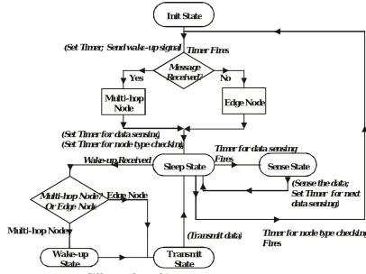
Specifically, the protocol run by the nodes is as follows: • When first deployed, an MH-REACH-Mote powers up and goes into the initialization, or Init, state.
1) In the Init state, the MH-REACH-Mote transmits a wakeup signal through its WuTx, attempting to wake up nearby nodes. A timer is set to fire at the end of the wake-up signal transmission period. Simultaneously, the radio on the Tmote-Sky is set to receiving mode, and listens for incoming messages. If a packet is received before the timer fires, the MH-REACH-Mote is defined as a multihop node. Otherwise, it is defined as an edge node. Note that although an edge node might not have any other node in its wake-up coverage, it might be in another node’s wake-up coverage due to the directorial antennas used.
2) Next, the MH-REACH-Mote sets a timer for data sensing and enters into the sleep state.
3) The MH-REACH-Mote will remain in the sleep state until either the timer for sensor data fires, or it receives a wakeup signal from its WuRx.
4) When the timer for sensor data fires, the MH-REACHMote enters into the sense state, and collects and stores the new data in memory. The MH-REACH-Mote then returns back to the sleep state.
[image:4.595.204.407.577.729.2]5) When the MH-REACH-Mote receives a wake-up signal from its WuRx, it enters into the wake-up state if the MH-REACH-Mote is a multi-hop node. Otherwise, if the MH-REACH-MH-REACH-Mote is an edge node, it enters directly into the transmit state.
Fig. 3.State diagram of the MH-REACH-Mote operation. Init State
Set Timer; Send wake-up signal
( )
Sense State Message
Received? No
Multi-hop Node? Or Edge Node
Yes
Wake-up State
) Wakes up other nodes (
Multi-hop Node
Edge Node
Trans mit State Sleep State
Timer Fires
Multi-hop
Node Edge Node
Set Timer for data sensing
( )
Set Timer for node type checking )
( Timer for data sensing
Fires Wake-up Received
( Sense the data; Set Timer for next data sensing)
6) An MH-REACH-Mote that entered into the wake-up state transmits a wake-up signal through its WuTx to wake up other MH-REACH-Motes. Then, the MH-REACH-Mote enters into the transmit state.
7) An MH-REACH-Mote in the transmit state will send its own stored data to the sink. We assume that if a node is woken up, it is in the transmission range of the sink, and hence the communication is direct from the node to the sink. After sending the data, the MH-REACH-Mote returns to the sleep state.
8) In dynamic topology scenarios, the node can return to the Init state periodically to see if it should change its type between multi-hop and edge node.
Fig. 3 shows the state diagram of the MH-REACH-Mote operation.
IV. EXPERIMENTS
We developed the MH-REACH-Mote prototype that is illustrated in Fig. 2. Here, we evaluate the wake-up coverage as well as the energy cost of the MH-REACH-Mote based on field tests of this prototype.
A. Characterization of Wake-up Range and Energy Consumption for the MH-REACH-Mote
We performed two sets of field tests to evaluate the wake-up coverage area of the MH-REACH-Mote. In the first set of tests, two MH-REACH-Motes were placed 60cm above the ground in an indoor environment. Both the transmitting node and the receiving node were connected to a S9028PCR circular polarity RFID panel antenna with a gain of 9dBiC [14], where dBiC (isotropic circular) is the forward gain of an antenna compared to a circularly polarized isotropic antenna [15]. We measured the maximum wake-up range with different durations of wake-up signal transmissions, varying from 30ms to 10s. 30ms is the time for a Tmote-Sky to transmit 12 bytes of data. Hence, the MH-REACH-Mote can use the time when it is performing data transmission to simultaneously transmit the wake-up signal.
A longer wake-up signal transmission provides more energy to the receiving node and does achieve a slightly longer wakeup range. However, this comes at the cost of increased energy consumption at the transmitting node, due to the extended time
WAKE-UP RANGE AND ENERGY CONSUMPTION FOR DIFFERENT WAKE-UP SIGNAL DURATIONS
Wake-up Signal Duration
30ms 100ms 500ms 1s
Wake-up Range (m)
8.8 8.8 8.8 8.8
Energy
Consumption (J)
0.11 0.29 1.35 2.41
Wake-up Signal Duration
2s 3s 5s 10s
Wake-up Range (m)
8.8 9.1 9.1 9.4
Energy
Consumption (J)
4.66 7.36 12.54 23.54
the wake-up signal is being sent. The purpose of this set of tests was to characterize the relationship between the duration of the wake-up signal transmission and the wake-up range.
Table I shows the maximum wake-up range and the energy consumed by the MH-REACH-Mote for different wake-up transmission durations in the first set of field tests. The measurements shown correspond to the average of three sets of measurements with a variance less than 15cm. The results show that the maximum wake-up range is 9.4m, achieved when the wake-up signal was transmitted for 10 seconds. Even when the MH-REACH-Mote is only turned on for 30ms, which costs only 0.11J
trade-off for many applications. However, for applications that require the maximum wake-up range, the node lifetime may be traded off to achieve an extended wakeup range.
B. Performance of MH-REACH-Mote in a Multi-Hop Network
We perform the second set of field tests to evaluate the multi-hop performance of the MH-REACH-Mote when it cooperated with a mobile base-station moving along a predefined path. This is a realistic scenario such as when a car, which acts as a data mule [16], drives along the road and wakes up the sensor nodes deployed on the side of the road (e.g., on mailboxes, on street signs, etc.). After a sensor node along the side of the road is woken up, it transmits a signal to wake up the other nodes located further away (e.g., on a house or building nearby). Then, all nodes send the data to the data mule.
[image:6.595.196.430.283.442.2]The base-station we used was a combination of an Impinj RFID reader [17] and a Powercast energy transmitter [18]. Based on our previous work [1], the WuRx on a REACH-Mote can be triggered at a distance of 11.2m from the base-station within 120 seconds. In order to ensure a quick wake-up, we deployed the MH-REACH-Mote 10.6m from the moving path of the base-station to ensure a stable and quick wake-up within
Fig. 4. Multi-hop wake-up coverage with base-station assistance. 5 seconds. In this field test, the mobile base-station moves along the path to wake up the first MH-REACH-Mote when it comes close to it. After this MH-REACH-Mote is woken up, it acts as a multi-hop node and wakes up a second, farther MHREACH-Mote. As the base-station can continuously transmit energy, this can pre-charge the WuRx on the second-hop MHREACH-Mote before the first-hop MH-REACH-Mote starts transmitting the wake-up signal. Thus, the base-station can potentially improve the wake-up range of the second-hop MHREACH-Motes.
Fig. 4 shows the wake-up range results of the second set of field tests, where the second MH-REACH-Mote is placed in different locations to test the wake-up range of the secondhop. In this test, the mobile base-station moves towards the direction indicated in Fig. 4, transmitting a wake-up signal along its path. An MH-REACH-Mote along the moving path of the base-station is woken up by the base-station and transmits a wake-up signal with a constant duration of 30ms to wake up a second MH-REACH-Mote. As the wake-up signal received by the WuRx is a combination of the signal transmitted by the MH-REACH-Mote and the base-station, we expect the wake-up range can get extended in this scenario. We evaluate the performance of wake-up coverage of this 2-hop passive wake-up sensor network. We found that the maximum wake-up range between the first hop MH-REACH-Mote and the second hop MH-REACH-Mote is 10.3m, which represents a 1.5m (17% improvement) increase with the assistance of the base-station compared to the previous result with a 30ms wake-up signal. This result is achieved when the base-station and two MH-REACH-Motes are all aligned in a straight line. Additionally, with the assistance of the base-station, the wakeup range is always found to be above 9.4m. This minimum wake-up range of 9.4m corresponds to the case when the base-station is horizontally aligned with the first MH-REACHMote, and the second MH-REACH-Mote is vertically aligned with the first one.
C. Analysis of MH-REACH-Mote Lifetime
In order to evaluate the potential lifetime of the MHREACH-Mote, we measure the current consumption of the
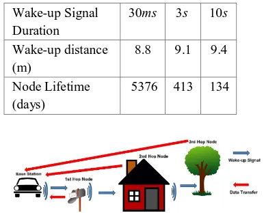
ranges. As shown in Table II, since a wake-up range of 8.8m only requires the WuTx to be transmitting the wake-up signal for 30ms, the node can remain operational for more than 5000 days, achieving a lifetime of more than 14 years. However, as the wake-up range requirements increase, the node lifetime decreases dramatically. If a node needs to achieve a wake-up range of 9.4m, the node lifetime decreases to 134 days, which may still be an acceptable node lifetime for some applications. Note that the energy cost of the data sensing as well as the battery leakage are ignored in evaluation.
Wake-up Signal Duration
30ms 3s 10s
Wake-up distance (m)
8.8 9.1 9.4
Node Lifetime (days)
[image:7.595.210.403.188.344.2]5376 413 134
Fig. 5.Working scenario for MH-REACH-Mote.
Fig. 6.Working scenario for active wake-up.
Fig. 7.Working scenario for low power listening approach.
V. LIFETIMES FOR MH-REACH-MOTES, ACTIVE WAKE-UP MOTES AND A LOW POWER LISTENING
APPROACH
Fig. 8.Operation of the low power listening protocol.
For the active wake-up radio network scenario, the nodes are also in the sleep mode most of the time. However, during this time in the sleep mode, the active WuRx is dissipating a constant 65µW. The mobile car sends a wake-up signal along the road, which wakes up all three sensor nodes on the mailbox, house and trees. After the sensor nodes are woken up, they send their data to the mobile car. Fig. 6 shows the working scenario for this active wake-up.
Fig. 8 shows the communication protocol for the low power listening (LPL) scenario we evaluated. The base station continuously sends a long preamble while driving along the road. The preamble lasts for 300ms, followed by a 30ms gap in order for the base station to listen for a response packet sent from the sensor nodes. All nodes are kept in the sleep mode most of the time, and they wake up for 5ms periodically according to an internal sleep timer T to listen for the preambles and check if the base station is located within their communication range. If the node wakes up and the base station is located within its communication range, like LPL Sensor Node 1 in Fig. 8, the node sends its data to the base station and goes back to sleep. Otherwise, the sensor node goes back to sleep for 30ms and listens to the channel again for the possibility that the first listening coincided with the gap between two preambles, as with LPL Sensor Node 2 in Fig. 8. If the base station is located within the communication range of the sensor node, this approach can guarantee a wake-up. If the sensor node does not receive a preamble in either of these two listening intervals, the sensor node goes directly back to sleep for a time T.
The value of the sleep timer T should ensure a successful wake-up whenever the mobile base station is passing by the sensor node. As the Tmote-Sky sensor node can achieve a 125m outdoor communication range [20], the speed of the base station determines the maximum period T. The two different speeds of the mobile base station we evaluated are 10m/s and 20m/s. Thus, the sleep timer T
should be less than 25 and 12.5 seconds. In our evaluations, we considered the case of 25 and 12.5 seconds, respectively.
Energy Consumption For Components Of The Mh-Reach-Mote, An Active Wake-Up Radio Mote [8] And An Lpl Mote [4]
Operation Average current
consumption
Duration
Tmote-Sky transmit 12
byte packet 18.35mA 30ms
Tmote-Sky in sleep mode 11.2µA Continuous
MH-REACH-Mote send
wake-up signal 1.25A 30ms
Current leakage of TI
TPS2560DRC switch
0.1µA Continuous
Wakeup for 5 ms and
listen for preamble
30 ms
Wait Until
Preamble End
Data Transmission
and go back to sleep Base Station
LPL Sensor Node 1
LPL Sensor Node 2
Base Station Preamble 300ms
Wakeup but
missed preamble
30 ms
30 ms
30ms
30 ms
Sleep for 30ms
and listen for
preamble again
Wakeup
and listen
for preamble
30ms
Wait Until
Preamble End Data
Transmission Preamble 300ms
[image:8.595.86.523.597.746.2]Fig. 9. Comparison of node lifetime using an MH-REACH-Mote, an active wake-up radio mote [8] and a low power listening sensor node.
For all three of these scenarios, we assume:
1) No collisions occur during the data transmission.
2) All sensor nodes are located within the communication range of the data sink.
3) All sensor nodes in the active wake-up scenario are located within the wake-up range of the data sink.
4) All nodes return to the sleep mode once they finish their data transmissions.
5) The data sink does not have any energy constraints.
6) Each node is powered by 2 AA batteries with 1800mAh energy.
Table III shows the energy consumption of the different components of the MH-REACH-Mote, the active wake-up radio mote [8] [13] and the LPL mote.
Fig. 9 shows the network lifetime for different intervals between when the base station collects data. As the TI TPS2560DRC switch on the MH-REACH-Mote’s WuTx only leaks 0.1µA from the battery during the sleeping period [13], the MH-REACH-Mote can achieve much higher energy efficiency compared to the active WuRx approach as the interval between two wake-up events increases. The MHREACH-Mote can achieve longer lifetime than active wakeup for average intervals between successive base station data collections of 30 minutes or more, which is a common scenario for a sensor network with regular data collection such as daily or even weekly temperature/moisture data collection and air pollution monitoring.
[image:9.595.159.410.581.714.2]This observation also applies to the low power listening approach. For every 25 or 12.5 seconds, the sensor node will wake up from sleep state and check if the base station is close by. If the base station is not within the communication range, this process will waste 0.5505mJ energy. This low power listening strategy wastes a lot of energy for unnecessary wakeups especially for longer interval arrival times of the base station. As this low power listening approach does not have continuous energy consumption except for the 11.2µA current draw in sleep mode, this approach consumes less energy than the 65µW active wake-up and results in longer lifetimes compared to active wake-up. As this approach periodically wastes energy on listening for the channel, a huge amount of energy is wasted if the communication between base station and sensor node occurs infrequently. Thus, the MH-REACHMote can achieve better energy efficiency than this low power listening approach for average intervals between successive base station data collections of 2 hours or more.
Fig. 10. Comparison of energy overhead of an MH-REACH-Mote, an active wake-up radio mote [8] and a low power listening sensor node.
MH−REACH−Mote
LPL Protocol (BaseStation Speed 10m/s) LPL Protocol (BaseStation Speed 20m/s)
65uW Active Wakeup
Wake-up Interval
Further increasing the interval between successive data collections to a week extends the network lifetime of MHREACH-Mote to 6600 days, which represents almost three times the network lifetime of the active wake-up radio sensor network and 50% longer lifetime compared to the low power listening approach. As the energy cost of the data sensing as well as the battery leakage are ignored in the calculation, the actual lifetime for nodes in the application could be potentially less than this calculation. Also, we notice that the increasing rate of the node lifetime goes down with an increase in the wake-up interval for longer wake-up intervals. This is because a greater portion of the energy is consumed by the Tmote-Sky during the sleep period when the wake-up interval is long. As the network lifetime is affected by the energy consumption of the Tmote-Sky, we also evaluate the average overhead costs for the different approaches. For the MH-REACH-Mote, the WuTx and the TI TPS2560DRC switch are the main sources of overhead energy consumption. For the 65µW active wake-up sensor node, the energy cost for the active wake-up circuit (WuRx) dominates the energy overhead cost. For the low power listening sensor node, the unnecessary wake-ups to probe the channel are the key energy overhead. Thus, we evaluate the energy overhead for these three approaches. The results are shown in Fig. 10, which does not include the energy cost of the Tmote-Sky in transmitting data and sensing. The results show that the WuTx circuit on the MH-REACH-Mote consumes less energy than that of the active wake-up receiver for successive data collections of 30 minutes and longer. the low power listening sensor node wastes less energy than the active wake-up receiver. However, it costs more energy than the MH-REACH-Mote for intervals of 1 hour and longer. Also, we find that increasing the moving speed of the base station increases the energy waste for the low power listening approach. If the interval between successive data collections is a week, the average energy cost of the MH-REACH-Mote’s WuTx circuit decreases to as low as 0.04J/day, which is about 140 times less than that of the active wake-up radio mote and about 45 times less than that of the low power listening mote.
VI. CONCLUSIONS AND FUTURE WORK
In this paper, we proposed the MH-REACH-Mote to build a multi-hop passive wake-up sensor network. Experimental results show that the MH-REACH-Mote can achieve a reasonable wake-up range of 9.4m. Also, with the assistance of the base-station, an MH-REACH-Mote can achieve a 10.3m wake-up range with low energy consumption, which makes the MH-REACH-Mote a robust candidate for applications with long idle intervals between data transmission. As future work, we plan to design a new network protocol for a WSN composed of MH-REACH-Motes and evaluate the performance of this multi-hop passive wake-up network.
VII. ACKNOWLEDGEMENT
The authors thank Mr. Pak Lam Yung for his help in collecting data for the base-station assisted field tests.
REFERENCES
[1] Chen, L., Cool, S., Ba, H., Heinzelman, W., Demirkol, I., Muncuk, U., Chowdhury, K., and Basagni, S., ”Range Extension of Passive Wake-up Radio Systems through Energy Harvesting,” ICC 2013, Jun. 2013.
[2] Ba, H., Demirkol, I. and Heinzelman, W., ”Feasibility and Benefits of Passive RFID Wake-up Radios for Wireless Sensor Networks,” GLOBE-COM 2010, Dec. 2010
[3] http://www.ams.com/eng/Products/RF-Products
[4] Merlin, C., Heinzelman, W., ”Duty Cycle Control for Low-Power-Listening MAC Protocols,” IEEE Trans. on Mobile Computing, Nov. 2010
[5] Zhang, Y., Chen, S., Kiyani, N. F., Dolmans, G., Huisken, J., Busze, B., Harpe, P., van der Meijs, N., De Groot, H., ”A 3.72µW ultra-low power digital baseband for wake-up radios,” VLSI-DAT 2011, Apr. 2011
[6] Harpe, P., Huang, X., Wang, X., Dolmans, G., De Groot, H., ”A 0.37µW 4bit 1MS/s SAR ADC for ultra-low energy radios,” VLSI-DAT 2011, Apr. 2011 [7] Huang, X., Harpe, P., Dolmans, G., De Groot, H., ”A 915MHz ultra-low power wake-up receiver with scalable performance and power consumption,”
Proceedings of the ESSCIRC 2011, Sept. 2011
[8] Pletcher, N., Gambini, S., Rabaey, J., ”A 65µW, 1.9 GHz RF to Digital Baseband Wakeup Receiver for Wireless Sensor Nodes,” CICC 2007, Sept. 2007 [9] Ba, H., Demirkol, I., Heinzelman, W., ”Passive wake-up radios: From devices to applications,” Ad Hoc Networks, Nov. 2013
[10] Zhang, Y., Dolmans, G., ”Wake-up radio assisted energy-aware multihop relaying for low power communications,” WCNC 2012, April 2012
[11] Ruzzelli, A., Jurdak,R., O’Hare, G., ”On the RFID wake-up impulse for multi-hop sensor networks,” ACM International Conference on Embedded Networked Sensor Systems, November 2007
[12] http://www.ams.com/eng/Products/RF-Products/RFID/AS3992 [13] www.ti.com/lit/ds/slvs930a/slvs930a.pdf
[14] http://www.lairdtech.com/ [15] http://en.wikipedia.org/wiki/Decibel
[16] Shah, R. C., Roy, S., Jain, S., Brunette, W., ”Data MULEs: Modeling a Three-tier Architecture for Sparse Sensor Networks,” Intel Research Tech Report , January 2003
[17] http://www.impinj.com/Speedway Reader Family.aspx [18] http://www.powercastco.com/products/powercastertransmitters/ [19] http://www.ece.rochester.edu/projects/wcng/project genius2.html
![Fig. 2. Hardware of the MH-REACH-Mote. rising/falling edge triggered by the passive WuRx, as described in [1]](https://thumb-us.123doks.com/thumbv2/123dok_us/1244012.650651/3.595.199.399.442.573/hardware-reach-mote-rising-falling-triggered-passive-described.webp)


![Fig. 9. Comparison of node lifetime using an MH-REACH-Mote, an active wake-up radio mote [8] and a low power listening sensor node](https://thumb-us.123doks.com/thumbv2/123dok_us/1244012.650651/9.595.180.415.111.226/comparison-lifetime-using-reach-active-radio-listening-sensor.webp)