3258
©IJRASET: All Rights are Reserved
Remote Accessing of Door System using GSM
Venkat Sai Krishna T
1, Vishruth Y S
2, Sujay Biradar
3, Tanmay Kodia
4, Mrs. Flory Francis
51, 2, 3, 4, 5Department of Electronics and Communication, Ramaiah Institute of Technology, Bengaluru, Karnataka, India
Abstract: In this paper, a novel design and implementation of a secure smart door lock is discussed. The prototype built comprises of an electronic unit fixed behind a door to control the lock. This electronic unit consists of an Arduino Uno Microcontroller, a motor driver and a geared motor. When an authorised user sends an OTP (One Time Password) through SMS (Short Message Service), its authenticity is checked and the motor is rotated for a small time period to unlock the lock so that the door can be opened. The main intention of developing a microcontroller based remote locking system is to provide modern security enhancements and to replace the use of physical keys with GSM phones. Hence remote and shared access without compromising on security is provided in a cost-effective way.
Keywords: GSM, Security, Arduino, Lever Lock, Remote Access, Shared Access, Intruder alert, Smart home, OTP
I. INTRODUCTION
3259
©IJRASET: All Rights are Reserved
II. METHODOLOGY
[image:2.595.160.425.209.379.2]As shown in Figure 1, the system describes a secure door lock system which is both convenient and easy to use. In this system, a high torque DC motor along with gears is used to unlock the door. It is controlled by a GSM module to actuate the locking and unlocking mechanism of the door. It can be remotely accessed by its owner or an authorized guest. Use of an OTP instead of a fixed password enhances the security provided by the system. Sharing of OTP's for granting one-time access to guests can be established by the registered user. The system and mechanism designed to operate the lock is such that it can be used on all types of existing physical locks in various households. Figure 2 shows the flow diagram of the proposed system.
Fig. 1 Architecture of proposed system
OTP Generation: A random 6-digit number which serves as One Time Password (OTP) enhances the security of the system. Arduino’s inbuilt random() function generates pseudo-random numbers between the range specified as parameters to the random() function. These pseudo-random numbers generated are not desirable as OTP, since they follow a sequence every time the Arduino module is reset and therefore make the system vulnerable. The sequence of numbers generated by the random() function is altered by initializing it with randomseed() inbuilt function which takes an integer as input called as "seed" value. A different list of the sequence of pseudo-random numbers is generated every time the module is reset, which is again undesirable. The analogRead() function reads a value from an unused analog pin and since the pin is floating, an indeterminable noise value returned serves as input to randomseed() and thereby producing a stochastic sequence. This concept has been utilized in a recursive function to generate a 6-digit OTP.
[image:2.595.158.467.505.730.2]3260
©IJRASET: All Rights are Reserved
III.COMPONENTS
A. SIM800 GSM Shield
[image:3.595.139.445.221.354.2]Figure 3 shows a SIM800 GSM/GPRS module which supports quad-band frequencies of 850/900/1800/1900MHz. It can be used to send and receive messages, voice and data. It supports a TTL level of 3.3 volts /5 volts and also features Bluetooth and embedded AT command capability. LED indicators present on the GSM shield convey information regarding the state of connectivity and power to the user. The Network LED indicates the status of availability of the network to the module. The use of SIM800 module is favoured because of its convenience of operation and compatibility with commonly used microcontrollers.
Fig. 3 SIM800 GSM Shield
B. Arduino Uno
[image:3.595.157.458.471.632.2]The Arduino Uno R3 development board used as shown in Figure 4 is based on single chip microcontroller ATmega328p. 16 MHz of clock speed is achieved by the quartz crystal used in the board. The digital and analog input and output pins provide the interfacing capability of Arduino with its compatible modules. It operates at 5V providing 20 mA DC current per input/output pin and 50 mA DC current per 3.3V operated pin. A pulse width modulated (PWM) output is available on 6 pins out of the 14 digital pins of the microcontroller board. 6 analog inputs that can be taken from the board also serve as input to 10-bit Analog-to-Digital (ADC) thereby providing a digital value in the range of 0 to 1023.
Fig. 4 Arduino uno
C. L298N Motor Driver
3261
[image:4.595.187.401.128.294.2]©IJRASET: All Rights are Reserved
Fig. 5 L298N Motor driver
D. Johnson Motor
Johnson Gear motor shown in Figure 6 is a simplistically designed gear motor coupled with a gearbox. A DC gear motor designed to produce high torque so as to rotate the lock with a calculated force is required for this application. The motor is attached with a gear head which surrounds the shaft connected to the geared motor powered from direct current (DC). Higher the input voltage, greater is the RPM (rotations per minute) of the motor but the achievable torque is less.10 RPM 12V DC geared motors is best suitable for robotics applications where more torque is desirable and ample RPM is attained. The 10 RPM geared motor provides a massive torque of 40Kgcm. It features a metal gearbox with 15 mm shaft length, 6mm shaft diameter, 28.5 mm motor diameter and a gearbox diameter of 37 mm.
Fig. 6 Johnson motor
IV.EXPERIMENTALSETUP
[image:4.595.97.453.432.638.2]3262
[image:5.595.123.444.115.353.2]©IJRASET: All Rights are Reserved
[image:5.595.140.459.391.630.2]Fig.7 Experimental setup
Fig.8 Locking and unlocking mechanism
On receiving an authorized SMS, the lock needs to be either unlocked if authenticated or OTP needs to generated and sent to the mobile number for later authorization. Unlocking mechanism is achieved with the help of L298N motor driver and a Johnson motor
which is powered by a 12V lead acid battery. The knob of the lock is fixed firmly to a gear with the help of zip tags as shown in
3263
©IJRASET: All Rights are Reserved
V. RESULTS
A. Granting Access to Self
[image:6.595.62.523.158.401.2]The Figure 9 shows the RMN (Registered Mobile Number)/owner requesting his/her access by specifying their mobile number between the special characters. After sending the correct OTP the OTP is authenticated, and the door is unlocked.
Fig.9 RMN controlling Lock
B. Granting Access to Guest
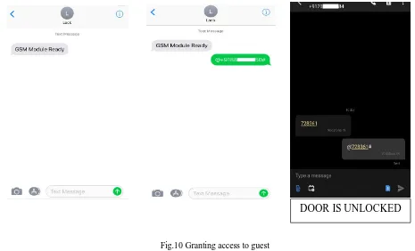
[image:6.595.57.522.449.731.2]Figure 10 shows the RMN/owner sharing access to the guest by specifying his/her number between the special characters. The door is unlocked when the guest sends the correct OTP to the lock.
Fig.10 Granting access to guest
DOOR IS
UNLOCKED
3264
©IJRASET: All Rights are Reserved
C. Intruder Alert
[image:7.595.54.535.162.406.2]Figure 11 shows a warning message sent to the RMN along with intruder’s details when an unauthorized person tries to gain access and unlock the door.
Fig.11 Intruder alert
VI.CONCLUSIONSANDFUTUREWORK
The system developed is cost effective. It has reliable network coverage because GSM is used instead of Wi-Fi whose coverage is restricted. Remote access from anywhere around the world is possible. Random 6-digit OTP is generated during each request. Access can be shared with trusted persons via OTP. Status alerts are sent to the registered mobile number each time the door is locked/unlocked. Intruder alert is sent to the RMN when an unauthorized person tries to unlock the door even with a correct OTP. Following improvements are suggested for future development of this system,
1) An optional smart phone app can be developed to simplify the manual entering of commands by RMN to unlock the door.
2) For more enhancement in security, cameras for face authentication can be integrated with the current system.
REFERENCES
[1] Adnan Ibrahim, Afhal Paravath, Aswin P. K., Shijin Mohammed Iqbal and Shaeez Usman Abdulla, "GSM Based Digital Door Lock Security System", 2015 IEEE International Conference on Power, Instrumentation, Control and Computing (PICC), 978-1-4673-8072-0.2015.
[2] Pradip Tilala, Anil K. Roy and Manik Lal Das, "Home Access Control through a Smart Digital Locking-Unlocking System", Proc. of the 2017 IEEE Region 10 Conference (TENCON), Malaysia, November 5-8, 2017
[3] Ushie James Ogri, Donatus Enang Bassey Okwong, Akaiso Etim," Design and construction of Door Locking Security System Using GSM", International Journal Of Engineering And Computer Science ISSN:2319-7242 Volume 2 Issue 7, Page No. 2235-2257, July 2013
[4] Pratiksha Misal, Madhura Karule, Dhanshree Birdawade, Anjali Deshmukh, Mrunal Pathak, "Door Locking/Unlocking System using SMS Technology with GSM/GPRS Services", International Journal of Electronics Communication and Computer Engineering Volume 5, Issue 4 July, Technovision2014, ISSN 2249071X, April 2014.
[5] Yanbo Zhao, Zhaohui Ye, "A low cost GSM/GPRS based wireless home security system", Consumer Electronics, IEEE Transactions on (Volume:54 , Issue: 2 ), May 2008.
[6] B. Yusekkaya, A. A. Kayalar, M. B. Tosun, M. K. Ozcan, and A. Z. Alkar, "A GSM, internet and speech controlled wireless interactive home automation system," IEEE Trans. Consumer Electron., vol. 52, no. 3, pp. 837-843, Aug. 2006.
[7] Piyare, R.; Tazil, M., "Bluetooth based home Automation System using Cell Phone", IEEE 15th International Symposium on Consumer Electronics, pp. 192-195, 2011.
[8] Huiping Huang, Shide Xiao, Xiangyin Meng and Ying Xiong, "A Remote Home Security System Based on Wireless Sensor Network and GSM Technology", Second International Conference on Networks Security Wireless Communications and Trusted Computing 2010, vol 1 , pp 535-538, April 2010.
[9] Ahmad A.W., Jan N., Iqbal S. and Lee C., " Implementation of ZigBee-GSM based home security monitoring and remote control system", IEEE 54th International Midwest Symposium on Circuits and Systems (MWSCAS), 2011, pp. 1-4.