High-loading Velocity Tensile Properties and Fracture Behavior
of SiCp/AC4CH Composite
*Lei Wang
1;2, Toshiro Kobayashi
1, Chunming M. Liu
2and Tomokazu Masuda
11
Department of Production Systems Engineering, Toyohashi University of Technology, Toyohashi 441-8580, Japan
2Institute of Materials Research, School of Materials and Metallurgy, Northeastern University,
Wenhua Road 3-11, Shenyang 110004, P. R. China
This study conducted a high-loading velocity tensile test for a SiCp/AC4CH composite and an AC4CH alloy (Al-6.7%Si-0.3%Mg alloy). Microstructures of both materials before and after tensile testing were carefully examined with an optical microscope and SEM. Experimental results demonstrate that the ultimate tensile strength (UTS) of the SiCp/AC4CH composite increased with increasing loading velocity up to 10 ms1. Compared to the AC4CH alloy, the fracture elongation of the SiCp/AC4CH composite is more sensitive to the strain rate. The AC4CH
alloy yield strength (YS) shows more sensitivity than that of UTS with increasing strain rate, especially in the range of loading velocity higher than 1 ms1. The composite failed by coalescence of microcracking/microvoiding. The ratio of broken SiC particles increases with increasing
loading velocity.
(Received November 5, 2003; Accepted March 15, 2004)
Keywords: high loading velocity, fracture behavior, composite, tensile test
1. Introduction
Applications of new materials to reduce the fuel con-sumption and improve thermal efficiency of engines are required in automobile industries to mitigate environmental and energy problems. Application of aluminum matrix composites is inferred to be an effective method for new engine parts because aluminum alloys reinforced with discontinuous reinforcements (e.g. particles, whiskers or short fibers) can provide desirable mechanical properties.1,2) Largely driven by these applications, extensive theoretical and experimental studies have been undertaken in recent years.3–5)On the other hand, following the increasing of high-speed machines, it is important to understand the behavior of these materials at different loading velocities. However, most studies of MMCs have limited their scope to the static loading condition. In addition to the increase in flow stress with increasing loading velocity, an increase in tensile elongation at high rate was also present, as reported in several investigations.3–5) Kobayashi et al.5) found that the crack growth until the maximum load point in dynamic loading condition is slightly faster than that in static loading condition. The present study is intended to investigate the effect of loading velocity (Vl) from5106to 10 ms1on tensile property and fracture behavior of a SiCp/AC4CH composite.
2. Experimental Procedure
The material used in the present study was AC4CH alloy matrix composite reinforced with 20.6 vol% SiC particle (SiCp), which was fabricated using the melt-stirring method. The solid solution treatment was performed at 808 K for 9 ks followed by water quenching, then heated at 443 K for 32.4 ks. For comparison, a AC4CH specimen was prepared
by the same process with the composite. The tensile specimen was machined after treatment, possessing a geometry consisting of two parallel sections.6)The diameter of the thick section was 7 mm and the thinner one, gage section, 4 mm. The length of the reduced 4 mm diameter section was machined to 24 mm with a gauge length of 20 mm. Two strain gages were applied, one on each of the two sections. The strain gage on the gage length portion (SG1) was for the strain signal measurement during testing; the strain gage on the thick section (SG2) was for measure-ment of the load applied to the specimen during testing. Quasi-static tensile tests were conducted prior to the high velocity tests using an Instron universal testing machine. The load calibration value obtained for SG2 was used to convert the SG2 output to load for the high velocity tests. A high-velocity loading test was carried out using a servo-hydraulic testing machine. Fracture surfaces of tested specimens were examined using a scanning electron microscope (SEM) to elucidate the fracture behavior under various loading velocities. Specimen surfaces (which were polished before testing) near the fracture surface were also analyzed with SEM. The tested materials’ microstructures were analyzed quantitatively using an image analysis system.
3. Results and Discussion
3.1 Influence of loading velocity on tensile properties
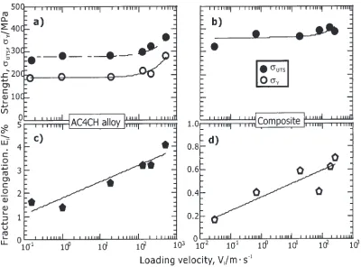
Typical load-deflection curves with various loading velo-cities of testing materials are depicted in Fig. 1. Composite curves are nearly pure elastic fracture (no evident general yield); those of AC4CH alloy are with evident general yield. Notably, the maximum load of both composite and AC4CH alloy increased with increasing loading velocity, but the degree of increase of the composite was larger than that of the AC4CH alloy. Moreover, the deflection of both materials increased at loading velocity of 10 ms1. Figure 2 shows the relationship between tensile properties and loading veloc-ities. Both tensile and yield strength of the composite and *This Paper was Presented at the Autumn Meeting of the Japan Institute of
Metals, held in Sapporo, on 12 October, 2003.
Materials Transactions, Vol. 45, No. 5 (2004) pp. 1738 to 1742
Fig. 1 Typical load-deflection curves of a) the AC4CH atVl¼8:3106ms1; b) the AC4CH atVl¼10ms1; c) the composite at Vl¼8:3106ms1; d) the composite atVl¼10ms1, respectively.
[image:2.595.97.500.71.365.2] [image:2.595.98.498.435.731.2]AC4CH alloy increased with increasing loading velocity. Generally, the influence of loading velocity on mechanical properties can be illustrated by strain rate sensitivity
m¼ ð@lnxÞ=ð@ln _""Þ. The testing results of the present
materials are calculated by that equation. We found that m
for both tensile strength and yield strength of AC4CH is
3:0102; however, for the composite material, m for tensile strength is 4:6102. Comparison with AC4CH shows that tensile strength of the composite shows higher strain sensitivity. Such results are attributable to the micro-structural difference between the composite and AC4CH alloy. Quantitative analysis by image analysis revealed the difference. Table 1 shows analysis results of adding SiCp into the composite: the aspect ratio of Si decreased from 2.08 to 1.84; the average diameter of Si decreased from 3.03 to 2.08mm; also, the circularity (Circularity:FðsÞ ¼P2=4A,P: Perimeter of particle, A: Area of particle) of Si particles increased from 1.89 to 1.78. Reportedly, grain size strongly affects7)fracture behavior under a dynamic tensile loading condition. Moreover, adding reinforcing SiC whiskers8) or particles9)increased the dislocation density of the composite. Such increase influences the strength under a dynamic
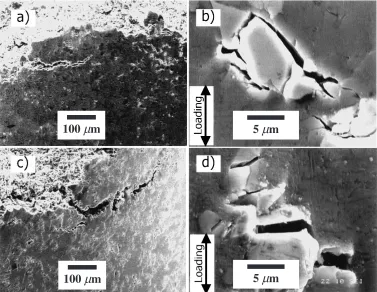
loading condition. The present composite failed through shear localization that occurred in an inhomogeneous plastic deformation process in the matrix and through void forma-tion around SiC particles. The reason will be explained later in detail. The tensile strength was more strongly influenced by changing loading velocity than that of AC4CH because the composite material microstructure is more homogeneous than that of AC4CH. In addition, the composite material can be not deformed with a larger amount of plastic deformation (failure elongation of the composite is less than 1%). Furthermore, because strain rate dependence is determined mainly by the work-hardening rate,10)it caused the composite to show higher loading-velocity sensitivity. On the other hand, from the viewpoint of incubation time of fracture,11)we inferred that strength of the composite will increase with increasing loading velocity because of the higher Young’s modulus of the composite. Moreover, Fig. 4 shows that slip bands can be observed on the composite specimen surface after tensile testing. Slip bands are much more numerous at high loading velocity (refer to Fig. 4d)) than at lower loading velocity (Fig. 4b)). The slip occurred by dislocation and the moving force of dislocation increases with dislocation moving speed,12)which may further explain the increasing tensile strength and the increasing loading velocity.
[image:3.595.46.291.95.135.2]On the other hand, as shown in Figs. 2c) and d), failure elongation of both materials increased with increasing loading velocity. As explained later in more detail, the occurrence of microcracking and microvoiding extended widely around the main fracture surface of the composite material. That phenomenon followed the increase of loading
Table 1 Comparison of Si particles characteristics in the composite and the AC4CH alloy
Aspect ratio Average diameter /mm Circularity
MMC 1.84 2.08 1.78
AC4CH 2.08 3.03 1.89
50
µ
m
50
µ
m
50
µ
m
50
µ
m
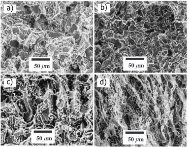
Fig. 3 SEM micrographs of the composite (a) and b)) and the AC4CH alloy (c) and d)) at loading velocity of 0.01 ms1(a) and c)) and
10 ms1(b) and d)).
[image:3.595.107.491.459.757.2]velocity. Concurrently, more SiC particles were visible on the fracture surface (refer to Fig. 3). These factors can explain increasing of fracture elongation with increasing loading velocity for the composite material. For AC4CH alloy, the increased fracture elongation was caused by different factors. The AC4CH alloy failed through void occurrence and coalescence after slip deformation. Another cause was microvoiding. Therefore, the main reasons for the increasing of fracture elongation caused by increasing loading velocity were the numerous slipping bands (refer to Fig. 5) and heat generation (refer to Fig. 1b)). Comparison of the composite and AC4CH alloy shows that their increase ratios of elongation are almost identical.
3.2 Fracture behavior
Typical SEM fractographs of a fracture surface and a specimen surface of the composite at two loading velocities are shown in Fig. 3. Comparison of Fig. 3a) (Vl¼
0:01ms1) with 3b) (V
l¼10ms1) shows that more SiC particles were broken with high loading velocity at the same time that many microcracks occurred. Moreover, Figs. 3c) (Vl¼0:01ms1) and d) (Vl¼10ms1) show that many microvoids formed near the fracture surface, especially at higher loading velocity. Such microvoids appeared over a wide region of fracture surface. Such phenomena can be observed more clearly from the cross section of the failed specimen, as shown in Fig. 4. Considered along with the mechanical properties stated above, the present composite appears to have fractured through initiation and coalescence of microcracking and microvoiding. Nevertheless, it was noted that more microcracks by SiC particle were broken at
higher loading velocity than in the lower loading velocity condition. For aluminum matrix MMC materials at high strain rate testing, it has been confirmed that stress waves accompanying impact will enlarge the void and induce plastic deformation in the matrix.13) At lower loading velocity, stress concentration and the triaxial stress state at crack tip will engender the final fracture. Moreover, as shown in Fig. 4d), more slip bands occurred following the increase of loading velocity. Such slip bands are surrounded by broken SiC particles. These may be the reason that the composite fractured with many broken SiC particles at a higher loading velocity. The same phenomenon was observed in a 2124 aluminum alloy sample reinforced with SiC whisker compo-site material at high strain rates.4) The increase of fracture elongation (deflection) at higher loading velocity is attribut-able to enlarged microvoids and numerous instances of microcracking.
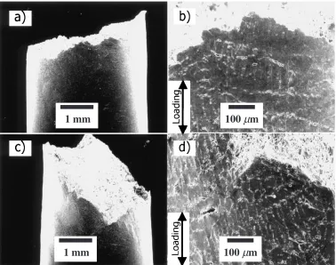
Typical SEM fractographs of the fracture and specimen surfaces of the unreinforced AC4CH are shown in Fig. 5. Microvoiding and microcracking occurred with severe slippage within a wide region of the fracture surface at high loading velocity. Comparison of Fig. 5a) (Vl¼0:01ms1) with 5b) (Vl¼10ms1) clarifies that the microvoids became larger and deeper following increased loading velocity, indicating that local slipping caused by shear deformation might occur within a wide region of the fracture surface at the same time. In addition, microvoids and microcracks initiated following such slippage. At a lower loading velocity, the microvoids coalesce at a perpendicular direction (refer to Fig. 5b)) to the loading direction. They lead to eventual fracture. However, at a higher loading velocity,
100
µ
m
100
µ
m
5
µ
m
5
µ
m
[image:4.595.109.486.73.365.2]the larger parts of microvoids might not have sufficient time to join; they must grow along the maximum shear stress direction. As shown in Fig. 5d), microvoids formed at a certain angle to the loading direction (this direction may be with the maximum shear stress). Some severely enlarged microvoids might coalesce to form a crack; such cracks grow or join to engender fracture. Moreover, some rises and falls are visible on the load-deflection curve occur after the yield point, as shown in Fig. 1b). Such phenomena have been found for 6061 aluminum alloy under high strain rate deformation.14,15) Those phenomena are caused by heat generation. Because such heat generation occurred in the present case, it led to easy microvoid growth. Therefore, the dimples became larger at higher loading velocity, even in a short time.
4. Summary
An experimental study was conducted at room temperature to investigate effects of loading velocity on tensile properties and fracture behavior of SiCp/AC4CH composite. The main results are summarized as the following.
(1) Tensile properties of SiCp/AC4CH composite at load-ing velocities from5106to 10 ms1reveal that the composite tensile strength increases remarkably with increased loading velocity. This increase is related to Si refinement and increasing dislocation density by the added SiC particles.
(2) SEM fractographs indicate that the composite failed by the occurrence and coalescence of microcracks and microvoids that accompanied increased loading veloc-ity; the ratio of broken SiC particles increases. The increased number of slip bands causes this increase with increasing loading velocity.
REFERENCES
1) R. J. Arsenault, S. Fishmen and M. Taya: Progress Mater. Sci. 38
(1994) 1–157.
2) D. J. Lloyd: Inter. Mater. Rev.39(1994) 1–23.
3) D. L. McDaniels: Metall. Trans. A16A(1985) 1105–1115. 4) S. M. Pickardet al.: Scr. Metall.22(1988) 601–606.
5) T. Kobayashi, M. Murakami and H. Toda:Proc. Mech. Mech. of Comp. Frac., (ASM, 1993) pp. 41–46.
6) Z. M. Sunet al.: Metall. Mater. Trans. A29A(1998) 263–269. 7) T. Mukai, T. Aizawa and K. Higashi:Found. Issues & App.
Shock-Wave and High-strain-rate phenomena, ed. by K. P. Staudhammer, L. E. Mutt and M. A. Meyers (Elsevier Science Ltd., Orlando, 2001) pp. 37–42.
8) L. Wanget al.: Mater. Sci. Eng.A280/1(1999) 214–219. 9) L. H. Qianet al.: Mater. Sci. Eng.A318(2001) 189–196. 10) D. Dulyet al.: Acta Mater.44(1996) 2947–2962. 11) J. F. Kalthoff: Eng. Fracture Mech.23(1986) 311–319. 12) H. W. Schadler: Acta Metall.12(1964) 861–870.
13) C. C. Peng, J. R. Hwang and J. L. Doong: Mater. Sci. Eng.A171(1993) 213–218.
14) T. Masudaet al.: Mater. Sci. Forum426–432(2003) 285–290. 15) L. Wang:Postdoctoral Thesis, (Northeastern Univ., July 2003) pp. 91–
111.
100
µ
m
1 mm
100
µ
m
1 mm
Fig. 5 Cross section of SEM micrographs of the AC4H at loading velocity of 0.01 ms1(a) and b)) and 10 ms1(c) and d)).
[image:5.595.109.487.72.370.2]