Some Characteristics of AZ31/AZ91 Dissimilar Magnesium Alloy Deposit
by Friction Surfacing
Dai Nakama
*, Kazuyoshi Katoh and Hiroshi Tokisue
College of Industrial Technology, Nihon University, Narashino 275-8575, Japan
Monolayer friction surfacing was performed using a numerical controlled full automatic friction welding machine for AZ31 magnesium alloy plate used for substrate and AZ91 magnesium alloy casting bar used for consumable rod. Effect of the surfacing conditions on structures and mechanical properties of deposit were investigated. It was clearly observed that the circular pattern appeared on the surface of deposit by the rotation of coating rod. Microstructures of deposit showed finer structure than that of both base metals, and the cast structure was disappeared. Hardness of the deposit showed higher value than that of the substrate. Wear resistance of the deposit was improved in comparison with the substrate. [doi:10.2320/matertrans.MC200779]
(Received October 5, 2007; Accepted January 28, 2008; Published March 12, 2008)
Keywords: friction surfacing, magnesium alloy, microstructures, hardness, wear test
1. Introduction
Friction surfacing is proposed as one of the surface modification methods to produce thick layer on the substrate. It is a solid state process with a frictional heat that bonds the coating to the substrate without problems such as porosities or slag inclusions.1)And the function by surfacing dissimilar materials to the material surface to be modified takes place in solid state. Therefore, minimal thermal effects on base materials can be anticipated. The authors studied the effect of surfacing conditions on both the shape of deposit and mechanical properties of friction surfaced material combined by aluminum alloy plate and bar.2,3)As a result, the thickness
of deposit was controlled if the appropriate surfacing conditions were chosen, and it was clarified that good deposit was obtained. The similar friction surfaced material using 5052 aluminum alloy plate and bar was possible to form a deposit with the fine structure on the substrate. However, softening area has been observed in the vicinity of deposit on the substrate.
It is significant to do surface modification by friction surfacing using a hard material without damaging a charac-teristic of matrix.
The authors studied the friction surfacing that is combined by 5052 aluminum alloy plate and 2017 aluminum alloy bar. As the results, it was clarified that hard surface deposit was obtained.3)
In the other, magnesium alloys increase their consumption with the purpose of light weighting, hence a study on the friction surfacing of magnesium alloy is necessary, however there are few studies on them.4)In addition, it is predicted that
friction surfacing is difficult as for the magnesium alloy which the movement of faying surface to the axial direction to be seen in stud friction welding is hard to produce.5)
In this study, dissimilar friction surfacing was conducted with AZ31 magnesium alloy plate as a substrate and cast AZ91 magnesium alloy bar as a coating material. Effect of rotational speed of rod on the structures and mechanical properties of friction surfaced material has been studied.
2. Experimental Procedure
AZ31 magnesium alloy plate of 6 mm thickness as a substrate was machined to 50 mm width and 150 mm length. AZ91 magnesium alloy casting bar of 18 mm diameter and 100 mm length was used as a consumable rod. Chemical compositions and mechanical properties of both base metals are summarized in Table 1 and 2, respectively.
[image:1.595.304.549.310.354.2]Friction surfacing was performed using a numerical controlled fully automatic friction welding machine. The friction surfacing was conducted by the restriction length of consumable rod (i.e., the surfacing was terminated when 30 mm of consumable rod was consumed or a maximum feed length of 90 mm in relation to the substrate.) was attained. By referring to the results of preliminary experiments,2,4) the friction surfacing was performed under the surfacing conditions shown in Table 3.
Table 1 Chemical composition of base metals. (%)
Materials Al Zn Mn Si Cu Fe Ca Ni Mg
AZ91 8.83 0.62 0.20 0.01 0.002 — — Tr. Bal.
[image:1.595.303.550.397.450.2]AZ31 3.5 1.3 1.0 0.05 0.05 0.005 0.04 0.005 Bal.
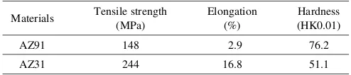
Table 2 Mechanical properties of base metals.
Materials Tensile strength (MPa)
Elongation (%)
Hardness (HK0.01)
AZ91 148 2.9 76.2
AZ31 244 16.8 51.1
Table 3 Friction surfacing conditions.
Rotation speed N (min1) 1000, 1250, 1500
Friction pressure P (MPa) 40
Traverse speed f (mm/s) 5
Preheating time t (s) 5
*Graduate Student, Nihon University
[image:1.595.303.548.491.550.2]Observation of the appearances, macro- and microstruc-tures, hardness tests and wear test using an Ohgoshi-style wear tester were conducted at room temperature. The counter material for the wear test with 30 mm in diameter and 3 mm in thickness was made of spheroidal graphite cast iron. The wear test conditions are shown in Table 4. Temperature during friction surfacing was measured with thermocouples. The measurement positions are shown in Fig. 1.
3. Results and Discussions
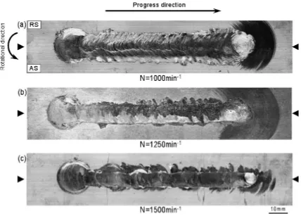
3.1 Observations of appearance and shape of deposits
The appearance of deposit is shown in Fig. 2. A circular pattern due to the rotation of consumable rod was observed on the surface of deposit regardless of rotational speed. The circular patterns are similar to those appeared on the surface of aluminum alloy deposits.2,3)The deposit has a tendency to
incline toward the same direction as the rotational direction of the consumable rod and the surfacing direction (advancing side: AS, and in the surfacing direction opposite to them which is called retreating side: RS). This may be due to the dynamic relationship between direction of rotation and traveling direction of consumable rod. The force on the advancing side of the surfaced area in this experiment will be generated in the direction of rotation, which the consumable rod is shifted forward. On the retreating side, the force will be generated in the direction in which the consumable rod is shifted backward. Therefore, the consumable rod was shifted on the advancing side. A similar tendency was report for the case of substrate and bar made of a 5052 aluminum alloy plate and 2017 aluminum alloy respectively.3)
[image:2.595.46.288.210.254.2]The effect of rotation speed of consumable rod on the thickness, width, and length of deposit are shown in Fig. 3. The thickness of deposit decreased with increasing rotation speed of consumable rod. The width of deposit tended to decrease with an increase of the rotation speed. This might be attributed to that width of the deposit is decreased by a decrease in the closure area of substrate and consumable rod. For the identical reason for the decrease in the closure area seen during friction with increasing rotational speed of Table 4 Wear test conditions.
Friction load P0 (N) 20.6, 31.4, 61.8
Friction speed V (m/s) 1.97
Friction distance L0 (m) 200
Fig. 1 Measurement positions of temperature.
[image:2.595.52.284.288.426.2] [image:2.595.85.513.462.769.2]consumable rod which is exhibited during friction welding.6)
The ideal length of the deposit is 108 mm that is calculated from the feed distance and the diameter of the consumable rod. The effect of the rotational speed on the length of deposit was small, and the length reached almost 108 mm under all conditions. These tendencies are similar to those observed in aluminum alloy deposit, however the thickness of deposit
was thinner and the width of deposit was narrower in comparison with the aluminum alloy deposit.
The surfacing efficiency was determined based on the assumption that the weight ratio of the consumable rod before and after surfacing is associated with the shape of deposit. The results of measurements of surfacing efficiency are shown in Fig. 4. The surfacing efficiency was lowered with increasing rotational speed of the consumable rod. This tendency is similar to that observed in the friction surfacing using an aluminum alloy. The surfacing efficiency is remarkably small as 20%–60% of that of the aluminum alloy deposit.
It is considered that the difference of the surfacing efficiency of both materials was due to a difference of the ductility that affected the movement of the faying surface.
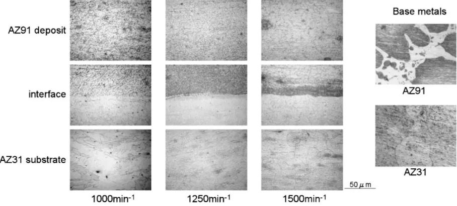
3.2 Microstructures of deposits
Microstructures of base metals and deposit are shown in Fig. 5. The deposit showed finer structure than those of both
80 90 100 110 120
Length,
Ld
/mm
5 10 15 20
Width,
Wd
/mm
800 1000 1200 1400 1600
0 0.2 0.4 0.6
Thickness,
Td
/mm
Rotational speed,
N
/min
-1Fig. 3 Size of deposit.
800 1000 1200 1400 1600
0 5 10 15 20
Rotational speed,
N
/min
-1Surfacing efficiency (%)
Fig. 4 Result of surfacing efficiency.
[image:3.595.55.286.71.417.2] [image:3.595.315.542.75.272.2] [image:3.595.71.525.565.770.2]base metals, in addition cast solidified structure observed in the base metal of rod was not observed in the deposit.
The weld interface can be clearly distinguished between the deposit and the substrate. Although observations of weld penetration of coating material into a substrate have been reported in surfacing by fusion welding.7)However, on the
present friction surfacing, which is a solid-state surface modification technology, penetration of the coating material into the substrate was not observed. In addition, no mechanically mixed layer as represented for the case of aluminum alloy3)was observed at the weld interface between the deposit and the substrate.
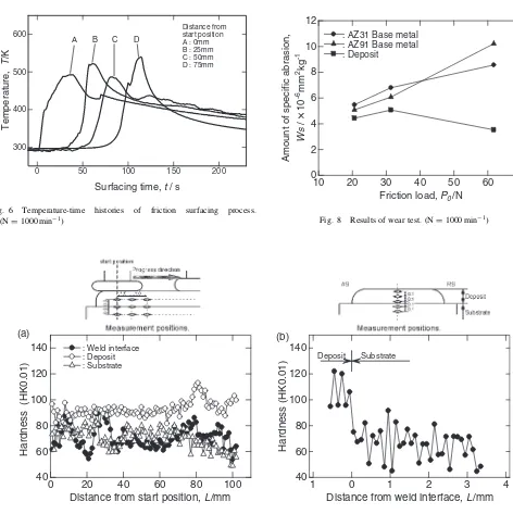
3.3 Temperature histories
Figure 6 shows temperature-time curves during friction surfacing at the measurement points shown in Fig. 1. The temperature of each measurement point rose with an approach of the coating rod and reached at the highest
temperature right after the coating rod has passed by. This tendency was similar to friction surfaced aluminum alloy using a 5052 aluminum alloy plate and bar.2)And the highest
temperature of each measurement point became higher with it leaving from a starting point, and the highest temperature of 538 K was observed at 75 mm from the starting point. This was probably due to temperature-rise which becomes big by heat conduction with leaving the start point.
The maximum temperature of surfacing process was lower than that in the case of friction surfacing by aluminum alloy.2,3) This is because melting point of AZ31 and AZ91 magnesium alloy were lower than those of 5052 and 2017 aluminum alloys.
3.4 Hardness and wear tests
Hardness distributions of deposit were shown in Fig. 7. In Fig. 7(a), hardness values have the unevenness like a base metals in both places, but no clear change was observed for
0 50 100 150 200
300 400 500 600
Surfacing time, t / s
Temperature,
T
/K
Distance from start position A : 0mm B : 25mm C : 50mm D : 75mm
A B C D
Fig. 6 Temperature-time histories of friction surfacing process. (N¼1000min1)
0 20 40 60 80 100
40 60 80 100 120 140
Hardness (HK0.01)
Distance from start position, L/mm
: Weld interface : Deposit : Substrate
(a)
0 1
40 60 80 100 120 140
Distance from weld interface, L/mm
Hardness (HK0.01)
Deposit Substrate
1 (b)
2 3 4
Fig. 7 Hardness distributions ob deposit. (N¼1000min1)
10 20 30 40 50 60 70
0 2 4 6 8 10 12
Amount of specific abrasion,
Friction load, P0 /N
: AZ31 Base metal : AZ91 Base metal : Deposit
-6mm 2kg
-1
Ws
/
×
10
[image:4.595.55.527.304.777.2] [image:4.595.315.539.318.489.2]the hardness distribution. In Fig. 7(b), the hardness of deposit was higher than that of the substrate. Hardness change such as softened area like an aluminum alloy deposit on substrate could not be recognized. Hardness of the deposit showed higher value than that of the AZ91 magnesium alloy base metal. The hardness distribution is similar to that of AZ31 magnesium alloy friction welded to AZ91 magnesium alloy castings.5) Difference in hardness of the deposits was considered to be cast structure of the AZ91 magnesium alloy base metal which is consumable rod became the fine structure by friction surfacing.
Results of wear tests are shown in Fig. 8. Specific wear of both base metals tended to increase with increasing friction load, and little difference of specific wear values between the materials was obtained. Specific wear of the deposit showed lower value than those of both base metals. It was clear that friction surfacing improved the wear resistance. It is considered that the deposit became to have fine structure and hence of hardness.
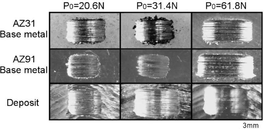
Surfaces of wear tested specimen were shown in Fig. 9. In case of a friction load of 6.3 kg, width of wear mark on both base metals were large, while the deposit showed smaller width and this value was the same as that of base metals at a low friction load.
4. Conclusions
Friction surfacing was conduced using AZ31 magnesium alloy plate as a substrate and AZ91 magnesium alloy bar
using a coating rod. The influence of surfacing conditions on structure and mechanical properties of the friction surfaced material has been investigated. The following results were obtained.
1) The circular pattern due to the rotation of consumable rod was clearly observed on the surface of deposit. 2) The cast structure which was observed in AZ91 alloy
base metal was not observed in the deposit. Micro-structure of the deposit was finer than that of the consumable rod and substrate.
3) The highest temperature during surfacing process was 538 K at 75 mm position from the starting point. 4) Hardness of the deposit was higher than that of the
AZ91 magnesium alloy base metal.
5) The deposit showed higher wear resistance than those of both base metals.
REFERENCES
1) E. D. Nicholas and W. M. Thomas: Weld. J.65(1986) 17–27. 2) H. Sakihama, H. Tokisue and K. Katoh: Mater. Trans.44(2003) 2688–
2694.
3) H. Tokisue, K. Katoh, T. Asahina and T. Ushiyama: Mater. Trans.47
(2006) 874–882.
4) H. Sakihama, H. Tokisue and K. Katoh: Proc. of The 100th Conf. Jpn. Inst. Light Met. (2001) 223–224.
5) K. Katoh, T. Asahina and H. Tokisue: J. Jpn. Inst. Light Met.44(1994) 562–566.
[image:5.595.85.512.70.278.2]