Graphitization Potential of Cast Iron Powder
in Atmospheric Plasma Spray Conditions
I. Ozdemir
1;2, Y. Tsunekawa
1;*, M. Okumiya
1and T. Ueno
1 1Toyota Technological Institute, Department of Advanced Science and Technology, Nagoya 468-8511, Japan
2Dokuz Eylul University, Department of Metallurgical and Materials Engineering, Bornova, Izmir, 35100, Turkey
Graphitization behavior of water-atomized cast iron powder at each thermal spraying step, such as droplet flight, droplet impingement and splat layering, was successively examined. Both as-atomized cast iron powder and coatings sprayed with the powder contain no graphite structure owing to their rapid solidification. A short period of pre-annealing at 1173 K allows the formation of graphite structure in the cast iron powder, in which there exist precipitated graphite of 3.58 mass%. The microstructure observation exhibits that pre-existed pores in the as-atomized powder strongly affect the precipitating sites of graphite, that is, mainly inside the individual powder instead of the surface. However, marked reduction in graphite structure occurs to coatings sprayed with the pre-annealed powder because of in-flight burning and dissolution into molten iron. In-process post-annealing at 773 K for 60 s reveals the formation of graphite structure resulted from the decomposition of iron based metastable carbide in splats and coatings sprayed with the as-atomized powder. Chemical analysis demonstrates that graphitization level of post-annealed cast iron coatings is higher than that of coatings sprayed with the pre-post-annealed powder. Precipitated intersplat graphite structure of 1.68 mass% appears in cast iron coatings when introducing methane as a powder feeding carrier gas which is liable to decompose in plasma flame. The resultant coatings with graphite structure embedded in hard matrix are anticipated to offer superior wear resistance in comparison to centrifugally cast iron containing flaky graphite of 1.76 mass%. [doi:10.2320/matertrans.47.1710]
(Received December 28, 2005; Accepted June 1, 2006; Published July 15, 2006)
Keywords: graphite, cast iron, plasma spraying, pre-annealing, post-annealing
1. Introduction
In conventional cast iron materials, graphite structure provides a renewable solid lubricating effect between mating surfaces, and flaky cavities of graphite subsequently act as an oil reservoir during running-in period under oil lubricated sliding conditions. Solid lubricants restrain the local milling action of abrasive material, and reduce the propensity for material flow at the surface.1)Thermal spraying of surface
modification process is characterized by the capability of thick coating formation with relatively short cycle time. Accordingly thermal sprayings with many kinds of ferrous powders have been applied to a wide range of industrial applications especially in automotive industries.2,3) Taking
the self-lubricating effect of graphite into consideration, it is expected the possible reduction in friction coefficient and wear loss. Thermally sprayed cast iron coatings containing graphite structure are anticipated to improve the wear resistance of aluminum alloys which have poor tribological properties.4–6) Coatings sprayed with water-atomized cast iron powder which is less expensive than gas-atomized powder, exhibit superior wear resistance arising from graph-ite structure embedded in hard matrix.7) However, the
precipitation of graphitized carbon distributed throughout ferrous coatings is not a quite simple process due to the rapid solidification of flattened splats.8,9)Pre-annealing of powders,
post-annealing of coatings and in-process graphitization are three major promising approaches to achieve graphite structure in cast iron coatings without introducing additional solid lubricant. Although the last method is the most favorable, as yet, no accomplished attempts have been reported on this approach. In the case of spraying cast iron powders with highly concentrated alloying elements of
aluminum and silicon which are known as a strong graphitizer and anti-oxidizer, significant reduction in oxide levels has been obtained in comparison to the sprayed bearing steel coatings,10)whereas graphite loss from burning during the droplet flight has occurred after plasma spraying in air atmosphere.11) Moreover, when selecting improper spray
parameters, sprayed cast iron coatings may contain carbides instead of graphite. Therefore, great care should be taken to ensure that graphite formation has been promoted in cast iron coatings, which are strongly linked to the spray conditions such as preheat substrate temperature,12) spray distance,
chamber pressure13)and particle size.14)
In the present study, a series of atmospheric plasma sprayings were carried out to promote graphite structure in cast iron coatings such as spraying with pre-annealed cast iron powder, post-annealing of coatings and in-process graphitization of decomposed carbon from methane which is introduced as a powder feeding carrier gas. In order to reveal the most appreciable way for the graphitization in the atmospheric plasma spraying of cast iron powder, micro-structure observations of graphitized carbon and layered oxide were carried out along with graphitized carbon analyses at each spraying step, such as droplet flight, droplet impingement and splat layering.
2. Experimental Procedures
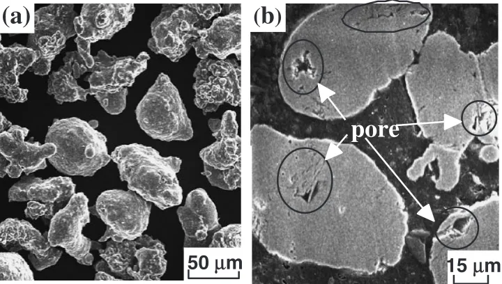
Chemical composition of the water-atomized powder for the deposition of plasma sprayed coatings is presented in Table 1, in which the oxygen content is much higher than that of ordinary gas-atomized powders. The morphology of water-atomized powder, which is irregular in comparison to spherical gas-atomized powders, is shown in Fig. 1(a). It is evident from Fig. 1(b) that some pores which affect the precipitation behavior of graphite as will be discussed later
*Corresponding author; E-mail: [email protected]
are present in the cross-section structure. The as-atomized powder is mainly consisted of Fe-C-Si, -FeCSi and AlFe3C0:5 which are identified by X-ray diffractometry
(XRD) with Co-Kradiation. The powder was then sieved into particle sizes (dp) of 32–45mmand fed into the plasma
flame as a spray material. The standard spray parameters for splat collection and coating deposition are given in Table 2. The cast iron powder was sprayed onto an aluminum alloy substrate (Al-11.2Si-2.74Cu; in mass%) kept at room temperature and constant spray distance of 100 mm. Prior to spraying, substrate surfaces were roughened through grit blasting, followed by ultrasonic cleaning in acetone. Cast iron splats were collected on a mirror finished aluminum alloy substrate without preheating. Substrate temperature was continuously recorded through a thermocouple inserted into the substrate center to prevent it from melting during the spraying.
The constituent phases and graphite structure in the as-atomized powder, splats, coatings and also sprayed particles were identified, in addition, the amount of graphitized carbon (GC) and total carbon (TC) were respectively determined by means of chemical analyses. The cross-sections of particles, splats and coatings were observed by an optical and scanning electron microscopy (SEM), and element distribution was studied by an electron probe microanalyzer (EPMA).
3. Results and Discussion
3.1 Characterization of as-atomized powder and result-ed coatings
XRD analyses reveal that the as-atomized cast iron powder is composed of rapidly solidified compounds of Fe-C-Si,
-FeCSi and AlFe3C0:5, but no graphite structure is detected
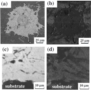
even in the particle cross-sections analyzed by EPMA. Since the solidification rate of powder during water-atomization process is much higher than that of a typical solidification rate in castings, that is why no graphite structure is available in the as-atomized powder. Likewise, typical cast iron splats and coatings sprayed with the as-atomized powder point out no graphite structure appearance as shown in Fig. 2, notwith-standing flying droplets have high temperature of their molten state. It is known that cementite structure in Fe-C system becomes a molten state over 1525 K, and also the solubility limit of graphite is approximately 6.8 mass% at a typical flying droplet temperature of 2273 K.15)Even if the powder
contains graphite before melting, graphite structure dimin-ishes to molten iron at the equilibrium state, because the powder contains 3.94 mass% of carbon or 5.13 mass% of carbon equivalent. In the case of spraying with cast iron powder, molten droplets solidify as a flattened splat at the solidification rate of107K/s which is much higher than that
in the case of conventional solidification of sand-moulded cast iron parts, that is, the extremely fast solidification rate prohibits carbon from graphitization during the solidification and cooling. Numerical simulations were carried out to predict the possibility of graphitization during the flattening and solidification of droplets. According to the splat accu-mulation model which is based on a finite difference method, the details and assumptions were given in elsewhere,7)
pore
15
µ
m
50
µ
m
(
b
)
(a)
[image:2.595.118.478.75.279.2]Fig. 1 SEM micrographs showing (a) an appearance of water-atomized powder and (b) pores in powder cross-sections.
Table 2 Standard spray parameters for cast iron coatings.
arc voltage (V) 50
arc current (A) 500
primary gas (m3/s) Ar:7:9104
secondary gas (m3/s) H
2:2:4106
carrier gas (m3/s) Ar/CH
4:1:2104
spray distance (mm) 100
particle size (mm) 32<dp<45
ambient pressure (kPa) 100 Table 1 Chemical composition of water-atomized cast iron powder
(mass%).
C Si Al O Mn Cr Ni Fe
[image:2.595.305.549.339.440.2] [image:2.595.46.291.351.379.2]spcspð@Tsp=@tÞ ¼kspð@2Tsp=@x2Þ ð1Þ
Where sp is splat density,csp splat specific heat, ksp splat
thermal conductivity. There is almost no possibility to precipitate graphite structure during the splat layering step also.
The aluminum oxide layers recognized at splat boundaries as a result of in-process oxidation are also observed in coating cross-section as shown in Fig. 3. However, the in-process oxidation level is much lower than that of sprayed bearing steel coatings.10) In other words, the in-process
oxidation can be greatly suppressed in cast iron coatings by utilizing anti-oxidized elements of silicon and aluminum
along with by shortening spray distance and installing a gas shroud system.
3.2 Characterization of pannealed powder and re-sulted coatings
It has been observed that coatings sprayed with the as-atomized cast iron powder contain no graphite structure, however, highly alloyed silicon and aluminum known as a potential graphitizer remain impotent for stimulating graphi-tization during plasma spray process. Therefore, pre-anneal-ing of the powder at 1173 K for 3.6 ks in low pressure of 10 Pa is adopted to achieve cast iron coatings containing graphite structure. The results of XRD patterns exhibit that
25
µµ
m
(a)
(b)
25
µ
m
10
µ
m
(c)
substrate
(d)
10
µ
m
substrate
Fig. 2 (a) BSE and (b) C-Kimage of splat surface, (c) BSE and (d) C-Kimage in coating cross-section sprayed with as-atomized cast iron powder.
10
µµ
m
(a)
(b)
substrate
substrate
10
µ
m
[image:3.595.152.443.74.363.2] [image:3.595.121.476.412.588.2]the pre-annealed powder is mainly composed of -Fe, Al0:7Fe3Si0:3 and graphite, in which graphitized carbon
(GC) is 3.58 mass% in total carbon (TC) of 3.89 mass%. It should be noted that porosity level is found to be approx-imately 9 vol% in the water-atomized cast iron powder, which strongly affects the precipitating sites of graphite in the annealed powder. After the pre-annealing of powder, the presence of graphite structure tends to be located inside the particle surrounding at pores as shown in Fig. 4. When considering the precipitation of graphite in the iron-based matrix, the difference in density of iron and graphite is sufficient to cause the deformation in the matrix which requires more energy to accommodate the newly formed graphite inside the iron matrix. Therefore, the graphite structure preferentially formed along the large sized pores inside the particles. The as-atomized powder contains TC of 3.94 mass% in average without GC existence. After the pre-annealing at 1173 K, the powder reaches the full graphitiza-tion level which is approximately 3.6 mass% regardless of powder size. TC slightly decreases from 3.94 mass% to 3.89 mass% in the pre-annealed powder. The variation in both GC and TC values at different graphitization steps is summarized in Fig. 5. The results imply that after annealing of the powder at 1173 K, GC level indicates a sharp increase while TC showed slightly a decrease. The ratios of GC to TC are more than 0.9 in the pre-annealed powder.
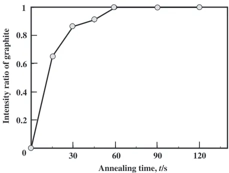
Prior to spraying the pre-annealed powder, graphitization behaviour of the water-atomized cast iron powder was also studied. The relationship between pre-annealing period at 1173 K and graphitization ratio of the water-atomized cast iron powder is demonstrated in Fig. 6. In order to determine the graphitization rate of the powder which is based on the diffracted intensity ratio of graphite, period of annealing time varied up to 120 s at 1173 K in low pressure of 10 Pa. It is concluded that the cast iron powder exhibits rapid graphiti-zation with increasing annealing time and reach full graphitization level after annealing for 60 s. In other words, the chemical composition of cast iron powder used in the present work may lead to graphitization to some extent if the spray conditions are optimized appropriately.
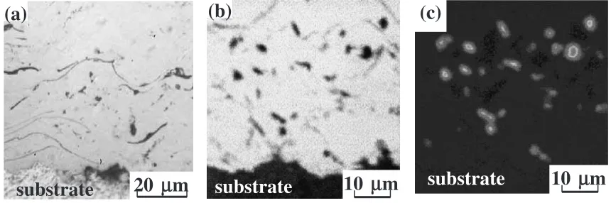
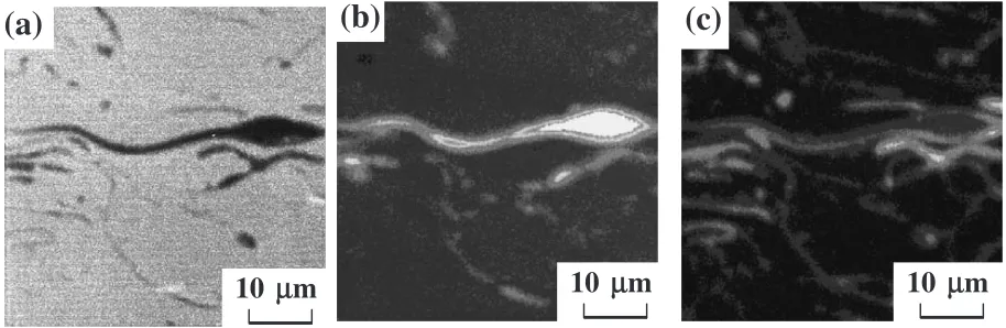
Typical cross-section microstructure of the coating, which was deposited by atmospheric plasma spraying with the pre-annealed powder, is shown in Fig. 7(a) of an optical micrograph. Dark wavy lines and chunky regions are ex-pected not only oxide layers, but also graphite structure. It is evident from C-Kimage that cast iron coating sprayed with the pre-annealed powder reveals the presence of blocky graphite structure which is also approved by an XRD pattern for the coating. However, it is of interest to note that spraying with the pre-annealed powder in atmospheric condition results in considerable reduction in both carbon contents. A
20
µµ
m
(a)
(b)
(c)
20
µ
m
20
µ
m
Fig. 4 (a) BSE, (b) C-Kand (c) O-Kimage in particle cross-section after pre-annealing at 1173 K for 3.6 ks.
0 1 2 3 4
Carbon content,
C
(mass%)
as-atomized
powder annealedpowder sprayedcoating post-annealedcoating total carbon
graphitized carbon
Fig. 5 Change in total carbon and graphitized carbon at different graphitization steps.
0 0.2 0.4 0.6 0.8 1
30 60 90 120
Intensity ratio of graphite
Annealing time, t/s
[image:4.595.73.531.72.220.2] [image:4.595.312.541.260.433.2] [image:4.595.54.285.262.418.2]significant decrease in GC can be rationalized in terms of in-flight burning and/or rapid solidification after the dissolution of GC to molten iron. A decrease in TC can be attributed to the in-flight burning of carbon which is caused by oxygen captured in the plasma flame during droplet flight and splat layering. Chemical analyses shown in Fig. 5 confirm that a marked decrease in GC is inevitable when spraying the pre-annealed powder in atmospheric plasma spray conditions.
High velocity oxyfuel (HVOF) spraying, which is charac-terized by high flame velocity and low flame temperature compared with those in plasma spraying, brings rather high GC of 2.24 mass% and TC of 3.72 mass% when spraying the pre-annealed powder. It means that low droplet temperature causes less reduction in GC due to in-flight burning and/or rapid solidification after the dissolution of graphite to molten iron.
3.3 In-process post annealing and graphitization behav-iour
As it was reported above, even though a short period of annealing is valuable for the graphitization of cast iron powders, the fact established quantitatively by carbon analy-ses that GC remarkably decreaanaly-ses from the value of 3.58 mass% in the pre-annealed powder to approximately 0.6 mass%. For this reason, in-process post-annealing process was performed to increase GC inside the coating. After spraying the as-atomized powder onto a substrate without preheating, the coating layers continuously heated up by means of plasma flame more than 60 s and the substrate temperature was kept constant at around 773 K. A typical temperature profile of the substrate during plasma spraying and post-spraying process is illustrated in Fig. 8. With the application of in-process post-annealing, the graphitization may be promoted by heating and reducing cooling rate which facilitates solid state graphitization by means of strong graphitizers such as aluminum and silicon. Besides, the decomposition of Fe-C-Si based complex carbides result in potential nucleation sites for the graphite precipitation during the extended period of high temperature. All these factors, with the possible stimulation in graphitization, increase the amount of GC in coatings. As a matter of fact that in-process post-annealed coatings contain higher amount of GC in comparison to the coatings sprayed with the pre-annealed
powder. This is because the pre-annealed powder is more prone to in-flight burning due to the high droplet temperature which considerably diminishes graphite structure. With in-process post-annealing, the content of GC is found to be approximately 1.8 mass% while TC showed a slight decrease to 3.0 mass%, which is attributed to the oxidation during splat accumulation. Consequently, the graphite structure appears in the post-annealed coatings (Fig. 9) as well as individual splat collected at a mirror finished substrate as shown in Fig. 10. In-process post-annealed coating is composed of -Fe, Al0:7Fe3Si0:3and graphite in addition to small amount of
AlFe3C0:5 and-FeCSi carbides identified by XRD. Thus, a
short period of post-annealing during spray process is sufficient to decompose significant amount of complex carbides and enables to segregate free carbon (graphite) in coating which level is much higher than spraying the pre-annealed cast iron powder as previously indicated in Fig. 5.
3.4 Graphitization behaviour with methane gas injec-tion
In order to increase the quantity of the graphite which is indispensable to reduce friction coefficient and improve wear resistance of the deposited layers methane (CH4) introduced
into a plasma flame as a carrier gas which is decomposed in high temperature plasma jet as given in below:
CH4!Cþ2H2 ð2Þ
20
µµ
m
substrate
(a)
10
µ
m
(b)
10
µ
m
(c)
substrate
substrate
Fig. 7 Cross-section microstructure of coating sprayed with pre-annealed cast iron powder, (a) optical micrograph, (b) BSE and (c) C-K
image.
Spray time, t/s 800
30 90 140 220
post-spray annealing
onset of spraying 700
600
500
400
300
Substrate temperature,
T
s
/K
0
[image:5.595.82.512.74.217.2] [image:5.595.312.542.266.416.2]Because of the high plasma jet temperature, the endothermic reaction for the decomposition of CH4 proceeds completely
to form free carbon during splat layering. Therefore, graphitization attempt is also carried out by introducing CH4 into plasma jet as a carrier gas to precipitate graphite
structure. The cross-section microstructure of sprayed coat-ing revealed the formation of thin film-like intersplat graphite structure which is approved by EPMA as shown in Fig. 11, XRD patterns as well. However, the existence of graphite between intersplats means that the approach introducing CH4
to plasma jet is not suitable to precipitate higher amount of graphite in comparison to either the spraying the pre-annealed cast iron powder or the post-annealing process. With regard to the graphite content, size and distribution in the sprayed coating, Harrieret al.16)who studied the friction behaviour of the plasma sprayed stainless steel coatings doped with graphite particles reported that the coatings containing at least 2 vol% graphite particles offers superior friction behaviour than the others containing no graphite. The resultant coatings with graphite structure embedded in hard
25
µµ
m
substrate
(a)
(b)
(c)
substrate
25
µ
m
substrate
25
µ
m
Fig. 9 Cross-section microstructure of coating graphitized by post-spray annealing, (a) BSE, (b) C-Kand (c) O-Kimage.
50
µµ
m
(a)
(b)
(c)
[image:6.595.72.530.73.224.2]50
µ
m
50
µ
m
Fig. 10 Sprayed and post-annealed splat with as-atomized cast iron powder, (a) BSE, (b) C-Kand (c) O-Kimage.
10
µµ
m
(a)
(b)
10
µ
m
10
µ
m
(c)
[image:6.595.70.530.273.422.2] [image:6.595.69.526.476.625.2]matrix in the present study are anticipated to offer superior wear resistance in comparison to centrifugally cast iron containing flaky graphite of 1.76 mass%.11)
4. Conclusions
The graphitization behaviour of water-atomized cast iron powder deposited on an aluminum alloy substrate by atmospheric DC plasma spraying was studied. Pre-annealing of the spray material, in-process post-annealing of coatings and injection of CH4to plasma jet were applied to graphitize
the cast iron powder and coatings. After the evaluation of experimental observations the following are concluded:
(1) The graphite structure in plasma sprayed coatings with the as-atomized powder is not recognized even though alloying elements in high percentages, such as alumi-num and silicon which are a strong graphitizer in cast iron.
(2) Pre-annealing of powder allows the precipitation of graphite structure in the cast iron powder with GC of 3.58 mass%. The cast iron powder exhibits rapid graphitization in a short time period of pre-annealing and reach full graphitization level less than 120 s at 1173 K. However, a significant reduction in GC, over 70%, occurs mainly due to the in-process droplet oxidation and the graphite dissolution to molten iron. (3) A short period of in-process post-annealing, such as at
773 K for 60 s, is valuable for the graphitization which content is approximately 1.8 mass%.
(4) Based on the decomposition of CH4which is introduced
as a carrier gas in high plasma jet temperature, thin film-like intersplat graphite structure appears in the cast iron coatings.
Acknowledgement
The present work partially was supported by the Grants
in Aid for Scientific Research (No. 17360360) from the Japanese Ministry of Education, Culture, Sports, Science and Technology.
REFERENCES
1) R. Elliot:Cast Iron Technology, (Butterworth & Co. Ltd, 1998) pp. 32– 33.
2) G. Barbezat: International J. Automot. Technol.2(2001) 47–52. 3) K. Funatani, M. Yoshida and Y. Tsunekawa: Alloy production and
materials manufacturing; Surface modification, ed. by G. E. Totten,
D. S. MacKenzie, (Mercel Dekker Inc. 2003) pp. 536–537.
4) S. Uozato, K. Nakata and M. Ushio: Surf. and Coat. Technol.169–170
(2003) 691–694.
5) A. Edrisy, T. Perry, Y. T. Cheng and A. T. Alpas: Wear251(2001) 1023–1033.
6) B. Hwang, J. Ahn and S. Lee: Metall. Mater. Trans. A33(2002) 2933– 2945.
7) Y. Tsunekawa, I. Ozdemir, T. Ueno and M. Okumiya: Conference on Surface Modification Technologies, SMT 18, ed. By T. S. Sudarshan, Dijon, France, (ASM International, Materials Park, Ohio, 2005) in press.
8) H. Horie, S. Hiratsuka, T. Kowata, X. Shi, K. Koike and H. Endo: J. JFS
73(2004) 662–667.
9) K. Murakami, N. Fujita, Y. Hanatate, S. Adachi and H. Nakajima: J. High Temp. Soc.27(2001) 250–255.
10) Y. Tsunekawa, T. Ueno, M. Okumiya and T. Yashiro: Surf. Eng.19
(2003) 17–22.
11) I. Ozdemir, T. Ueno, Y. Tsunekawa and M. Okumiya: Proc. of
International Thermal Spray Conference(ITSC 2004), Osaka, Japan,
(2004).
12) M. F. Morks, Y. Tsunekawa, M. Okumiya and A. Shoeib: J. Therm. Spray Technol.11(2002) 226–232.
13) M. F. Morks, Y. Tsunekawa, M. Okumiya and A. Shoeib: J. Therm. Spray Technol.12(2003) 282–289.
14) M. F. Morks, Y. Tsunekawa, M. Okumiya and A. Shoeib: Mater. Trans.
44(2003) 743–748.
15) ASM Alloy Phase Diagram on Diagram Committee:ASM Handbook, vol. 3 Alloy Phase Diagram.