JEOL Ltd., Akishima 196-8558, Japan
3Corporate Research and Development Laboratories, Sumitomo Metal Industries, Ltd., Amagasaki 660-0891, Japan
By utilizing an alternating current (AC) magnetic system recently installed on our transmission electron microscope (TEM),in-situ
Lorentz microscope observations of electrical steel sheets were carried out under an AC magnetic field. The domain walls moved smoothly under a low frequency AC magnetic field. By using diffraction contrast, interactions between precipitates and the motion of the magnetic domain walls were visualized and clarified. Eventually, the magnetic domain walls were found to be pinned at strain fields around precipitates. Observations under higher frequency AC magnetic fields were also carried out. It was demonstrated that in-situLorentz microscopic observations under an AC magnetic field are very useful for the investigation of interactions between the microstructure and the motion of magnetic domain walls in electrical steel sheets. [doi:10.2320/matertrans.MD200714]
(Received April 3, 2007; Accepted May 1, 2007; Published September 25, 2007)
Keywords: Lorentz microscopy, electrical steel sheet, alternating current magnetic field, magnetic domain structure, in-situ observation
1. Introduction
Electrical steel sheets are soft magnetic materials, with high permeability and low magnetic core loss being the most important requirements. Electrical steel sheets have been widely used in various devices such as magnetic shields, and magnetic cores in motors and transformers. In order to understand their properties for usage in various devices, the domain structures have been previously characterized using various techniques, including Karr microscopy. More re-cently, the present authors have studied the basic domain structures of these electrical steel sheets using Lorentz microscopy and electron holography.1)
In addition to the characterization of the static domain structure, dynamic observations of domain structures and domain walls of electrical steel sheets are necessary to understand eddy current and hysteresis losses. Recently, in fundamental research on developing magnetoresistive ran-dom access memory (MRAM), several studies on high frequency AC magnetization were conducted in the TEM by utilizing the magnetic field produced directly by an electric current.2,3) Recently, we have developed a magnetizing system for applying an AC magnetic field in a TEM. Our magnetizing stage utilizes a magnetic core, so that our system is inferior at higher frequencies such as in the GHz range, however it can produce higher magnetic fields in electrical steel sheets. In the present study, we have investigated the domain wall motion of doubly-oriented and non-oriented electrical steel sheets under the application of an AC magnetic field.
It is to be noted that in non-oriented electrical steel sheets, the distribution of precipitates in terms of size and species is very important to understand their mechanical and magnetic properties. In this study, in order to clarify the effects of precipitates, a TEM imaging mode utilizing diffraction contrast was also carried out.
2. Experimental Method
Thin foil specimens were prepared from two kinds of
electrical steel sheets, a doubly-oriented electrical steel sheet and a non-oriented electrical steel sheet, both of which contained precipitates.4) All specimens, except one, were
thinned by double-jet electropolishing using an electrolyte of 95% acetic acid and 5% perchloric acid (60–70 V, 0.15 A/ mm2, 286 K). One specimen (shown in Fig. 5) was thinned by the ion milling method.
For dynamic observations, an AC magnetizing system installed on a JEM-3000F was utilized.5)Figure 1 shows a schematic illustration of the magnetizing system. The objective lens in the TEM is the so-called ‘‘Lorentz lens’’ which suppresses the magnetic field on the specimen to less than 32 A/m. The specimen is set on the magnetizing stage which has an electromagnet and yokes at the top of the specimen holder in order to apply a horizontal magnetic field to the specimen. Above the specimen, two deflectors were present in addition. AC was applied to both the magnetizing stage coil and the deflector coils synchronously. The frequency and wave shape of the AC can be selected and controlled using the function generator. The amplitudes of the AC on the magnetizing stage and on the two deflectors can be controlled independently using amplifiers.
When AC is applied to this system, the beam shift as well as the image contrast vibrate with different magnitudes. By
Deflectors Lorentz lenz Magnetizing stage Function generator Amplifiers Specimen
Yoke for magnetizing Electron trajectory
[image:1.595.305.548.315.450.2]taking into account the pivot position of this vibration and by adjusting the defocus value of the objective (mini) lens, the beam shift and image vibration can be minimized. Even-tually, the Lorentz microscope image under the Fresnel mode is observed dynamically. Details of the system will be presented elsewhere.
A slow scan CCD camera was used for recording still images of the microstructure, while for obtaining movies of the magnetic domain wall motion, the image on the small fluorescent screen was recorded using a conventional video camera.
3. Results and Discussion
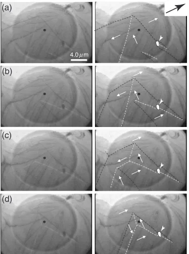
First, we applied the AC magnetizing system to observa-tions of the magnetic domain structure in the doubly-oriented electrical steel sheets. Figure 2 shows Lorentz micrographs of the doubly-oriented electrical steel sheet in the AC magnetic field captured from a videotape. The frequency and amplitude of the AC magnetic field are 0.34 Hz and 2.5 kA/m respectively. The frames from (a) to (d) correspond to half of one AC cycle. The left column shows the original pictures, while in the pictures on the right, domain wall contrast and magnetization are indicated by dotted lines and small arrows
4.0 m
µ
(a)
(b)
(d)
(c)
[image:2.595.112.486.70.572.2]respectively. A SiO2precipitate is indicated by an arrowhead.
The direction of the applied magnetic field is indicated by a big arrow at the top right. Going from (a) to (d), it is observed that the domain walls move smoothly, and thus the area of the domain whose magnetization is parallel to the applied magnetic field increases with increasing magnetic field. The domain with magnetization direction anti-parallel to the applied field disappeared in frame (d), and the domains with magnetization direction at 90 degrees with respect to the applied field remained around the precipitate. It should be noted that the domain walls tend to have a linear shape parallel to the axis of easy magnetization.
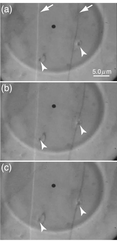
Figure 3 shows the Lorentz micrographs of the
non-oriented electrical steel sheet captured from videotape. The frequency and amplitude of the applied magnetic field are 1.0 Hz and 2.4 kA/m respectively. There are two AlN precipitates observed at the positions indicated by arrow-heads. In the first frame (a), it is seen that the black line corresponding to the domain wall curves around the precipitate, maintain a constant distance from the precipitate. On the other hand, in the second frame (b), it can be noticed that the domain wall jumps into the center of the precipitate, and it does not move under the increasing external magnetic field (the domain wall appearing as white line contrast in the
(b)
(c)
5.0 m
µ
Fig. 3 Lorentz micrographs of the non-oriented electrical steel sheet in the AC magnetic field (1.0 Hz, 2.4 kA/m) captured from a videotape. Domain wall contrasts and two AlN precipitates are indicated by arrows and arrowheads respectively.
(b)
(c)
[image:3.595.48.289.68.564.2] [image:3.595.326.527.71.573.2]left moves significantly from frame (a) to (b)). It is considered that the strain field around the precipitate strongly affected the motion of the domain wall.
Figure 4(a) shows a Lorentz micrograph obtained using the CCD camera, showing a sharper image contrast compared to the images captured from the videotape, as shown in Figs. 2 and 3. The field of view is a part of the area shown in Fig. 3. Figures 4(b) and (c) are Lorentz micrographs ob-served under the two-beam condition of the bright field image. Under this condition, the contrast of the strain field around the precipitates and many dislocations are enhanced,
and thus the positions of these defects are clearly specified. When an AC magnetic field (sine wave 1.0 Hz, 2.4 kA/m) is applied, it is observed that the domain walls are trapped at not only the precipitates (a), but also by their strain fields (b).
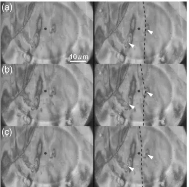
Figure 5 shows Lorentz micrographs under an AC mag-netic field in the same diffraction condition as in Figs. 4(b) and (c). The left column shows the original pictures, while in the pictures on the right, domain wall contrast and precip-itates are indicated by a dotted line and an arrowhead respectively. In the first frame (a), the domain wall is located at the center of the precipitate with changing magnetic field.
(a)
(b)
(c)
10 m
µ
Fig. 5 Lorentz micrographs under an AC magnetic field (1.0 Hz, 2.4 kA/m) in the same diffraction condition as in Figs. 4(b) and (c). In the pictures on the right, a domain wall contrast and two AlN precipitates are indicated by dotted line and arrowheads respectively.
[image:4.595.112.486.71.441.2] [image:4.595.115.483.500.601.2]move through dislocations easily with little friction. Finally, an AC magnetizing experiment with a higher frequency was carried out using the present system. Figure 6 shows the Lorentz microscope image of the non-oriented electrical steel sheet with a magnetic field (a) and the field with opposite direction (b), while (c) corresponds to the image with an AC magnetic field (rectangular wave 40 Hz, 3.2 kA/m). In Figs. 6(a) and (b), it is seen that one bright line corresponding to a magnetic domain wall is shifted by the applied field of opposite direction while in (c), bright lines are observed in both positions as indicated by the arrows due to the AC. It is thus found that dynamic observations are possible currently in the frequency range up to kHz.
4. Conclusion
By utilizing an AC magnetizing system, the dynamic motions of the magnetic domain walls of electrical steel sheets were observed. The following results were obtained.
(1) Stable images were observed by applying the AC
precipitates and dislocations were clearly visualized, and thus, details of interaction between domain walls and strain fields were revealed in the non-oriented electrical steel sheets.
(4) Dynamic observations were extended to the frequency range up to kHz which is useful to evaluate the magnetic properties of electrical steel sheets.
REFERENCES
1) Z. Akase, Y. G. Park, D. Shindo, T. Tomida, H. Yashiki and S. Hinotani: Mater. Trans.46(2005) 974–977.
2) G. Yi, W. A. P. Nicholson, C. K. Lim, J. N. Chapman, S. McVite and C. D. W. Wilkinson: Ultramicrosc.99(2004) 65–72.
3) J. Grundmayer and J. Zweck: Proc. 16th International Microscopy Congress (International Federation of Societies of Microscopy 2006) pp. 1541.
4) T. Tomida: Mater. Trans.44(2003) 1096–1105.