Microstructure of Cr
V
Mo Steel Processed by Recrystallization
and Partial Melting and Its Effect on Mechanical Properties
Yi Meng, Sumio Sugiyama and Jun Yanagimoto
Institute of Industrial Science, The University of Tokyo, Tokyo 153-8505, Japan
Recrystallization and partial melting (RAP) experiments were conducted on CrVMo steel using a multistage hot compression test machine. The dendritic microstructure of the cast material was refined owing to the recrystallization and austenization that occurred during RAP. The refinement of the microstructure is affected by the preparation of the initial cast billet. A higher cooling rate during casting results in afiner RAP-processed globular microstructure. Owing to the core segregation during casting and the phase segregation during RAP, alloying elements are distributed inhomogeneously in RAP-processed specimens. Optimal post heat treatments were designed to increase the homogeneity of the microstructure of RAP-processed specimens. Quenching from 1323 K followed by tempering at 833 K improve the consistency of the Vickers hardness, toughness, and high-temperature wear resistance of RAP-processed specimens. [doi:10.2320/matertrans.M2013398]
(Received October 23, 2013; Accepted March 18, 2014; Published April 25, 2014)
Keywords: recrystallization and partial melting process, tool steel, microstructure, mechanical properties
1. Introduction
To reduce environmental impact, a short process chain for metal manufacturing with lower energy consumption is required. Semisolid process (SSP) technology invented in the 1970s,1)can be employed to design a process chain for metal manufacturing requiring less time and less energy consump-tion. According to the review by Kiuchi and Kopp, after processing a metal by recrystallization and partial melting (RAP) or strain-induced melt activation (SIMA), which were developed on the basis of the SSP, the metal in the semisolid state exhibits various superior characteristics, such as a globular microstructure, adjustable fluidity, and controllable viscosity.25) Compared with conventional casting and forging, SSP technology has greater potential to be used as a core technology for establishing a short process chain.6)
In our previous study, a short process chain for the tool steel production process was preliminarily designed on the basis of RAP technology.7)However, several problems with this process chain must be solved, including the selection of suitable tool materials and the development of equipment to realize large-scale automatic production. Also, a method of inhibiting the inhomogeneous microstructure resulting from phase segregation during the SSP is strongly required.8,9) This requirement was confirmed in our past investigation.10) The inhomogeneous microstructure of ferrous alloys processed by the SSP has a negative effect on the mechanical properties of products. Several studies had been carried out to investigate and inhibit the phase segregation of SSP-processed ferrous alloys. Li et al.pointed out that the phase segregation of ferrous alloys processed by SSP is affected by process parameters such as temperature and strain rate.11) Ferrous alloys contain various semisolid microstructures with different liquid fractions at various temperatures owing to the complicated microstructural evolution during remelting. Considerable phase segregation occurs when a semisolid slurry with a higher liquid fraction is deformed at a lower strain rate.12)Post heat treatments have also been employed to improve the quality of SSP processed ferrous alloys. Uhlenhaut et al. found that different microstructural evolu-tions of SSP-processed X210CrW12 tool steel occurred
under various post heat treatments.13) By adjusting the cooling rate and isothermal aging time in the post heat treatments, a multiphase microstructure with excellent me-chanical properties was realized. The same method was employed by Püttgen et al. to treat SSP-processed 100Cr6 bearing steel. Unfortunately, phase segregation was not prevented by the above post heat treatments.14) The SSP-processed 100Cr6 bearing steel always exhibited poor mechanical properties owing to its inhomogeneous micro-structure before and after post heat treatments. Püttgenet al.
pointed out that the selection of a suitable metal for SSP is one of the main challenges of further research.15)
With the aim of establishing an effective subsequent heat treatment strategy to improve the mechanical properties of products manufactured by RAP, the effects of the preparation of the starting material and post heat treatments on a RAP-processed ferrous alloy were investigated experimentally. The microstructural evolution of cast CrVMo steel was investigated under various experimental conditions. Me-chanical properties such as the Vickers hardness, Charpy impact energy, and resistance at high temperature were obtained experimentally to determine the effects of inhomo-geneous and homoinhomo-geneous microstructures on the mechani-cal properties of RAP-processed CrVMo steel.
2. Experiments
2.1 Materials
Commercial SKD61 tool steel was used. The chemical composition of SKD61 steel is listed in Table 1. The semisolid temperature range of SKD61 is between 1591 and 1762 K. To investigate the effect of the cooling rate during casting, SKD61 steel was melted in an induction furnace and cast into two types of mold as shown in Table 2.
Table 1 Chemical composition of commercial SKD61 tool steel used in experiments, (mass%).
C Si Mn P S Cu Ni Cr V Mo Fe
Two types of cast billet, which was subjected to the different cooling rates as shown in Table 2, were machined into rectangular specimens with a size of 50 mm©20 mm© 10 mm by wire-electric discharge machining.
2.2 RAP experiments and post heat treatment
The RAP process contains two stages, warm predeforma-tion and partial melting. RAP experiments were conducted using a multistage hot compression testing machine, which was used in our previous investigations.7,16) Schematic diagrams of the RAP experimental setup and the dimensions of the dies are shown in Fig. 1. In warm deformation stage, the center part of the specimen was compressed at 573 K with a height reduction of 50%. In the partial melting stage, the compressed specimen was heated to 1668 K and held isothermally for 20 s, then quenched by cold water. Detailed information on the RAP experimental procedure is given in our previous report.7)
In the post heat treatment stage, a resistance furnace was used. First, the RAP-processed specimen was annealed at 1123 K for 3 h then cooled slowly in the furnace. Second, the specimen was quenched from 1323 K after isothermal holding for 480 s and cooled in air. Finally, the specimen was tempered by two passes at 833 K for 2 h then cooled in air. A schematic diagram of the heat treatment strategy is shown in Fig. 2. Detailed information on the heat treatments is given in our previous report.16)
2.3 Measurement of mechanical properties
A Shimadzu Vickers hardness tester was employed to measure the Vickers hardness of the specimens using a load of 0.2 kg and a dwell time of 10 s. In accordance with ASTM E23-04, impact tests were carried out at room temperature to measure the impact energy of the specimens. The RAP-processed specimens subjected to predeformation in the
width direction were cut into Charpy V-notch impact specimens, as shown in Fig. 3.
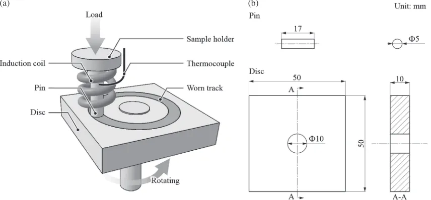
A pin-on-disc rotating-type machine, as shown in Fig. 4, was used to evaluate the high-temperature wear resistance of the specimens. The pins were machined from specimens processed under various experimental conditions. The contact surfaces of the pins were at the geometric center of the specimens. The discs were made of SS400 steel with hardness of 150 HV. The high-temperature wear tests were performed at 600°C for 30 min under a load of 500 N. The rotating speed and the load on the pin were 1280 mm/min and 500 N, respectively.
2.4 Observation of microstructure
[image:2.595.58.537.68.225.2]After polishing and etching in 10% nitric acid/alcohol solution, the specimens processed under various experimental conditions were observed using a Keyence VH-5500 optical microscope. The primary dendrite arm spacing (DAS), the secondary dendrite arm spacing (SDAS) of the cast structure, and the grain size of the RAP-processed specimens were estimated using Scandium image analysis software. The distribution of alloying elements in the specimens was Table 2 Characteristics of molds and measured cooling rates of cast billets
in various casting processes.
Mold
number Material
Dimensions (diameter,D/mm and
height,H/mm)
Cooling rate,
R/K·s¹1
1 Alumina 180 and 200 2.13
2 Graphite 26 and 150 31.21
(a) (b) (c)
Fig. 1 Schematic diagrams of experimental setup of warm deformation (a), partial melting (b) and dimensions of dies (c).
Fig. 2 Schematic diagram of heat treatment strategy.
[image:2.595.308.546.266.368.2] [image:2.595.45.292.286.349.2] [image:2.595.330.520.405.477.2]investigated by energy-dispersive X-ray spectroscopy (EDS). The impact fracture and worn surfaces of the specimens were observed using a JEOL JSM-5600 scanning electron mi-croscopy (SEM) system.
3. Experimental Results and Discussion
3.1 Microstructural evolution during RAP
The microstructures of specimens prepared in mold 1 in various stages of the RAP process are shown in Fig. 5. The cast billet exhibits a coarse dendritic structure, as shown in Fig. 5(a). Carbides and impurities are inhomogeneously distributed in the interdendritic regions. This inhomogeneous microstructure of the cast material, known as core segrega-tion, is attributed to the solidification of the dendritic mode in the molten metal. During casting, metals with a high melting point solidify and grow in the dendritic mode, and alloying elements and impurities accumulate in the interdendritic regions. When the cooling rate is lower, a coarse micro-structure with a more inhomogeneous distribution of alloying elements is obtained.
After warm predeformation, the plastic deformation of grains occurred along the forming direction, as shown in Fig. 5(b). However, no recrystallization took place to change the grain size. Owing to the absence of diffusion, the alloying elements and impurities remained distributed in the inter-dendritic regions.
In the remelting stage, recrystallization and austenitzation occurred when the temperature of the specimen was above the recrystallization and austenitization temperatures of the CrVMo tool steel, respectively. Recrystallized grains and some carbides or impurities located at grain boundaries can be observed in Fig. 5(c). Note that the recrystallized grains near the carbides or impurities are always smaller than the elsewhere. The carbides or impurities provided positions for nucleation during recrystallization and acted as obstacles during grain growth.
When the temperature exceeded the solidus temperature, the grain boundary regions melted first owing to the release
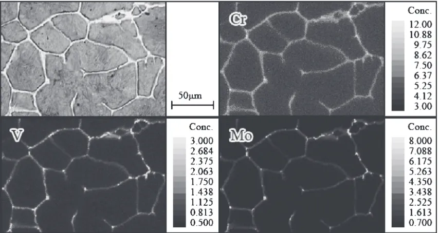
of forming energy stored in these regions during predefor-mation. Because of the lower melting points of the regions rich in alloying elements partial melting also took place in these regions. As shown in Fig. 5(d), a microstructure containing discrete spherical solid particles surrounded by a liquid-phase network was obtained after isothermal holding at 1668 K for 20 s. According to the result of EDS shown in Fig. 6, more alloying elements were distributed in former liquid-phase areas of the RAP-processed specimens than elsewhere. This was attributed to the melting of regions rich in alloying elements. Owing to the melting of grain boundaries, impurities were also located in the former liquid-phase areas. The inhomogeneous distribution of alloying elements in the RAP-processed specimens originated from the core segregation that occurred during casting, then rearranged by the formation of an interconnected liquid-phase network during partial remelting.
The specimens machined from the billet which cast in the smaller graphite mold, which were cooled much more rapidly during casting, were also subjected to RAP. The micro-structures of the specimens before and after RAP are shown in Fig. 7. The results of the quantitative microstructural analysis of the specimens processed under various exper-imental conditions are listed in Table 3.
The finer dendritic microstructure shown in Fig. 7(a) is attributed to the higher cooling rate during casting. The higher cooling rate reduced the solidification time and inhibited the coarsening of the dendritic structure. The alloying elements were distributed more homogeneously in the cast specimens with the higher cooling rate owing to the finer dendritic structure. The finer microstructure of the starting material resulted in smaller solid particles and afiner liquid-phase network as shown in Fig. 7(b). Consistent with our previous description, the alloying elements were mainly distributed in the finer liquid-phase network.16) Thus, the high cooling rate during casting resulted in a finer RAP-processed microstructure and a more homogeneous distribu-tion of the alloying elements.
(a) (b)
[image:3.595.86.514.73.272.2]3.2 Microstructural evolution during post heat treat-ment
The aim of post heat treatment is to cause the evolution of the microstructure and homogenize the distribution of alloy elements in RAP-processed specimens. SEM images and
Results of line analysis of RAP-processed specimens subjected to various heat treatments are shown in Figs. 8 and 9, respectively.7)
In the annealed specimen, the former solid particles and the former liquid phases surrounding them exhibit various Fig. 5 Microstructures of as cast specimen (a), the warm predeformed specimen at room temperature (b), the warm predeformed specimen
partial remelted at 1423 K (c), and the warm predeformed specimen partial remelted at 1668 K (d). Impurities and carbides are indicated by black arrows.
[image:4.595.96.497.68.393.2] [image:4.595.86.513.450.677.2]microstructural morphologies. The following empirical equation was used to estimate the martensite start temperature based on the contents of the alloying elements:
Ms¼908475wC17wCr33wMn; ð1Þ
whereMsis the martensite start temperature,wCis the carbon content, wCr is the chromium content, and wMn is the manganese content; the unit is K.17)
Owing to the various contents of the alloying elements in the former solid-phase and liquid-phase areas of the RAP-processed specimens, various microstructural evolutions occurred during the quenching treatment. The lower content of the alloying elements in the former solid-phase areas resulted in a higher martensite start temperature. Sufficient martensite transformation resulted in the martensite structure.
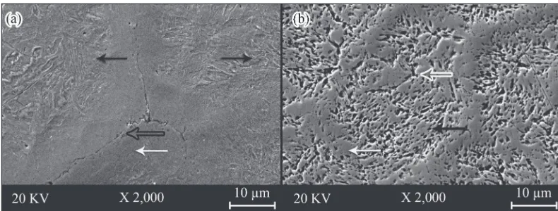
However, the higher content of the alloying elements in the former liquid-phase areas resulted in a lower martensite start temperature in these areas. No martensite and only retained austenite and chainlike carbides were observed in the former liquid-phase areas. The microsegregation of the RAP-processed specimens still existed after the quenching treat-ment. A microstructure containing martensite surrounded by an intergranular network of retained austenite accompanied by chainlike carbides on the grain boundaries is shown in Fig. 8(a). The existence of chainlike carbides resulted in the inhomogeneous distribution of alloying elements, as shown in Fig. 9(a).
[image:5.595.100.496.69.232.2]Tempering treatments at 833 K were conducted to reduce the residual stress, weaken the phase segregation of the RAP-processed specimens, and hence homogenize the distribution of alloying elements. As shown in Fig. 8(b), the precipitation of secondary carbides and the coarsening of martensite occurred in the former solid-phase areas. The diffusion that occurred in the former liquid-phase areas changed the morphology of the carbides and reduced the content of alloying elements in the retained austenite. The lower content of alloying elements in the retained austenite increased the martensite start temperature and resulted in martensite in the former liquid-phase areas. Thus, the tempered specimens consisted of tempered martensite and secondary carbides in the former solid-phase areas, and newly formed martensite, Fig. 7 Microstructure of specimens cast in smaller graphite mold before RAP process (a) and after RAP process (b).
Table 3 Results of quantitative analysis of microstructure of specimens processed under various experimental conditions.
Mold number
Before RAP process After RAP
process
Primary dendrite arm spacing,DAS/µm
Secondary dendrite arm spacing,SDAS/µm
Size of solid particles,S/µm
1 385«81.5 121«13.4 41«17.8
2 115«21.5 21«3.5 19«2.5
[image:5.595.99.494.265.415.2] [image:5.595.49.292.503.577.2]retained austenite, and carbides in the former liquid-phase areas. The homogeneity of the alloying-element distribution was improved by the tempering treatments, according to the results of line analysis shown in Fig. 9(b). In the light of the presented results and discussion, a schematic illustration of microstructural evolution during RAP and post heat treat-ments is shown in Fig. 10.7)
3.3 Mechanical properties
The mechanical properties of cast CrVMo steel processed under various experimental conditions are listed in Table 4, in which those of commercial hot-rolled SKD61 are given for reference. The impact fracture and worn surfaces of specimens subjected to various treatments are shown in Figs. 11 and 12, respectively.
In comparison with the tempered specimen and the commercial rolled SKD61, the quenched specimen exhibited higher hardness. It was attributed to the large residual stress stored inside the martensite during the transformation from austenite with a face-centred cubic (FCC) structure to ferrite with a body-centred cubic (BCC) structure.18) However, the lack of martensite in the former liquid-phase areas resulted in the lower hardness of these areas. Thus, the inhomogeneous microstructure of the RAP-processed specimens after quenching treatment caused the inhomogeneous hardness, which was reflected in the standard deviation of the Vickers hardness shown in Table 4. Tempering treatment at 833 K increased the inhomogeneity of the microstructure, as
described in Section 3.2, and led to a lower standard deviation of the Vickers hardness, in comparison with the quenched specimen. According to our previous study,19) tempering treatment at a low temperature (200673 K) leads a rapid decrease of the hardness due to the release of the residual stress in martensite. However, when the tempering temperature increased to 833 K, tempering of martensite and secondary hardening occurred simultaneously and resulted in a slight decrease of hardness. Thus, tempering treatment at 833 K reduced the hardness of a RAP-processed specimen slightly but increased the homogeneity of the hardness.
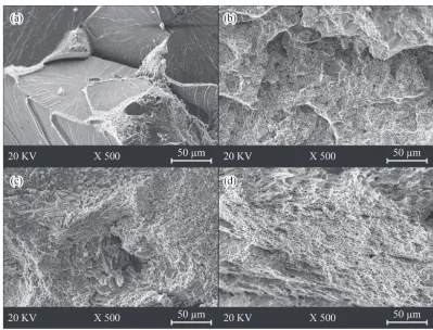
The low impact energy reflects the low toughness of the as cast CrVMo steel. The large intergranular fractures with large cleavage planes were observed on the impact fracture surface of the as cast specimen, as shown in Fig. 11(a). The Fig. 9 Results of line analysis of RAP-processed CrVMo specimens quenched from 1323 K (a) and then tempered at 833 K (b);
[image:6.595.131.466.68.404.2]chainlike carbide is indicated by black arrow, and carbides are indicated by white arrows.7)
Table 4 Mechanical properties of CrVMo steel specimens subjected to various treatments.
Treatments
Vickers hardness,
Hv/HV
Impact energy,
Ie/J
Wear volume,
Wv/mm3
Commercial hot-rolled 567«30 75.0«3.0 2.99«0.29
As-cast 823«30 3.2«0.5 8.55«0.31
RAP and quenching (1232 K) 738«80 13.5«2.0 5.72«0.53 RAP and quenching (1232 K)
[image:6.595.305.548.477.572.2]quenched specimen also exhibited a low impact energy, in comparison with the specimen tempered at 833 K and the commercial rolled SKD61. As shown in Fig. 11(b), trans-granular fractures with cleavage planes were observed on the impact fracture surface of the quenched specimen. The high
residual stress stored in the martensite and the brittle chainlike carbides along the former liquid films resulted in this result in impact tests, according to the work of Püttgen
[image:7.595.59.536.83.346.2]et al.14)The tempering treatment changed the morphology of the carbides, reduced the residual stress inside the martensite, Fig. 10 Schematic illustration of microstructural evolution during RAP and post heat treatments.7)
[image:7.595.97.496.378.682.2]and rearranged the retained austenite. The microstructural evolution that occurred during the tempering treatment resulted in the higher impact energy of the RAP-processed specimen. As shown in Fig. 11(c), the smaller cleavage planes mixed with small dimples on the fracture surfaces of the tempered specimen indicated its improved toughness. Onlyfiner dimples were observed on the fracture surfaces of commercial rolled SKD61 tool steel, as shown in Fig. 11(d). As shown in Fig. 12, both abrasive wear tracks and adhesive layers were observed on all the worn surfaces of the specimens. Owing to the abrasive wear under the dry sliding condition, particles were chipped from the surfaces of the specimens. The heat generated by the friction caused cold welding at the interface between the pin and the disc, and created the adhesive layers. The work hardening of the adhesive layers resulted in spalling and the formation of microcracks at the interfaces of the specimens. According to the work of Hanlon and Rainforth,20)fractures always occur along the interfaces between the carbides and the matrix. Considerable surface degradation occurred on the surface of the cast specimen owing to its network of the coarse interdendritic carbides, as shown in Fig. 12(a). Although the hardness of the martensite structure in the quenched speci-men is reasonably high, the brittle interconnected chainlike carbides in the former liquid-phase areas cause surface degradation similar to that of the cast specimen. Compared with the quenched specimen shown in Fig. 12(b), the tempered specimen contained more tempered martensite with lower residual stress and smaller discrete carbides. It also had a higher high-temperature wear resistance and exhibited a worn surface with less degradation, as shown in Fig. 12(c).
As a reference, commercial rolled SKD61 tool steel shown in Fig. 12(b) exhibited excellent high-temperature wear resistance.
As described above, the poor mechanical properties of as cast CrVMo steel were attributed to the coarse inhomoge-neous microstructure of it. RAP process and the subsequent heat treatments refined the microstructure and improved the mechanical properties. The feasibility of the process chain for tool steel manufacturing based on RAP technology was verified experimentally. However, even after subsequent heat treatments, the mechanical properties of RAP-processed Cr VMo steel were inferior to those of the commercial rolled SKD61 tool steel. This proposed process chain needs to be improved by some new methods, such as hot working following the RAP process.
4. Conclusion
The main results in this work are summarized as follows. (1) The inhomogeneous distribution of alloying elements in the RAP-processed specimens was attributed to the core segregation during casting and phase segregation during partial remelting.
(2) A higher cooling rate during casting resulted in a RAP-processed specimen with a finer microstructure and a more homogeneous distribution of alloying elements owing to the finer microstructure of the starting material.
[image:8.595.98.496.69.367.2](3) Post heat treatments caused the microstructural evolu-tion of the RAP-processed specimen, and caused the more homogeneous distribution of alloying elements. Fig. 12 SEM images of worn surfaces of as cast specimen (a), RAP processed specimen after quenching treatment at 1323 K (b), RAP
(4) Tempering treatment at 833 K reduced the residual stress, modified the morphology of chainlike carbides in the quenched specimens, and improved the toughness and high-temperature wear resistance.
(5) The feasibility of the process chain for tool steel manufacturing based on RAP technology was verified. Further studies are required to improve the quality of product manufactured by this process chain.
Acknowledgments
This study wasfinancially supported by a Grant-in-Aid for Scientific Research on the Innovative Area “Bulk Nano-structured Metals” through MEXT, Japan (contract No. 22102005).
REFERENCES
1) M. C. Flemings:Metall. Trans. A22(1991) 957981. 2) M. Kiuchi and R. Kopp:CIRP Ann.51(2002) 653670. 3) H. Atkinson and D. Liu:Mater. Sci. Eng. A496(2008) 439446. 4) D. Kirkwood, C. Sellars and L. Eliasboyed: US Patent (1991)
5,037,498.
5) K. Young, C. Kyonka and J. Courtois: US Patent (1983) 4,415,374.
6) M. Kiuchi, J. Yanagimoto and H. Yokobayashi:CIRP Ann.50(2001) 157162.
7) Y. Meng, S. Sugiyama and J. Yanagimoto:J. Mater. Process. Technol. 214(2014) 8796.
8) W. Püttgen, W. Bleck, I. Seidl, R. Kopp and C. Bertrand:Adv. Eng. Mater.7(2005) 726735.
9) S. Chayong, H. Atkinson and P. Kapranos:Mater. Sci. Eng. A390 (2005) 312.
10) Y. Meng, S. Sugiyama and J. Yanagimoto:J. Mater. Process. Technol. 212(2012) 17311741.
11) J. Li, S. Sugiyama, J. Yanagimoto, Y. Chen and W. Guan:J. Mater. Process. Technol.208(2008) 165170.
12) J. Li, S. Sugiyama and J. Yanagimoto:J. Mater. Process. Technol.161 (2005) 396406.
13) D. Uhlenhaut, J. Kradolfer, W. Püttgen, J. Löffler and P. Uggowitzer: Acta Mater.54(2006) 27272734.
14) W. Püttgen, B. Hallstedt, W. Bleck, J. Löffler and P. Uggowitzer:Acta Mater.55(2007) 65536560.
15) W. Püttgen, W. Bleck, G. Hirt and H. Shimahara:Adv. Eng. Mater.9 (2007) 231245.
16) Y. Meng, S. Sugiyama, M. Soltanpour and J. Yanagimoto:J. Mater. Process. Technol.213(2013) 426433.
17) H. Finkler and M. Schirra: Steel Res. Int.67(1996) 328342. 18) G. Totten, M. Howes and T. Inoue:Handbook of Residual Stress and
Deformation of Steel, (ASM International, OH, United States, 2002) pp. 232234.
19) E. Smith:Acta Mater.14(1966) 583593.