2018, Volume 5, e4267 ISSN Online: 2333-9721 ISSN Print: 2333-9705
DOI: 10.4236/oalib.1104267 Feb. 9, 2018 1 Open Access Library Journal
Design of Drive System for Sensorless
Brushless DC Motor Based on Model Reference
Adaptive Control and Its Application in
Horizontal Well Tractor
Zhou He, Yongjun Chen
*, Bo Ruan, Shuhan Yu, Junwen Zhou
College of Electronics and Information, Yangtze University, Jingzhou, China
Abstract
The actual working environment temperature of the horizontal well tractor is too high, which leads to position sensor of general brushless DC motor (BLDCM) cannot work normally. Therefore, the position sensorless drive system is designed to overcome the problems caused by the position sensor in the actual working conditions. The principle of sensorless BLDCM work is introduced in detail, And drive system of Sensorless BLDCM was established by using simulation software. The use of three stage start make motor smoothly start, the motor speed detection based on model reference adaptive control (MRAC), ensures accurate commutation. Finally, the hardware and software design of the BLDCM system based on digital signal controller (DSC) is in-troduced and tested. The experimental results show that the drive system can start the BLDCM smoothly in the high temperature environment, and can quickly track the given speed, which meet the actual work demand of the ho-rizontal well tractor.
Subject Areas
Electric Engineering
Keywords
Horizontal Well Tractor, Brushless DC Motor (BLDCM), Position Sensorless, Model Reference Adaptive Control (MRAC)
1. Introduction
As horizontal well technology is increasingly used in oil and gas development,
How to cite this paper: He, Z., Chen, Y.J., Ruan, B., Yu, S.H. and Zhou, J.W. (2018) Design of Drive System for Sensorless Brushless DC Motor Based on Model Re- ference Adaptive Control and Its Appli- cation in Horizontal Well Tractor. Open Access Library Journal, 5: e4267.
https://doi.org/10.4236/oalib.1104267 Received: December 18, 2017 Accepted: February 6, 2018 Published: February 9, 2018
Copyright © 2018 by authors and Open Access Library Inc.
This work is licensed under the Creative Commons Attribution International License (CC BY 4.0).
http://creativecommons.org/licenses/by/4.0/
DOI: 10.4236/oalib.1104267 2 Open Access Library Journal
horizontal well tractors have been proposed as a new type of downhole motion device. It can meet the delivery of logging tools and auxiliary work such as per-foration and fishing to solve the problem that the instrument is difficult to be transported to a predetermined position in the downhole and horizontal wells by gravity.
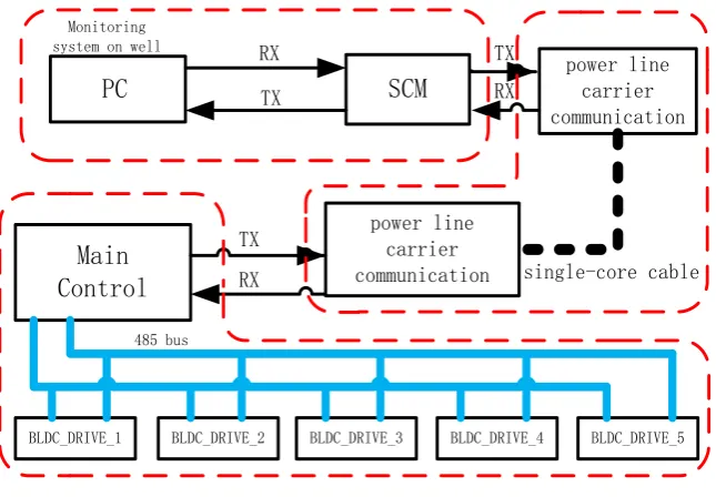
Brushless DC Motor (BLDCM) is a new mechatronic product with many ad-vantages such as stable structure, high power density, high efficiency, easy main-tenance, long life and easy driving. It has been widely used in the fields of aero-space, automotive, robotics, household appliances and medical devices. There-fore, BLDCM has been chosen as drive motor of horizontal well tractor. The overall structure of the horizontal well tractor is shown in Figure 1.
However, due to the too high actual working environment temperature of the horizontal well tractor, the position sensor of general BLDCM cannot work
normally [1][2] [3] [4]. As a result, the general BLDCM will generate wrong
commutation signals in this working environment, which may cause the motor lost step or even block turn. Therefore, the BLDCM used as drive motor of hori-zontal well tractor needs to adopt a positionless driving manner to overcome the problem caused by the position sensor in the actual working condition.
Based on the analysis principle of sensorless BLDCM work, the simulation of drive system for sensorless BLDCM was established by using PSIM simulation
software [5][6]. The use of three stage start make motor smoothly start, the
mo-tor speed detection based on model reference adaptive control (MRAC) [7],
en-sures accurate commutation. Finally, the drive system for sensorless BLDCM was established based on digital signal controller (DSC) and tested. The experimental results show that the drive system can make BLDCM run stably in the high tem-perature environment and meet the actual working conditions of the horizontal well tractor.
SCM
power line carrier communication
Main
Control
BLDC_DRIVE_1 BLDC_DRIVE_2 BLDC_DRIVE_3 BLDC_DRIVE_4 BLDC_DRIVE_5
power line carrier communication RX
TX
single-core cable RX
TX
RX TX
485 bus
PC
[image:2.595.210.533.488.712.2]Monitoring system on well
DOI: 10.4236/oalib.1104267 3 Open Access Library Journal
2. The Principle of Sensorless BLDCM Work
2.1. The Mathematical Model of BLDCM
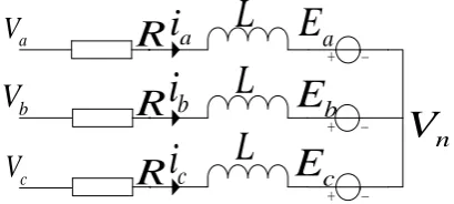
BLDCM selected by horizontal well tractor is star connection and the central node is not led out, its equivalent circuit shown in Figure 2.
According to Kirchhoff’s voltage law, the equation of phase voltage can be ob-tained as follows:
0 0 0 0
d
0 0 0 0
d
0 0 0 0
a a a a n
b b b b n
c c c c n
V R i L i E V
V R i L i E V
t
V R i L i E V
= + × + + (1)
in type: V V Va, b, c—Voltage of each phase to the ground; , ,
a b c
i i i —Phase current;
x e m
E =kω —Back EMF, ke,ωm are back EMF coefficient and rotor
mechani-cal speed;
R—Phase resistance;
s m
L=L −L —Equivalent inductance of stator winding, L Ls, m are self
induc-tance of stator winding and mutual inducinduc-tance between stator winding;
n
V —Central node voltage of motor armature winding.
2.2. Principle of Back EMF Zero Crossing Detection
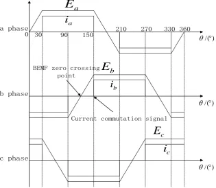
The back EMF of BLDCM is a trapezoidal wave, the current is a square wave, and the phase current of each phase winding must be consistent with the back EMF in order for the BLDCM to output the maximum torque. Therefore, Com-mutation is required for every 60°electric angle in one electric period. Relation of
back EMF and current in BLDCM as shown in Figure 3. It can be seen from
Figure 3 that back EMF zero crossing point leading the current commutation signal 30˚ in each phase winding, So, The commutation time can be got accord-ing to the back-EMF zero crossaccord-ing point. The motor back EMF can not be meas-ured directly, so, It is necessary to calculate the equivalent voltage by phase vol-tage.
Set x phase is the non-conducting phase, the phase current is 0, according to
Equation (1) can be got:
x x n
E =V −V (2)
It can be seen from Equation (2) that the commutation signal can be obtained
+ -+ + -b
V
R
R
R
E
a
[image:3.595.269.474.608.700.2]c
E
bE
nV
ai
c
i
b
i
aV
cV
L
L
L
DOI: 10.4236/oalib.1104267 4 Open Access Library Journal
30 90 150 210 270 330 360 0
a phase
a
E
b
i
c
i
) /(°
θ
) /(°
θ
) /(°
θ
a
i
BEMF zero crossing point
Current commutation signal
c
E
b
E
b phase
[image:4.595.216.532.78.352.2]c phase
Figure 3. Relation diagram of back EMF and current.
indirectly by comparing the relationship between the phase voltage and the cen-tral node voltage.
Since the center node of the motor selected by the drive system is not led out, it is necessary to fabricate the motor central node voltage.
As a BLDCM, there are only two phases which have current at the same time, Due to conducting two-phase current equal to the opposite direction, the other a phase current is 0, from Equation (1) can be got:
3
a b c a b c n
V +V +V =E +E +E + V (3)
It can be seen from Figure 2 that the sum of the three phase back EMF is zero
when the back-EMF zero crossing, so, the central node voltage at this time can be got as:
3 a b c n
V V V
V = + + (4)
3. Simulation and Analysis of Sensorless BLDCM Drive
System Based on PSIM
According to the above analysis, Block diagram of drive system for sensorless
BLDCM shown in Figure 4, the drive system uses speed, current double closed-
loop control.
DOI: 10.4236/oalib.1104267 5 Open Access Library Journal
Speed calculation and
positionless commutation PI
PI Three phase
inverter BLDCM DC
source
PWM controller
ref Spd_
act I_
ref
I_ U
act Spd_
[image:5.595.210.539.68.194.2]Commutation signal
Figure 4. Sensorless BLDCM drive system block diagram.
PSIM to establish drive system of sensorless BLDCM according to Figure 3. The
parameters of the motor are as follows: The stator resistance is 11.9 Ω, the stator inductance is 2.07 mH, the stator mutual inductance is 0.69 mH, the number of
motor pole pairs is 2, the back EMF coefficient is 16.15 V·krpm−1, the moment of
inertia is 0.007 g·m2, the friction coefficient is 1.167 g·m2·s−1, the inverter input
voltage is 300 V, the given speed is 6000 rpm.
3.1. Three Stage Start of Sensorless BLDCM
Since the back EMF increases with the increase of speed, the back EMF zero- crossing detection is not suitable for motor starting. The drive system adopts three stage start algorithm when the motor is starting, namely, the rotor
pre-positioning, external synchronous acceleration, self-synchronization. Figure
5 and Figure 6 are diagrams of rotor position using a three stage start algorithm.
From Figure 5 and Figure 6 shows, the use of three stage start algorithm can
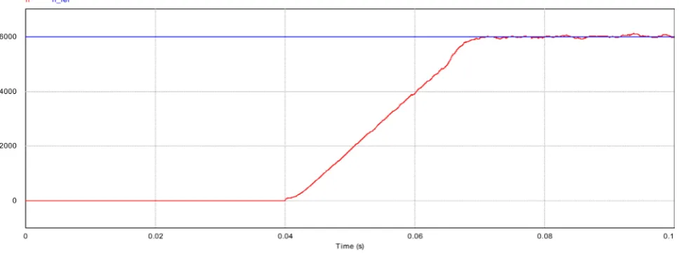
be achieved smooth start of the motor. Figure 7 is the motor speed response
curve.
It can be seen from Figure 7, the use of three stage start algorithm to start, the
speed can be in a relatively short period of time to track the given speed to
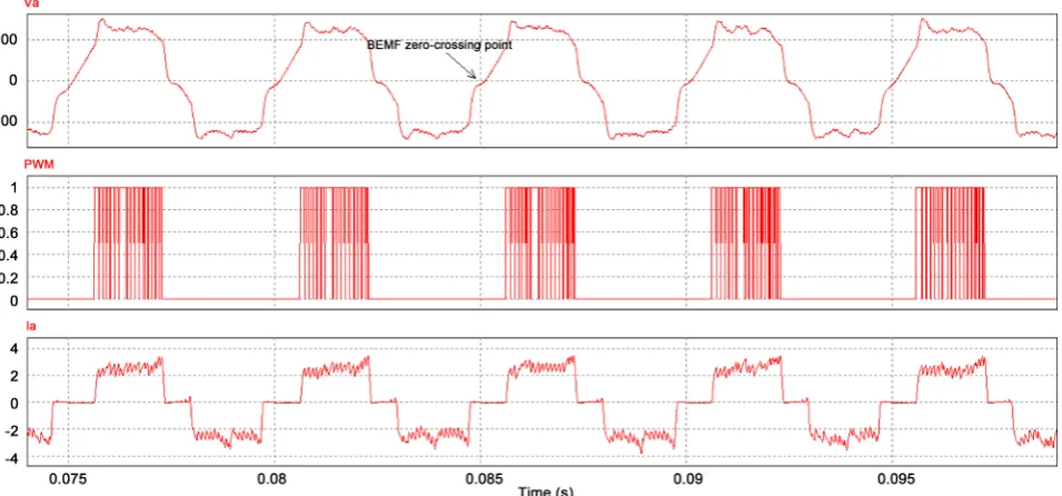
achieve the desired start effect. Figure 8 is the a phase voltage, PWM and current
after switch to self-synchronizing.
Visible, the simulation results consistent with the previous theoretical analysis, the back-EMF zero-crossing lead the phase commutation signal 30˚ electrical angle.
3.2. BLDCM Speed Detection Based on Model
Reference Adaptive Control
DOI: 10.4236/oalib.1104267 6 Open Access Library Journal
[image:6.595.61.543.300.491.2]Figure 5. Diagrams of rotor position with an initial electric angle of 0 degrees.
Figure 6. Diagrams of rotor position with an initial electric angle of 200 degrees.
[image:6.595.59.543.528.710.2]DOI: 10.4236/oalib.1104267 7 Open Access Library Journal
Figure 8. The a phase voltage, PWM and current after switch to self-synchronizing.
necessary to find a more accurate method of speed detection.
For BLDCM, when the current from phase a to phase b is considered. There are following equations:
0
a b
c
a b
i i i
E E
= − =
= −
(5)
According to the formula (1) the line voltage between phase a and phase b can be obtained:
d
2 2 2
d a
ab a b a a
i
V V V Ri L E
t
= − = + +
(6)
In stable condition, d 0
d
i
t≈ . Then, (6) can be rewritten as:
2
2
ab a
m
e
V Ri
k
ω = −
(7)
According to Equation (7), the motor speed can be calculated according to the line voltage and phase current, but the motor windings resistance could change with the change of temperature. Therefore, BLDCM speed detection based on
model reference adaptive control (MRAC) is proposed. As shown in Figure 9.
As can be seen from Figure 9, the main module of speed detection is a model
reference adaptive regulator, Spe est_ is speed estimated by line voltage and
phase current, Spe ce_ is speed calculated by the commutation signal, The
in-put of regulator is the deviation of the two speed, the outin-put of the regulator is a
correction variable quantity kc to estimate the speed.
DOI: 10.4236/oalib.1104267 8 Open Access Library Journal
PI
estS p d_ c
k
ce
Spd_
a i
ab V
e a c ab m
k
Ri
k
V
2
2
[image:8.595.257.471.75.158.2]−
=
ω
Figure 9. BLDCM speed detection based on model reference adaptive.
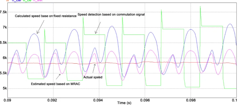
Figure 10. Comparison of several speed detection methods.
speed detected based on the commutation signal and the estimated speed based
on the MRAC are shown in Figure 10.
It can be seen from Figure 10 that after the change of the resistance of the
sta-tor winding of the mosta-tor, the estimated speed based on the MRAC is the closest to the actual speed.
4. Actual Test and Result Analysis of Drive System
for Sensorless BLDCM
4.1. DSC Based Drive System of Sensorless BLDCM
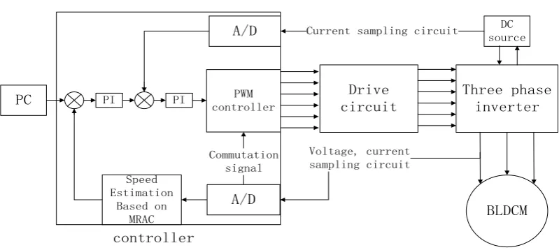
Drive system of sensorless BLDCM includes two parts: software and hardware, the software part includes the main program and several subroutines and inter-rupt service functions, the main function is to achieve BLDCM without position start, commutation, PWM duty cycle setting and communicate with the upper computer. The hardware part includes the controller, drive circuit, three phase inverter, voltage and current sampling circuit. and the overall structure of the
drive system is shown in Figure 11.
[image:8.595.60.532.196.404.2]DOI: 10.4236/oalib.1104267 9 Open Access Library Journal
Drive circuit
Three phase inverter
BLDCM PC
DC source
Voltage, current sampling circuit
A/D PWM controller
A/D Current sampling circuit
PI PI
Speed Estimation
Based on MRAC
Commutation signal
[image:9.595.138.538.63.242.2]controller
Figure 11. The overall structure of the drive system for sensorless BLDCM.
The control chip is a kind of motor-specific control chip with digital signal pro-cessor (DSP) computing function. It can withstand underground high tempera-ture environment and meet the actual working conditions of horizontal well tractors. As the IGBTs that form the three phase inverter need certain voltage and power to trigger, Therefore, a driving circuit composed of the driver chip IR2233 and its corresponding peripheral circuits is added between the controller and the three phase inverter. The specific design of the driving circuit and the inverter circuit is shown in Figure 12.
As the drive system uses PWM technology, which results in a large number of chopping components in the detected voltage and current, which will interfere with the sampling, therefore, It is necessary to add a filter capacitor in the sam-pling circuit.
As can be seen from Figure 11, the drive system uses double closed-loop
speed and current control, the controller receives commands through the com-munication with the upper computer to obtain the desired speed of the motor, after the motor is started and switched to self-synchronous by the three stage start algorithm, Estimate the actual motor speed based on MRAC, DC bus cur-rent obtained through the curcur-rent sampling circuit, and then through the speed regulator and current regulator to obtain the corresponding PWM duty cycle, so that the motor speed reaches the desired speed.
DOI: 10.4236/oalib.1104267 10 Open Access Library Journal Q3 IRG4PH30KD Q5 IRG4PH30KD Q6 IRG4PH30KD Q4 IRG4PH30KD Q1 IRG4PH30KD Q2 IRG4PH30KD H1 H2 H3 L1 L2 L3 12V ITRIP+ 1 F-CLR 2 VSS 7 COM 8 LO3 9 LO2 10 LO1 11 VS3 12 HO3 13 VB3 14 VS2 15 HO2 16 VB2 17 VS1 18 HO1 19 VB1 20 HIN1 22 HIN2 23 HIN3 24 LIN1 25 LIN2 26 LIN3 27 VCC 21 SD 6 FAULT 28 CAO 3 CA+ 5 CA-4 U6 IR2233 10R R37 10R R35 10R R33 10R R31 100nF C31 10K R41 2K R42 100nF C32 10R R38 10R R39 47R R40 10K R43 20K R44 MLIN A B C 6.8uF C30 6.8uF C44 6.8uF C43 6.8uF C42 47uF/35V C33 C34 47n/1000V C35 47n/1000V C36 47n/1000V MGND FAULT MGND MGND D17 UF4007 D18 UF4007 D19 UF4007 Rin 1 Rout 4
Min 2 Mout 3
[image:10.595.68.530.82.515.2]R69 MGND GND D29 2.7V I_MCU ITRIP R61 10k R62 10k 100nF C37 100nF C38 GND 1nF C39
Figure 12. Design of specific driving circuit and inverter circuit.
4.2. Experimental Results and Analysis
The structure of the body, rotor and stator of the motor used in the drive system
are shown in Figure 13 and Figure 14.
In order to facilitate the test of the drive system, we designed a monitoring and control software for upper computer based on the serial port, which can monitor
the motor speed and PWM duty cycle. Figure 15 shows the Phase voltage
wave-form diagram before and after filtering. Figure 16 the modulation signal of the
upper bridge and phase voltage waveform. Figure 17 and Figure 18 are motor
speed and PWM duty cycle obtained by the software at a temperature of 150˚C.
DOI: 10.4236/oalib.1104267 11 Open Access Library Journal
[image:11.595.290.463.189.292.2]Figure 13. Structure diagram of motor body.
Figure 14. Structure diagram of rotor and stator.
Figure 15. Phase voltage waveform diagram before and after filtering.
[image:11.595.252.494.321.497.2] [image:11.595.253.494.526.705.2]DOI: 10.4236/oalib.1104267 12 Open Access Library Journal
Figure 17. Motor speed.
Figure 18. Pwm duty cycle.
DOI: 10.4236/oalib.1104267 13 Open Access Library Journal
From the experimental results, it can be seen that the drive system for sensor-less BLDCM based on DSC can realize the smooth start of BLDCM in high tem-perature environment and can track the given speed rapidly.
5. Conclusion
In this paper, based on the analysis of BLDCM for horizontal well tractor, a drive system of sensorless BLDCM for horizontal well tractor is designed, which uses three stage start algorithms and speed detections based on model adaptive con-trol. The simulation and experimental results show that the drive system can make the BLDCM start and run smoothly in the high temperature environment and can track the given speed quickly to meet the actual working requirements of the horizontal well tractor.
References
[1] Yu, S.H. and Chen, Y.J. (2017) A New Strategy for BLDC Sensorless Control System and Its Application in Horizontal Well Tractor. Open Access Library Journal, 4, e3844. https://doi.org/10.4236/oalib.1103844
[2] Chen, S.H., Liu, G., Zheng, S.Q., et al. (2017) Sensorless Control of BLDCM Drive for a High-Speed Maglev Blower Using Low-Pass Filter. IEEE Transactions on Power Electronics, 32, 8845-8856. https://doi.org/10.1109/TPEL.2016.2645782 [3] Lai, Y.-S. and Lin, Y.-K. (2011) A Unified Approach to Zero-Crossing Point
Detec-tion of Back EMF for Brushless DC Motor Drives without Current and Hall Sen-sors. IEEE Transactions on Power Electronics, 26, 1704-1713.
[4] Wang, H.-P. and Liu, Y.-T. (2006) Integrated Design of Speed-Sensorless and Adaptive Speed Controller for a Brushless DC Motor. IEEE Transactions on Power Electronics, 21, 518-523. https://doi.org/10.1109/TPEL.2005.869772
[5] Xia, C.L. and Li, X.M. (2015) Z-Source Inverter-Based Approach to the Zero- Crossing Point Detection of Back EMF for Sensorless Brushless DC Motor. IEEE Transactions on Power Electronics, 30, 1488-1498.
[6] Wang, H.-B. and Liu, H.-P. (2009) A Novel Sensorless Control Method for Brush-less DC Motor. IET Electric Power Applications, 3, 240-246.
[7] Liu, Y., Zhao, J., Xia, M., et al. (2014) Model Reference Adaptive Control-Based Speed Control of Brushless DC Motors with Low-Resolution Hall-Effect Sensors.