INTRODUCTION
Insects possess a remarkable repertoire of sophisticated aerobatic behaviours such as centring and escape responses, collision avoidance, and an elaborate landing programme (for a review, see Egelhaaf and Kern, 2002). Previous research has shown that, especially in flies, aerial manoeuvres require elaborate sensory feedback from the gyroscopic halteres, the campaniform sensilla on the wings or the compound eyes (Chan and Dickinson, 1996; Dickinson and Palka, 1987; Fayyazuddin and Dickinson, 1996; Hengstenberg, 1988; Götz, 1980; Nalbach, 1994). Over the years, the interplay between sensory stimuli and the formation of motor commands for flight control has been thoroughly investigated on different levels covering electrical recordings from motion-sensitive neurons (Borst and Egelhaaf, 1989; Egelhaaf and Borst, 1993; Franceschini et al., 1989; O’Carroll, 1993; Warzecha et al., 1992), the flight musculature under tethered flight conditions (Balint and Dickinson, 2001; Egelhaaf, 1989; Götz, 1983; Heide and Götz, 1996; Heide et al., 1985; Lehmann and Götz, 1996; Tu and Dickinson, 1996), and experiments on flight behaviour in tethered and free flight under a great variety of stimulus conditions (Ennos, 1989; Frye and Dickinson, 2001; Götz, 1987; Heisenberg and Wolf, 1988; Heisenberg and Wolf, 1993; Tammero and Dickinson, 2002a; Wagner, 1985; Wolf et al., 1995; Wolf and Heisenberg, 1990).
Early studies on flight control (e.g. Blondeau and Heisenberg, 1982; Götz, 1968; Reichardt and Poggio, 1976) demonstrated that tethered flies produce yaw moments around the vertical body axis when stimulated under open-loop feedback conditions with a rotating large-field panorama in a flight simulator (optomotor response). The experiments consistently showed that yaw moments
depend on a large variety of stimulus factors including angular velocity, contrast and the spatial wavelength of the rotating pattern. Under closed-loop conditions, optomotor behaviour persists as long as the external visual stimulus produces retinal slip on the animal’s compound eye (Wolf and Heisenberg, 1990). Optomotor turning behaviour in an animal is considered to operate viaa feedback loop in which an increase in neural activity produced by retinal slip on the ipsilateral eye activates the flight muscular system on the contralateral side of the animal’s body. As a consequence, it had been suggested that an animal achieves straight flight when optic flow is similar in the two eyes [optomotor equilibrium (Götz, 1975; Wehner, 1981)]. Recently, researchers successfully implemented the optomotor reflex on robotic platforms and numerical models (Huber et al., 1999; Iida, 2003; Neumann and Bülthoff, 2001; Reiser and Dickinson, 2003).
In the past, the fundamental concepts on visuo-motor control mechanisms in flies gained from tethered flight studies have also been tested in free-flight experiments on various fly species (Collett and Land, 1975; Wagner, 1986). For example, Collett demonstrated optomotor response in male hoverflies (Syritta pipiens) flying inside a rotating pattern drum (Collett, 1980a; Collett, 1980b). These data show that the animals compensate for retinal slip up to angular pattern velocities of approximately 200° s–1, employing two behavioural
strategies: the flies either turn around their vertical axes while hovering with low forward speed at the centre of the drum, or they perform side-slip manoeuvres in front of the visual pattern. Interestingly, retinal slip compensation viaside-slip flight occurred more often than viayaw turning, which was interpreted as a possible consequence of the specialized frontal eye region in male hover flies The Journal of Experimental Biology 211, 2026-2045
Published by The Company of Biologists 2008 doi:10.1242/jeb.008268
The free-flight response of Drosophila to motion of the visual environment
Markus Mronz and Fritz-Olaf Lehmann*
Biofuture Research Group, Institute of Neurobiology, University of Ulm, Albert-Einstein-Allee 11, 89081 Ulm, Germany
*Author for correspondence (e-mail: [email protected])
Accepted 5 April 2008
SUMMARY
In the present study we investigated the behavioural strategies with which freely flying fruit flies (Drosophila) control their flight trajectories during active optomotor stimulation in a free-flight arena. We measured forward, turning and climbing velocities of single flies using high-speed video analysis and estimated the output of a ‘Hassenstein–Reichardt’ elementary motion detector (EMD) array and the fly’s gaze to evaluate flight behaviour in response to a rotating visual panorama. In a stationary visual environment, flight is characterized by flight saccades during which the animals turn on average 120° within 130 ms. In a rotating environment, the fly’s behaviour typically changes towards distinct, concentric circular flight paths where the radius of the paths increases with increasing arena velocity. The EMD simulation suggests that this behaviour is driven by a rotation-sensitive EMD detector system that minimizes retinal slip on each compound eye, whereas an expansion-sensitive EMD system with a laterally centred visual focus potentially helps to achieve centring response on the circular flight path. We developed a numerical model based on force balance between horizontal, vertical and lateral forces that allows predictions of flight path curvature at a given locomotor capacity of the fly. The model suggests that turning flight in Drosophilais constrained by the production of centripetal forces needed to avoid side-slip movements. At maximum horizontal velocity this force may account for up to 70% of the fly’s body weight during yaw turning. Altogether, our analyses are widely consistent with previous studies on Drosophila free flight and those on the optomotor response under tethered flight conditions.
Supplementary material available online at http://jeb.biologists.org/cgi/content/full/211/13/2026/DC1
favouring smooth object tracking (Collett and Land, 1975). In contrast to hover flies, similarly sized houseflies (Musca domestica) apparently employ an alternative strategy to achieve optomotor equilibrium during free flight (Wagner, 1986). Although Musca
produces continuous yaw moments in response to a rotating visual panorama when flying under tethered flight conditions, the predominant free-flight behaviour in response to a 2.5Hz horizontally oscillating visual panorama consists of rather straight segments interspersed with fast saccades (Wagner, 1986). This behaviour lasts up to an angular slip velocity of approximately 700° s–1.
The conventional view that optomotor steering response in flies is due to rotational motion cues has recently been questioned by Tammero and colleagues who suggested an alternative concept for turning control in tethered flying Drosophila (Tammero et al., 2004). The authors showed that translational motion cues generated by laterally centred foci of expansion and contraction may fully account for yaw torque response in this species. On the level of visual motion detection this finding implies that steering responses to image rotation might emerge from a visual system organized to detect translation flow fields, rather than from a rotation-sensitive system. This result is also supported by a previous analysis on fruit flies flying freely in a stationary environment (Tammero and Dickinson, 2002a; Tammero and Dickinson, 2002b). In this study, the authors demonstrated that lateral expansion of visual cues may initiate a flight saccade while the asymmetry in the output of the local motion detector prior to the saccade primarily influenced the direction, but not the turning angle, of the saccade. There is also evidence that in a stationary environment freely flying fruit flies gradually turn away from the side experiencing a greater motion stimulus, a response opposite to that predicted from a conventional model based upon optomotor equilibrium. From their experiments the above authors thus concluded that course control primarily results from haltere feedback and is only modified indirectly by visual input. However, despite the recent progress in understanding the various roles of the visual system for saccade initiation, and the halters as the primary sensory organ for flight stabilization and the control of straight flight in the fruit fly, it has remained open to what extent freely flying Drosophilauses visual feedback for controlling its flight path when stimulated under optomotor conditions with a moving visual environment (Tammero and Dickinson, 2002b; Frye, 2007).
Thus, in this study we attempted, first, to determine whether flight behaviour of freely flying Drosophilais consistent with minimizing retinal slip during optomotor stimulation; second, to evaluate the significance of a rotation- and translation-sensitive motion detector network for flight control; and third, to tackle the question of how total aerodynamic force is distributed on the three force components: thrust, upward force and lateral force in the manoeuvring fly. For this purpose, we flew single animals in a flight arena that rotates a large-field panorama at six distinct angular velocities. While the animal responded to the moving panorama, we simultaneously measured the panorama’s angular position and the fly’s three-dimensional body position including the orientation of the longitudinal body axis. From these measurements we subsequently derived the animal’s (i) horizontal and (ii) vertical velocity, (iii) side-slip movement, (iv) turning motion around the vertical body axis, (v) visual gaze and (vi) retinal slip by modelling the output of the ‘Hassenstein–Reichardt’ elementary motion detector (EMD) of both compound eyes. A numerical model for force balance eventually demonstrated a solution that permits the prediction of the minimum flight path radius of a flight trajectory from the animal’s flight velocities and locomotor capacity.
MATERIALS AND METHODS Animals and pre-selection procedure
All experiments in this study were performed on 3- to 5-day-old female Canton S wild-type fruit flies (Drosophila melanogaster
Meigen) from an inbred laboratory stock. The animals were reared at room temperature (22°C) on commercial Drosophila medium (Carolina Biological, Charlotte, NC, USA). Pre-tests showed that a certain percentage of animals within our lab colony did not fly for at least 5 s. To separate flying from non-flying individuals, we thus pre-selected the fruit flies in a 6 cm⫻6 cm wide and 28 cm high vertical wind tunnel on their ability to actively fly upwind for at least several seconds. The wind tunnel was made from translucent acrylic glass and painted with Fluon GP1 (Whitford GmbH, Diez, Germany) diluted 50% with water to prevent the flies from climbing up the inside walls. At the top of the wind tunnel two 81 ml capturing chambers were attached to the side walls that contained an odour source (vinegar diluted to 70% in water), and a 20 W halogen lamp illuminated the wind tunnel from above. To attract the flies towards the odour source, a fan mounted at the bottom of the wind tunnel accelerated humidified room air downstream at a moderate velocity of less than 0.1 m s–1. Throughout the pre-selection experiment, we repeatedly reloaded the wind tunnel with flies by placing them on a starting platform (grid) above the fan. The female fruit flies subsequently used for the free-flight arena experiments had a mean body mass (±s.d.) of 1.24±0.21 mg. In total, we tested N=131 flies in the optomotor arena.
Free-flight arena
The flies were tested in a cylindrical free-flight arena on their ability to follow moving visual stimuli under optomotor stimulus conditions. The arena consisted of two concentric 20 cm high acrylic cylinders of 14 and 19 cm diameter, respectively. The inner translucent cylinder was immovable and prevented the animals from landing on the second outer cylinder (pattern cylinder) that was equipped with a visual random square pattern. Each pattern square covered an 8°⫻8° wide area when seen from the centre of the arena and was either black or translucent with 50% probability (Fig. 1A,C). To evaluate any spontaneous preference of the animals for certain parts of the random square pattern, we measured the time with which flies orientated towards eight equally spaced 45° wide sectors of the surrounding panorama and calculated the normalized flight direction probability. A one-way ANOVA test suggested no significant differences in spontaneous preference between the eight sectors (P>0.05). The maximum difference in probability between two neighbouring sectors was 5±10%, and the mean probability difference for all sectors was 2±5% (mean ± s.d.). Relative mean brightness of each sector was 46±0.1% (mean ± s.d., translucent squares 100% and black squares 0% brightness). An infrared diode mounted on the rotating cylinder was used to track the angular position of the panorama during video analysis.
that connected the plastic tubing to a small reservoir holding approximately 20 pre-selected flies. An infrared light path that consisted of a 780 nm, 3 mW laser (Roithner, Vienna, Austria) and a photo-detector integrated into the tubing outlet produced a video trigger signal as soon as a fly had entered the arena and started flying. Although the visual system of Drosophila is almost insensitive to light above wavelengths of approximately 620 nm, we switched the laser off immediately after the fly had voluntarily initiated flight (Hardie, 1986). In response to the take-off trigger signal, a high-speed video camera (NEC HI-DcamII, Tokyo, Japan) recorded the position of the fly inside the arena and the azimuth position of the surrounding visual pattern at 125 frames s–1, 4 ms exposure time and at a resolution of 1020⫻1020 video pixels. For each fly we recorded an 8 s flight sequence using Pixoft video-capturing software (Pixoft v3.0, Pixoft Diagnostic Imaging, Birmingham, UK).
To establish optomotor stimulus conditions while the fly was flying inside the arena, we rotated the pattern cylinder at six different speeds: 0, 100, 300, 500, 700 and 900° s–1 using a conventional
electrical gear motor (MFA/Como Drills 919D, Conrad, Hirschau, Germany). To avoid any confounding response of the animals produced during the acceleration phase of the pattern cylinder, we started the pattern motion as soon as a single fly passed the gate and continued walking towards the plastic tubing outlet. We rotated the pattern cylinder counter-clockwise, because previous results did not show any significant differences between the two rotary directions (Student’s t-test, P>0.05, N=24 flies, cylinder velocity
500° s–1). Throughout this paper, the angular velocity of the rotating
pattern cylinder is termed ‘arena velocity’. Under the experimental conditions, the average flight time of each fly inside the arena was 2.5±0.48 s (mean ± s.d.), except for experiments with 500° s–1arena velocity (4.6±0.5 s, mean ± s.d.). To avoid transient flight behaviours associated with take-off dominating the experimental data, we excluded flight sequences below 1.5 s total flight length from the video analysis. We also eliminated flight data below a minimum flight velocity of 40 mm s–1, because flight sequences were
occasionally interrupted by short periods of landing. Mean ambient temperature during the experiments was 28°C with only small fluctuations of approximately ±2°C (s.d.). In general, compared with previous studies with a larger stationary arena (Tammero and Dickinson, 2002a; Tammero and Dickinson, 2002b), our smaller flight arena was a compromise between the difficulties of rotating the panorama at up to 900° s–1angular velocity, the resolution of our video camera required for detecting body orientation from single images using blob analysis (see following paragraph), and the space available for manoeuvring flight.
Video analysis
We analysed the recorded video images using self-written software in Visual C++ and commercial imaging components (Matrox Imaging Library Mil 7.5, Dorval, Canada). From each video frame, we estimated the (i) position of the fly’s centre of gravity, (ii) the angular orientation of the longitudinal body axis when possible, and (iii) the size of the fly using blob analysis, which treats the animal’s
Outlet FLT
Pattern cylinder
Stationary cylinder Motor
High-speed
camera Cardboard
0° 90°
270° Arena
x Gaze
x2/y2
r
0 30 60 90 120 150
Flight altitude (mm)
Blo
bs
iz
e
of
the
fly
(pix
el
s
) 240
200
160
120
80
A
B
D
E
Video imagesβ
α1
C
15 mm⫻15 mm 8°⫻8°
x1/y1
x0/y0
t2
α0
t1
t0
t1
[image:3.612.45.374.66.424.2]t0
Fig. 1. Experimental apparatus and flight path analysis. (A) Flight arena for measuring free-flight performance in Drosophila under optomotor stimulus conditions. A gear motor rotates the visual
environment at distinct angular velocities, and three circular fluorescent light tubes (FLT) illuminate the visual pattern from behind. The flies are
automatically released into the arena bottom (outlet) via a microprocessor-controlled gate. A high-speed video camera is triggered when the animal takes off, and cardboard shields the experimental setup from ambient light. (B) Estimation of flight altitude. Pictograms show typical video images of
picture as a unified group of neighbouring video pixels (Fig. 1B, Fig. 2). From these data, we derived (i) the translational velocities of the animal (horizontal, vertical and side-slip velocity), (ii) the fly’s turning (angular) velocity around the vertical axis, (iii) flight altitude and (iv) the curvature of the flight path, employing custom-written routines in Origin 7.0 (OriginLab, Microcal, Northampton, MA, USA). We interpolated missing data points by linear regression in cases where the imaging software could not automatically detect the fly on the video images, which occurred in approximately 1.0% of all data. Moreover, we reduced data noise due to both small errors in detecting the fly’s position and potential errors resulting from the image resolution by performing two-dimensional data averaging (adjacent averaging on the horizontal x- and y-coordinates; running window with five data points or 40 ms). If not stated otherwise, all values given in the text are means ± s.d.
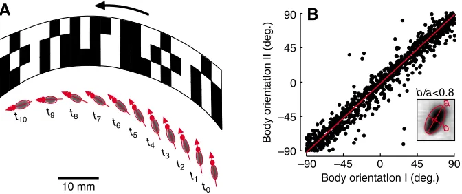
While the animal’s horizontal and vertical velocities may easily be derived from the blob’s x- and y-positions, estimations of instantaneous turning velocity may vary according to the video analysis algorithm. In 52% of all data we were able to reliably retrieve the fly’s yaw orientation from a single video frame, because in these cases the ratio between the lateral (b) and longitudinal (a) extension of the blob ellipse was smaller than 0.8 (Fig. 2B). Blob analysis permits estimation of body orientation (gaze) independent from flight direction as shown in Fig. 2A. In this example,
Drosophilafollows the rotating pattern by sliding sideways in an attempt to reduce retinal slip. Sideward translational motion without yaw rotation may reduce retinal slip in the frontal visual area of the animal, whereas the lateral eye regions experience retinal slip due to image expansion or contraction. However, since blob shape is susceptible to changes in body posture, we estimated body orientation, gaze and turning velocity from the changes in flight direction (heading) given by two (orientation, gaze) and three (angular velocity) successive data points (centre of blob) throughout our study, and in accordance with previous studies on free flight (Tammero and Dickinson, 2002b) (Fig. 1D,E). A direct comparison between the two methods exhibited a mean correlation coefficient
squared (R2) of approximately 0.62±0.12 and a mean slope of 0.99±0.02 (reduced major axis linear regression fit; mean
P=0.00015, six arena velocities, 131 flight sequences, Fig. 2B). We found small variations in R2 values among the six
tested arena velocities, suggesting that side-slip manoeuvres are apparently most frequent at maximum flight speeds in response to 900° s–1arena velocity (0° s–1:
0.99, 0.64; 100° s–1: 1.01, 0.65; 300° s–1: 0.98, 0.68; 500° s–1: 0.98, 0.78; 700° s–1:
0.95, 0.57; 900° s–1: 0.98, 0.43; for arena velocity: model II slope, R2 value). On
average, the two methods produced similar results (Student’s t-test, P>0.05, 131 flight sequences).
Nevertheless, despite the strong coincidence between the two estimates for body orientation, the fly’s actual gaze may still differ from these values due to head movements during flight (Hateren and Schilstra, 1999; Hengstenberg, 1988; Hengstenberg, 1991; Hengstenberg and Sandeman, 1986; Kern et al., 2005). A recent study on head motion in freely flying blow flies during straight flight, for example, yielded saccadic head movements at angular velocities in the range of ±100° s–1
(Hateren and Schilstra, 1999). Due to the limited resolution of the high-speed video camera, we could not address this issue in the present study.
The curvature of the animal’s flight path inside the arena, C, is equal to the inverse of path radius, r, and equal to the ratio between angular and horizontal velocity of the fly in the horizontal x/y
coordinate system and can be written as:
in which dαis the angular change in flight direction and tis time (Fig. 1E).
Flight altitude
Despite the use of a single video camera, blob analysis also allowed us to estimate the height of the flying fly inside the arena. The pictograms in Fig. 1B show that with increasing flight altitude the oval fly blob becomes increasingly circular and also larger on the video image due to a decrease in image focus. We estimated the absolute height of the animal by comparing blob size with previous measurements in which we had moved a tethered fly by hand up and down in the middle of the arena (linear regression fit,
y=75+0.84x, R2=0.94, P<0.0001, N=14 measurements, Fig. 1B). Since perspective distortion produced by the camera lens (50 mm, Nikon, AF Nikkor, Düsseldorf, Germany) was negligibly small, amounting to less than one image pixel difference between the centre and the wall of the inner cylinder, we did not expect a significant change in blob size with increasing distance from the arena centre. Thus, the altitude estimates for a fly flying in the centre and the periphery of the arena should be widely identical. We confirmed this hypothesis by experiments in which we mapped the geometry of a calibration grid displayed at the arena bottom on the recorded
C= dα (1)
dt
d2x+d2y dt
⎛ ⎝
⎜ ⎞
⎠ ⎟
−1 ,
10 mm t0
t10
t1
t2
t3
t4
t5
t6
t7
t8
t9
Body orient
a
tIon II (deg.)
–90 –45 0 45 90
–90 –45 0 45
90
B
Body orientatIon I (deg.)
A
a
b
[image:4.612.50.386.68.209.2]b/a<0.8
Fig. 2. Side-slip manoeuvre of Drosophila and body orientation. (A) Sequence of video images showing a side-slip manoeuvre of a flying fruit fly in front of the rotating pattern. The red arrow indicates body orientation that is derived from the length and width ratio of the fly’s image (grey blob). The small red dot indicates the position of the fly’s head. Sampling rate, 62.5 Hz; rotational speed of environment, 180° s–1. (B) Data of a single fly showing the relationship between body orientation derived from blob
analysis (x-scale, orientation I, b/a ratio <0.8, where b is the lateral and a the longitudinal extension of the blob ellipsis, inset) and body orientation reconstructed from the position of the fly on two successive video frames (y-scale, orientation II). In the experiment, the fly responded to an optomotor pattern rotating at 500° s–1. Flight time was 7.54 s. Linear regression fit (reduced major axis, model II
regression, y=0.995x–2.12, R2=0.94, N=775 sample points, P<0.001, red) shows a high degree of
video image. To remove data noise produced by local changes in brightness due to the rotating pattern cylinder and alteration of the fly’s body posture such as body swings during flight saccades, we applied a digital low-pass filter with a cut-off frequency of 12.5 Hz on the vertical z-coordinate.
We also used flight altitude to correct our x/y position estimates in order to obtain exact velocity estimates for the animal. Without this correction, for example, we would record an approximately 18.5% larger horizontal velocity for a fly flying at 150 mm flight altitude, and thus closer to the camera lens, than for an animal flying with the same speed but close to the arena bottom. The accuracy of this approach, however, depends on the robustness of our blob estimates that may potentially change due to image blur. Severe image blur of a fast cruising fly produces potentially larger blobs that would cause an overestimation of flight altitude. We considered this problem as follows. In our video image, each millimetre of the arena is represented on average by 6.1 video pixels. An animal that moves with an elevated forward velocity of 0.6 m s–1and close to the arena bottom would thus move 2.4 pixels within a single video frame (exposure time 4 ms). At an average blob size between approximately 100 and 200 video pixels (Fig. 1B), however, an additional 2.4 pixel offset would increase blob size by only 1.2% (200 pixels) and 2.4% (100 pixels). These values correspond to a potential error in flight altitude estimation of 1.2 and 2.4 mm, which is less than one wing length in Drosophila(2.5 mm, Fig. 1B). Even more extreme forward velocities of 1.0 m s–1would produce errors well below the measured behavioural effects. Consequently, the analysis above suggests that motion blur may not considerably change our position estimates in the vertical due to short image exposure time.
Modelling visual motion detection
A major goal of this study was to examine optomotor behaviour in freely flying Drosophila. We thus estimated the response of the fly’s
visual motion system during flight by modelling the output of the Hassenstein–Reichardt EMD for horizontal motion on both complex eyes, assuming a 360° horizontal by 80° vertical field of view. This was achieved by projecting the visual environment of the pattern cylinder on the fly’s spherical complex eyes at each moment of time according to the position and orientation of the animal inside the visual panorama. Due to the limits of our experimental setup, however, we simplified this approach as follows. First, the spatial resolution of the video image did not permit recording of the position of the fly’s head and concomitant estimation of the orientation of the eyes with respect to the visual environment, as mentioned above (Kern et al., 2005). We circumvented this restriction by determining gaze from the direction in which the fly was heading. Second, we ignored roll ‘banking’ moments around the longitudinal body axis of the animal, because these movements could not be measured from the video images. The modelled EMD output thus solely depended on changes in the angular position around the fly’s vertical axis, horizontal velocity and the distance to the surrounding panorama.
We simulated the azimuth response of the two-dimensional EMD detector system according to conventional assumptions as described previously (Borst and Egelhaaf, 1989; Borst and Egelhaaf, 1990; Tammero and Dickinson, 2002b). The spherical projection of the pattern was mapped onto the eye with a spatial resolution of 0.1° and subsequently smoothed with a Gaussian filter. The width of the Gaussian filter at 50% half-peak height was 3.8°, and its total effective range was limited to 7.6°, centred on each data point. The value of 3.8° is slightly higher than the width of angular sensitivity of each photoreceptor in Drosophila, which is approximately 3.5° (Götz, 1964), for the following reason. In the fruit fly, the angular spacing of the visual axes between two adjacent ommatidia is 4.6°. During simulation, however, we divided the 360° horizontal field of view into four units (I–IV) each (45° visual field in the horizontal) with 5° spacing.
A
B
C
D
E
F
0 Relative frequency (1) 0.12
0° s–1 100° s–1 300° s–1
[image:5.612.45.318.69.366.2]500° s–1 700° s–1 900° s–1
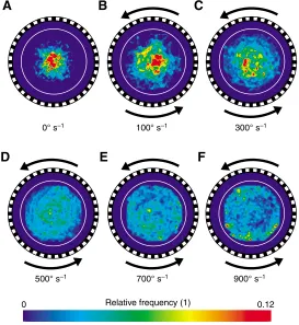
Fig. 3. Mean position probability of freely flying fruit flies at various rotational velocities of the flight arena (bin width, 4 mm⫻4 mm). (A) Stationary pattern.
(B) 100, (C) 300, (D) 500, (E) 700 and (F) 900° s–1arena velocity.
To maintain the ratio of 0.76 between the spacing of visual axes (4.6°) and the angular sensitivity (3.5°) in the analytical model, we slightly raised the width of the Gaussian filter to 3.8°. We calculated the response of the EMDs by convolving the Gaussian-filtered signal with the impulse response of a first-order high-pass and low-pass filter with a time constant of 50 ms (Kern and Egelhaaf, 2000) and 40 ms (Borst and Egelhaaf, 1989) and for a time period of 150 and 120 ms, respectively. In a separate pathway, the Gaussian-filtered signal was attenuated by a factor of 0.15, and bypassed the high-pass filter response during peripheral filtering (see Appendix). Subsequently, the signals of adjacent EMDs were spatially integrated within each 45° horizontal section and averaged within an 80° range in the vertical direction (40° below and above the horizontal) that was considered to be approximately similar to the expected spatial integration process of neural activity in the fly’s large field neurons of the lobula plate (Haag et al., 1992). In our analytical framework, all eight EMD units of the two simulated eyes produced a positive EMD output in response to front-to-back visual motion. With these outputs, we simulated two system configurations: a rotation- and an expansion-sensitive system with a lateral focus of expansion by summing up the responses of all units for one eye or by taking the difference between the sums of the two frontal (I+II) and two caudal units (III+IV) of each compound eye, respectively. See Appendix for a more detailed explanation of the equations used in the simulation.
RESULTS
Probability distributions and distance
While flying inside the optomotor free-flight arena, the flies reliably responded to the rotating visual panorama by systematically altering (i) their positions inside the arena (Fig. 3A–F and Fig. 4), (ii) their horizontal, vertical and turning velocities (Fig. 5) and (iii) their flight style (Figs 6 and 7, and supplementary material Figs S1 and S2). The probability plots in Fig. 3 show the temporal probability and thus the time the flies spent in a certain region of the arena. At stationary pattern (Fig. 3A) and low arena velocities (100–300° s–1, Fig. 3B,C), the flies apparently did not explore the entire arena space but rather spent most of their time flying near the arena centre. By contrast, at the maximum arena velocity of 900° s–1, we measured
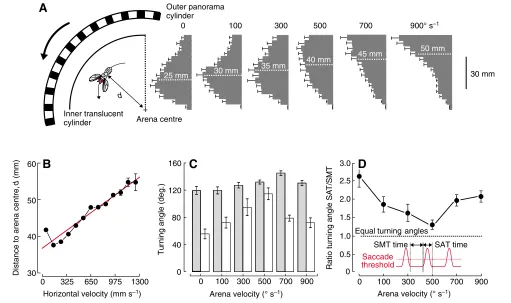
highest probabilities near the wall of the inner translucent cylinder (Fig. 3F). To analyse these changes in greater detail, we re-plotted the underlying data distributions as histograms and as a function of the distance (d) between the arena centre and the inner arena cylinder (Fig. 4A). The data show that in a stationary environment the flies cruise at a distance of 25 mm, on average (median, white dotted line, Fig. 4A). With increasing arena velocity the peak of the histograms moves towards the inner cylinder wall yielding medians ranging from 30 mm at 200° s–1to 50 mm at 900° s–1arena velocity, respectively. This result in conjunction with the geometry of the flight path suggests that fruit flies obviously prefer to move on distinct, differently sized concentric trajectories around the arena
0 100 300 500 700 900
0 40 80 120 160
T
u
rnin
g
a
ngle
(deg.)
Arenavelocity (° s–1)
0 0.5 1.0 1.5 2.0 2.5 3.0
0 100 300 500 700 900
Arenavelocity (° s–1)
R
a
tio
t
u
rning
a
ng
le
S
AT
/
S
MT
C
D
A
+
Outer panorama cylinder
Inner translucent
cylinder Arenacentre
0 100 300 500 700 900° s–1
30 mm
Horizontal velocity (mm s–1)
Di
s
t
a
nce
to
a
ren
a
centre,
(mm)
d
0 325 650 975 1300
30 40 50 60
25 mm 30 mm
35 mm 40 mm
45 mm 50 mm
SAT time Saccade
threshold
Equal turningangles d
B
[image:6.612.52.563.68.371.2]SMT time
Fig. 4. Distance between the animal and the arena centre, and turning angles at various experimental conditions. (A) Probability histograms and medians (dotted white lines) of the distributions obtained for flies responding to six different arena velocities. Means ± s.e.m. (B) Mean distance of the flying animal from the arena centre plotted against the fly’s horizontal (forward) velocity (bin width, 0.1 m s–1). Linear regression fit is plotted in red (y=0.016x+35.8,
R2=0.88, N=13 horizontal velocity bins, P<0.001). (C) Total turning angle within a flight saccade (grey) and between two saccades (open) shown as a
function of arena velocity. (D) Ratio of total turning angle during saccadic flight style and smooth turning between two subsequent saccades. Data show a minimum contribution of saccades to turning angle at 500° s–1arena velocity. SMT, time between two flight saccades; SAT, duration of a saccade. Means ±
centre. The distance of these trajectories from the arena centre significantly increases with both increasing arena velocity (linear regression fit, y=0.02x+32, R2=0.97, P<0.001, N=6 data points) and increasing forward velocity (linear regression fit, y=0.02x+38.8,
R2=0.88, P<0.001, N=13 data points, Fig. 4B). Horizontal, vertical and turning velocities
Horizontal and turning velocity in an insect that achieves optomotor equilibrium in a rotating visual environment depend on two factors: the distance of the animal from the arena centre and the angular velocity of the visual panorama. Potentially, the animal may limit horizontal speed independently of arena velocity by flying closer to the arena centre. The data in Fig. 3A–F and Fig. 4A, however, show a systematic increase in distance between the flies and the arena centre with both increasing arena velocity and increasing horizontal velocity. Thus, horizontal velocity of the animals increases from approximately 0.26±0.08 m s–1 in a stationary environment to a maximum of 0.5±0.09 m s–1 at 700° s–1 arena
velocity (Fig. 5, black circles). Maximum forward velocity apparently saturates at this level, suggesting that the fly has either reached its maximum locomotor capacity or is constrained by the walls of the inner cylinder as suggested by the asymmetrical distribution of the histograms at 500–900° s–1 arena velocity (Fig. 4A). A mean distance between the fly and the cylinder of 20–30 mm corresponds to approximately 10 wing lengths.
At the level of mean angular velocity, Drosophila widely compensates for the rotational stimulus by exactly matching turning to arena velocity. This behaviour is maintained for arena velocities ranging from 100 to 500° s–1and indicated by small and less than ±6° s–1differences between the fly’s turning rate and the blue line
that indicates the required turning rate for optomotor equilibrium (Fig. 5, blue). In general, this result is not opposite to the assumption that retinal slip drives optomotor responses, because the mean values ignore the temporal substructure of the data set. We show later in
this paper that the fly slightly oscillates its turning velocity and that the elementary motion detector system thus produces sensory feedback for flight control, even though the mean retinal slip on each compound eye is close to zero. The fly may achieve zero retinal slip on both compound eyes flying at any point of the arena, regardless of its distance to the centre: the only prerequisite is that turning velocity matches arena velocity and the fly’s horizontal velocity is equal to the translational velocity of the arena at this location. Under these conditions, the fly would be virtually tethered inside the arena while rotating together with the pattern drum. At an arena velocity above 500° s–1, turning velocity decreases with increasing arena velocity, producing a mismatch between turning rate and angular velocity of the arena of approximately –154° s–1at 700° s–1arena velocity and –617° s–1at 900° s–1arena velocity.
In the flying insect, total flight force is the vector sum of three translational forces: upward force, thrust and side slip. Depending on body mass (in the case of upward force) and the friction between the surrounding air and the moving body including the flapping wings, these forces determine the animal’s upward, forward and sideward velocities. Side slip seems to be negligible under our experimental conditions (see Materials and methods), but vertical velocity distinctly varies, depending on stimulus strength and the fly’s own horizontal velocity. The dynamics of vertical flight velocity can be characterized by two major components: an initial steep gain in flight altitude immediately after take-off
lasting approximately 0.4 s (linear regression fit, mean
slope=0.66±0.02 m s–1, N=6 sequences), followed by a more moderate increase in vertical velocity that depends on stimulus conditions (linear regression fit, model I slopes at 0° s–1 arena velocity: 0.26 m s–1; 100 s–1arena velocity: 0.20 m s–1; 300 s–1arena
velocity: 0.20 m s–1; 500 s–1arena velocity: 0.23 m s–1; 700° s–1arena velocity: 0.47 m s–1). We calculated maximum vertical flight
performance of the fly as the mean of all data points within a recording that fell within the top 1% of velocities in each distribution. These data differ only slightly between the six stimulus conditions and range from approximately 0.38±0.05 m s–1 (N=101 sample
points) measured at 500° s–1 arena velocity to approximately 0.48±0.02 m s–1(N=37 sample points) during flight in a stationary
visual environment. Mean climbing velocities of an entire flight sequence are shown in Fig. 5 (red). These data suggest only moderate vertical velocities compared with horizontal velocity ranging from values close to zero [3.7(±40.5)⫻10–3m s–1, 700° s–1]
to a small maximum value of 69.2(±69.1)⫻10–3m s–1at 100° s–1 arena velocity (N=131 animals).
Saccades and turning angles
As reported previously, fruit flies exhibit stereotypical flight saccades when flying inside a stationary environment (Tammero and Dickinson, 2002b). We distinguished saccadic turning from other forms of turning, employing a minimum threshold for peak angular velocity inside the saccade of 1000° s–1. Fig. 6A–C shows flight trajectories from three flies flying inside the flight arena with a stationary random-dot environment, all exhibiting saccadic turning at a mean horizontal velocity of approximately 0.26 m s–1(colour
coded). Although turning velocity prior to and after the saccades changes with changing arena velocity (base line of colour plots in Fig. 6D), we measured approximately the same maximum turning velocity (0° s–1arena velocity, 1542° s–1turning velocity; 100° s–1
arena velocity, 1521° s–1turning velocity; 300° s–1arena velocity, 1470° s–1turning velocity; 500° s–1arena velocity, 1477° s–1turning
velocity; 700° s–1 arena velocity, 1520° s–1 turning velocity; and 900° s–1 arena velocity, 1650° s–1 turning velocity) and saccadic
V
elocity (m
s
–1
)
0 225 450 675 900
0.2 0.3 0.4 0.5 0.6
Arena velocity (° s–1)
T
u
rning v
elocity (°
s
–1
)
0 0.1
Turning Horizontal
Vertical
–200 200 400 600 800
[image:7.612.49.262.69.252.2]0 1000 Slope=1
Fig. 5. Mean flight velocities at various rotational velocities of the flight arena. Mean horizontal (black, left scale), turning (blue, right scale) and vertical (red, left scale) velocity of the animals in response to the changes in stimulus conditions. The fly may fully achieve retinal slip compensation (grey area) when angular velocity, which is the rate of change in gaze, is equal to the angular speed of the rotating environment at a given horizontal velocity (slope=1, dotted blue). Positive turning and vertical values mean counter-clockwise turns and climbing flight, respectively; N=22 (0° s–1), 23
(100° s–1), 20 (300° s–1), 20 (500° s–1), 21 (700° s–1) and 26 flies (900° s–1).
length of approximately 130 ms under all experimental conditions (Fig. 6D). As a consequence, angular accelerations during turning are highest when the animal flies sufficiently straight before initiating the saccade (Fig. 6; 0° s–1arena velocity, black; 100° s–1 arena velocity, red). We also found a distinct increase in forward velocity between 0.06 and 0.25 m s–1(0.124±0.076 m s–1, mean ± s.d., N=6 traces, Fig. 6E) starting approximately 140 ms prior to the saccade. These data suggest that the flies first begin to turn when they achieve peak velocity during horizontal acceleration, i.e. approximately 70–80 ms or 15 stroke cycles prior to the turn. We evaluate this increase in horizontal velocity prior to turning as a potential artefact of the small flight arena later in the Discussion. During angular acceleration, horizontal velocity transiently decreases by approximately 0.12±0.007 m s–1(0° s–1arena velocity, 0.12 m s–1 forward velocity; 100° s–1arena velocity, 0.11 m s–1forward velocity;
300° s–1arena velocity, 0.11 m s–1forward velocity; 500° s–1arena velocity, 0.13 m s–1 forward velocity; 700° s–1 arena velocity,
0.13 m s–1forward velocity; and 900° s–1arena velocity, 0.13 m s–1 forward velocity) while mean saccade frequency slightly increases by 23%, from approximately 2.7 to 3.5 Hz, with increasing mean horizontal velocity measured between two saccades (intersaccade
velocity, linear regression fit, y=0.13x+2.6, R2=0.04, P=0.024, N=131 flies, Fig. 6F).
Fig. 4C shows that in our 140 mm diameter optomotor free-flight arena, the fly’s mean turning angle in a stationary environment amounted to 120±26° (N=131 flies), which is higher than the 90° reported previously. With the increasing need to turn faster in response to the angular velocity of the optomotor stimulus, saccadic turning angle increases to a mean maximum value of 145±15°, which was obtained at 700° s–1arena velocity. However, Fig. 4C also shows
that most of the increase in total turning velocity is due to an increase in smooth turning manoeuvres with turning rates below 1000° s–1
(for flight path see Fig. 7F) and not predominantly to an increase in saccadic turning angle. We found that the turning angle of smooth turns steeply increases from 56±32° at 0° s–1 arena velocity to 115±38° at 500° s–1arena velocity. At flight conditions (700–900° s–1
arena velocity) in which the animal may not stabilize its gaze as required for retinal slip compensation (Fig. 5, blue), however, smooth turning angle decreases again towards a value obtained at low arena velocity (100° s–1, Fig. 4C). This change in ratio between
saccadic and smooth turning angles is shown in Fig. 4D, assuming a mean saccadic length of 100 ms duration. Smooth turning time,
Start
Start
Start
Stop
Stop Stop
30 mm
A
B
C
0.01 0.60
Horizontal velocity (m s–1)
0.15 0.30 0.45
D
E
–0.4 0 0.4 0.8 1.2 1.6 2.0
T
u
rning velocity (10
3°
s
–1
)
0 0.1 0.2 0.3 0.4 0.5 0.6
Horizont
a
l velocity (m
s
–1
)
0 0.2 0.4 0.6 0.8
0 1 2 3 4 5 6
Intersaccade velocity (m s–1)
Sa
cc
a
de fre
qu
ency (
s
–1
)
F
30 mm 30 mm
dt =130 ms
Saccadic turning time
–0.3 –0.2 –0.1 0 0.1 0.2 0.3 Time (s)
dt =77 ms
–0.3 –0.2 –0.1 0 0.1 0.2 0.3 Time (s)
+
+
[image:8.612.52.564.68.386.2]+
Fig. 6. Saccadic flight style of Drosophila flying freely in a non-rotating random-dot arena. (A–C) Three flight paths of single fruit flies voluntarily starting from rest (top view). Flight is characterized by sequences of straight flight interspaced by 130 ms short, approximately 90–180° saccadic turns. Horizontal forward velocity is plotted in pseudo-colour. Red cross, arena centre. (D) Angular velocity during flight saccades elicited at various forward velocities in response to optomotor stimulation. Each data point of a curve represents the averaged value derived from the mean saccadic velocity of each of the 131 tested fruit flies. The mean standard deviations over all data points of each curve amount to 546 (black), 425 (red), 347 (green), 263 (blue), 287 (cyan) and 513° s–1
(purple). (E) Modulation in horizontal velocity during flight saccades. The standard deviations averaged over all data points of a curve amount to 0.12 (black), 0.12 (red), 0.15 (green), 0.10 (blue), 0.13 (cyan) and 0.17 m s–1(purple). (F) Frequency of saccades slightly increases with increasing horizontal
velocity estimated from flight sequences between saccades (intersaccade velocity). The black line represents the linear regression fit on the data set (y=1.31x+2.55, R2=0.04, N=131 saccades, P=0.024). Colour coding in D–F: 0°s–1, 0.26±0.08 m s–1, 22 (black); 100°s–1, 0.27±0.08 m s–1, 23 (red); 300°s–1,
0.33±0.07 m s–1, 20 (green); 500°s–1, 0.45±0.06 m s–1, 20 (blue); 700°s–1, 0.49±0.09 m s–1, 21 (cyan); and 900°s–1, 0.45±0.09 m s–1, 26 (purple); for arena
the time between two saccades, decreases significantly with increasing arena velocity by –21(±5.6)⫻103 s2 deg.–1 (linear regression fit, y=–0.02x+0.39, R2=0.77, P=0.02, N=6 data points)
yielding times of 0.36±0.14 s (0° s–1 arena velocity), 0.35±0.08 s (100° s–1 arena velocity), 0.33±0.13 s (300° s–1 arena velocity),
0.33±0.07 s (500° s–1 arena velocity), 0.25±0.04 s (700° s–1 arena velocity) and 0.27±0.0.07 s (900° s–1arena velocity).
EMD response during optomotor stimulation
As already mentioned, Fig. 5 suggests that the fruit flies try to match their turning speed to the angular velocity of the rotating arena in an attempt to reduce the difference in retinal slip on both compound eyes. Direct evidence for the assumption that Drosophila tries to achieve retinal slip compensation in free flight similar to the response measured in tethered flies, however, requires simulation of the optic
A
F
2.0
1.0
0
–1.0
–2.0
3.0 cm EMD o 3.0 cm
u
tp
u
t (left–right eye)
–1.5 0 1.5
EMD re
s
pon
s
e
EMD
L–R
re
s
pon
s
e
EMD
L+R
re
s
pon
s
e
C
D
EMD right eye
EMD left eye
–2.0 –1.0 0 1.0 2.0
E
0 0.55 1.10 1.65 2.2
–5.0 –2.5 0 2.5 5.0
H
I
0 0.5 1.0
J
0 0.55 1.10 1.65 2.2
T
u
rning velocity (10
3°
s
–1
)
Horizont
a
l velocity
(m
s
–1
)
+
+
Flight time (s)
t0 t1
–2.0 –1.0 0 1.0 2.0 0 180 360
G
a
ze (deg.)
0 180 360
Po
s
ition (deg.)
t0 t1
B
G
t0 t1
–1.5 0 1.5
EMD re
s
pon
s
e
t0 t1
Stationary Rotating
[image:9.612.53.561.69.559.2]Saccadic level
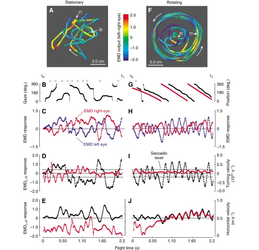
Fig. 7. Gaze and response of a rotation-sensitive elementary motion detector (EMD) system for two single flies flying in a stationary random-dot environment (A–E) and under optomotor stimulation due to the rotating arena (500° s–1counter-clockwise rotation, F–J). The time traces in B–E and G–J are subsets of
flow during flight. We thus simulated a Hassenstein–Reichardt EMD array for horizontal motion as described above. Typical time traces for (i) the EMD response of a rotation-sensitive system simulated for both compound eyes in free flight, (ii) the fly’s gaze towards the pattern and (iii) its body motion are shown in Fig. 7 for two different experimental conditions: flight in a stationary environment (Fig. 7A–E, Fig. 8) and flight with an outer panorama rotating counter-clockwise at 500° s–1(Fig. 7F–J).
Despite the smaller arena size compared with previous research (Tammero and Dickinson, 2002b), the data superficially show the same typical properties of flight behaviour, such as regular saccades. In the stationary environment the simulated EMD response is approximately similar in magnitude for the two eyes, because the flies typically remained close to the arena centre (Fig. 7A, red cross). Fig. 7D,E shows the relationship between turning and left-minus-right eye EMD response, and between horizontal velocity and left-plus-right eye EMD output. The difference in EMD response is also plotted in pseudo-colour for each sample point of the flight paths in Fig. 7A,F. A common feature of all flight sequences and at all stimulus conditions is that turning and horizontal velocities typically change out of phase, often producing regular large oscillations of the rotation-sensitive EMD array (left-minus-right eye). These oscillations are shown in Fig. 7I during optomotor stimulation with a rotating pattern cylinder at 500° s–1. In this example, the fly stabilizes its gaze (black) towards the pattern (red), since the two curves in Fig. 7G run in parallel, while flight saccades are almost absent (grey dots). To further assess the mean response of the rotation-sensitive EMD detector system under the various stimulus conditions, we plotted the EMD outputs as normalized histograms for both left-minus-right (Fig. 9A) and left-plus-right eye (Fig. 9B). We derived the histogram peak and the width of the distribution by fitting Gaussian curves (Fig. 9, red) and plotted both measurements as a function of arena velocity in Fig. 10B (left-minus-right eye) and Fig. 10C (left-plus-right eye). The data show that in a stationary environment, the difference in EMD output of the two eyes is close to zero. This finding suggests that there is no preferred direction of turning behaviour and/or the time ratio between turning and straight flight is relatively small. During optomotor stimulation, the flies apparently minimize both the difference and the sum in retinal velocity between the two eyes because the EMD responses of the rotation-sensitive array remain close to zero over a wide range of arena velocities (linear regression fit, y=–0.12+1.16⫻10–4x, R2=0.05,
P=0.66, N=6 data points, Fig. 10B; y=–0.12+1.44⫻10–4x, R2=0.30, P=0.26, N=6 data points, Fig. 10C, respectively).
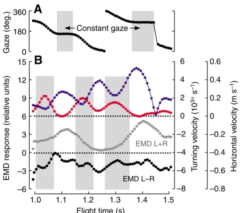
1.0 1.1 1.2 1.3 1.4
–6 –3 0 3 6 9 12 15
–8 –6 –4 –2 0 2 4 6
–0.8 –0.6 –0.4 –0.2 0 0.2 0.4 0.6
Flight time (s)
1.5
EMD re
s
pon
s
e (rel
a
tiv
e
u
nit
s
)
EMD L+R
EMD L–R
0 180 360
G
a
z
e (deg.)
Constant gaze
A
B
T
u
rning v
elocity (10
3°
s
–1
)
Hor
iz
ont
a
l v
elocity (m
s
[image:10.612.51.292.67.280.2]–1)
Fig. 8. Close-up of the flight sequence in a stationary arena cylinder (left turn). (A) The fly’s gaze calculated from body orientation. (B) Inverse relationship between horizontal (blue, right scale) and turning (red, right scale) velocity, and output of a rotation-sensitive EMD system (left-minus-right eye, black, left scale).The sum of EMD responses of the two eyes is plotted in grey (left scale). Light grey area indicates times at which the fly exhibits approximately constant gaze in A and saccades in B.
Rel
a
tiv
e EMD
u
nit
s
Rel
a
tiv
e EMD
u
nit
s
A
–
+ Left-minus-right eye
Left-plus-right eye
B
0 2.5
–2.5 Normalized
counts 0 2.5
–2.5
0 100 300 500 700 900° s–1
[image:10.612.48.549.502.697.2]Expansion-sensitive EMD system
Due to the previous finding that steering in response to image rotation might emerge from a visual system organized to detect expanding flow fields rather than a rotation-sensitive system (see Introduction), we also simulated the EMD response of an expansion-sensitive system (Fig. 10A, lower pictogram). The left-minus-right eye difference of this detector system is plotted in Fig.·10D and suggests that this detector consistently produces a mean response close to zero and without a significant slope (linear regression fit,
y=7.40⫻10–3–2.4⫻10–6x, R2=0.01, P=0.85, N=6 data points,
Fig. 10D). To highlight the relationship between turning velocity and the two different types of EMD system, we plotted the EMD response for two flies flying in a stationary environment and under optomotor stimulation (300° s–1) in Fig. 10E and F, respectively. The
linear regression analysis fit suggests that in these animals the output of the rotation-sensitive system (black) significantly decreases with increasing turning velocity by a slope of –2.8⫻10–3deg.–1s in a stationary environment (P<0.0001, R2=0.44, N=319 sample points)
and by –4.0⫻10–3deg.–1s at 300° s–1 arena velocity (P<0.0001,
R2=0.55, N=794). In contrast, the left-minus-right eye response of
the expansion-sensitive system (red) exhibits much smaller regression coefficients (R2values) of 0.19 (0° s–1) and 0.01 (300° s–1
arena velocity), and without a significant slope during optomotor stimulation (P>0.05, R2=0.01, N=794). Mean regression statistics
for the six arena velocities and all 131 flies is shown in Table 1. In general, the rotation-sensitive EMD system produced significant
slopes in most of the experimental conditions (100–700° s–1arena velocity), whereas none of the slopes calculated for the expansion-sensitive system were significantly different from zero (0–900° s–1 arena velocity).
Velocity and curvature of flight path
The relationship between arena velocity and horizontal/turning velocity suggests that the curvature of the flight path might be constrained by at least two factors: first, the fly’s locomotor performance and/or, second, the relatively small size of our flight arena. Both hypotheses are driven by the results in Fig. 11, which show how path curvature depends on horizontal (Fig. 11A) and turning velocity (Fig. 11B). In this figure we have plotted the relative frequency of all tested flies in pseudo-colour to highlight the most frequent locomotor states and the boundaries of the data distributions. Due to the counter-clockwise rotation of the visual panorama, most data points are scattered around positive curvatures as indicated in red. Moreover, the data show a decrease in variance of path curvature with increasing horizontal velocity (Fig. 11A). At maximum flight velocities of approximately 1.04 m s–1for single
flies, curvature is constrained to a single value of approximately 0.015 mm–1or a path radius of 67 mm, which is close to the arena
radius of 70 mm. This result suggests that at maximum horizontal velocity, turning behaviour might be limited by the radius of our optomotor arena because Fig. 3 and Fig. 4B show that under these conditions the flies commonly remain near the cylinder walls. By
0 0.2 0.4 0.6 0.8 1.0
–5.0 –2.5 0 2.5 5.0
0 0.2 0.4 0.8 1.0
Arena velocity (103° s–1) 0.6
B
C
0.5 height
2 s.d. 0.5 height 2 s.d.
–2 –1 0 1 2
EMD re
s
pon
s
e L–R eye
EMD re
s
pon
s
e L–R eye
EMD re
s
pon
s
e L–R eye
EMD re
s
pon
s
e L+R eye
0 0.2 0.4 0.8 1.0
Arena velocity (103° s–1) 0.6
D
0.5 height 2s.d. I
II III
IV
I
II III
IV
+
Focus of expansion Rotation-sensitive
system
Expansion-sensitive system
Rota tion-sensitive system
Expans
ion-sensitive system
EMD re
s
pon
s
e L–R eye
Rota tion-sensitive system
Expans
ion-sensitive system
–1.50 –0.75 0 0.75 1.50
Turning velocity (103° s–1) –3.0
–1.5 0 1.5 3.0
–0.5 0 0.5 1.0 1.5 2.0
–3.0 –1.5 0 1.5 3.0
F
E
I II III IV
I II III IV
A
cw ccw cw ccw
–2 –1 0 1 2
+
[image:11.612.54.561.65.352.2]+
Fig. 10. Outputs of two EMD system types in freely flying fruit flies. (A) According to previous findings on yaw torque production in tethered flies, we simulated a rotation-sensitive EMD system (upper pictogram) and an expansion-sensitive system with a lateral focus of expansion (lower pictogram). (B,C) Relative mean EMD output of the rotation system estimated from the Gaussian fit to the histograms shown in Fig. 9A and B, respectively. Errors represent the standard deviation of the fit, which is 0.5 the width of the Gaussian curve at half-peak height. Data in B and C show the mean difference (left-minus-right eye) and sum (left-plus-right eye) of the EMD response between the two eyes, respectively. (D) Relative mean EMD output (left-(left-minus-right eye) of an expansion-sensitive system estimated from Gaussian fits similar to those shown in Fig. 9A,B. (E,F) EMD response of the rotation (black)- and expansion (red)-sensitive EMD system in flight sequences derived from two flies flying in a stationary environment in E and during 300° s–1arena velocity in
contrast, flight curvature may vary distinctly by approximately ±0.2 mm–1 at low horizontal velocities around 0.04 m s–1. For comparison, the relationship between angular velocity and path curvature is shown in Fig. 11B in which positive (negative) values indicate left (right) flight turns.
The relative frequency of the various combinations between horizontal and turning velocity during Drosophilaflight is shown in Fig. 11C. Due to both the saturation value for horizontal velocities at approximately 0.49 m s–1and the apparent break point in turning
velocity at 500° s–1, both shown in Fig. 5, we split the data set into a lower and higher velocity subset (vertical line, Fig. 11C). This splitting appears to be justified by the apparent change in slope at the break point, which we confirmed by linear regression analysis on 12 (10), 0.04 m s–1wide velocity bins derived from the left (right) half of the distribution (left-hand distribution: y=312+0.42x, R2=0.90, P<0.0001, N=12 data points; right: y=58+0.96x, R2=0.87, P<0.0001,
N=10 data points, Fig. 11C). The smaller slope (equal to mean path curvature) at high horizontal velocities suggests that the angular velocity of Drosophilais increasingly compromised with increasing forward velocity. As mentioned above, these changes might be due to size constraints of the arena that increasingly limit path radii with
decreasing distance from the cylinder wall or by the maximum locomotor capacity of the fly’s flight apparatus. The latter hypothesis is tackled in the following section.
Modelling force balance and path curvature
Velocity and thus flight direction of a flying insect depend on the ratio between vertical (upward force), horizontal (thrust) and lateral forces (side slip) multiplied by normalized friction, and on the moments around these vectors: yaw (vertical axis), roll (horizontal axis) and pitch (lateral axis, Fig. 12A). The data distribution in Fig. 11C suggests that angular velocity around the vertical axis is increasingly constrained with increasing horizontal velocity and during flight at elevated locomotor performance the two measurements are inversely correlated, producing almost 180° shifts in phase angle (Fig. 8B). To further discuss these dependencies between biomechanical measurements and measured flight behaviour, we developed a numerical model that predicts the outer boundaries of flight velocity distributions (maximum estimates) from total locomotor capacity and also allows predictions of the relationship between flight path curvature, turning and the animal’s horizontal velocity. Although the analytical model makes some
P
a
th c
u
rv
a
t
u
re (mm
–1
)
–0.2 –0.1 0 0.1 0.2
–2 0 2
–2 –1 0 1 2
Horizontal velocity (mm s–1) Turning velocity (103° s–1)
0 Relative frequency (1) 0.12
A
B
C
0 275 550 825 1100
Horizontal velocity (mm s–1)
0 275 550 825 1100
–1 1
T
u
rning v
elocity (10
3°
s
–1
[image:12.612.45.568.90.233.2])
Fig. 11. Relationships between flight path curvature, horizontal and turning velocity in freely flying fruit flies. (A) The variance in flight path curvature decreases with increasing horizontal velocity. At maximum forward velocity of approximately 1.0 m s–1, flight path curvature is apparently constrained to a
unique value of approximately 0.016 mm–1. (B) Relationship between flight path curvature and turning velocity. (C) Data distribution between horizontal and
angular velocity. Each data point represents an 8 ms position measurement of each of the tested flies. The vertical line in C indicates maximum horizontal velocity of 0.49 m s–1averaged over all flies. Normalized relative frequencies are plotted in pseudo-colour.
Table 1. Linear regression fit statistics between the fly’s turning velocity and the left-minus-right eye output of the rotation- and expansion-sensitive elementary motion detector system, respectively
Arena velocity
(° s–1) EMD system Slope ⫻10–3 y-intercept R2 P N
0 Rotation –2.51±2.71 0.02±1.02 0.12±0.12 0.13±0.23 (NS) 22 100 Rotation –4.00±0.42 0.77±0.19 0.23±0.09 0.003±0.009** 23 300 Rotation –4.63±1.16 1.50±0.43 0.36±0.11 0.004±0.01** 20 500 Rotation –5.40±1.02 2.57±0.44 0.47±0.11 <0.0001*** 20 700 Rotation –4.38±0.72 2.68±0.45 0.34±0.12 0.03±0.14* 21 900 Rotation –1.76±2.26 1.60±1.06 0.06±0.05 0.22±0.23 (NS) 26 0 Expansion –0.21±1.08 0.10±0.33 0.07±0.10 0.34±0.29 (NS) 22 100 Expansion –0.50±1.10 0.20±0.37 0.04±0.04 0.26±0.32 (NS) 23 300 Expansion 0.64±1.42 –0.25±0.58 0.10±0.12 0.15±0.23 (NS) 20 500 Expansion 1.05±1.85 –0.51±0.94 0.06±0.07 0.18±0.29 (NS) 20 700 Expansion 0.60±1.90 –0.33±0.99 0.03±0.04 0.29±0.34 (NS) 21 900 Expansion –0.33±1.59 0.18±0.70 0.04±0.04 0.35±0.32 (NS) 26 We performed model I regression fit on a data subset ranging from 0 to 900° s–1turning velocity. *0.05, **0.01 and ***0.001 significance level of slope. NS, not
[image:12.612.55.552.525.691.2]inherent assumptions on flight mechanics, we found a marked agreement between experimental data and the data produced by the simulation.
The analytical model is based on the simple assumption that minimum curvature of a flight trajectory is constrained by the fly’s maximum locomotor capacity and thus by the limits of total aerodynamic force production. We further assume that the production of moments around the three body axes requires only negligible aerodynamic force and that total force balance can thus be reduced to the vector sum of upward force, thrust and side slip. This assumption is fostered by results obtained during object orientation behaviour of tethered flying fruit flies that modulate their yaw moments within a range of approximately ±1.0 nN m peak to peak (Heisenberg and Wolf, 1984), using graduated alterations in the bilateral difference in wing stroke amplitude (Götz, 1983). We approximated the mean length of the moment arm for yaw turning between the fly’s centre of gravity and the aerodynamic force vector to be 2.1 mm, assuming that the chord-wise aerodynamic circulation is at maximum close to a span-wise location of 65% wing length [wing length, 2.5 mm (Lehmann, 1994; Birch and Dickinson, 2001; Lehmann and Pick, 2007; Ramamurti and Sandberg, 2001)]. Consequently, the production of a yaw turning moment of 1.0 nN m would require an aerodynamic force of approximately 0.47μN, which is only approximately 3% of the flight force Drosophila
produces at maximum locomotor performance (Lehmann, 2004; Lehmann and Dickinson, 1997). The numerical model also requires that the fly produces lateral forces during turning due either to banking (roll turn) towards the inner curve side or to modification of wing kinematics without large changes in body posture, similar to those observed in hover flies (Collett 1980a; Collett, 1980b). We moreover ignored body inertia during translational acceleration and the mass moment of inertia during rotational accelerations of the animal because a recent study showed that yaw turning is dominated by drag on the wings and not body inertia (Hesselberg and Lehmann, 2007).
Total flight force Ftproduced by both wings is equal to the vector sum between vertical force Fv(upward force), horizontal force Fh
(thrust) and lateral force Fl and can be expressed as:
To replace force by velocity in the equation above, we assumed Stokes’ friction for body motion at a low Reynolds number. At a value of 1.0 mm for body width and 1.2 m s–1horizontal velocity as an upper limit in Drosophila, maximum Reynolds number amounts to approximately 80, and horizontal velocity uhmay be expressed as directly proportional to thrust according to Stokes’ law by:
Fh=kuh. (3)
In this equation kis normalized friction, i.e. the ratio between friction and velocity (unequal to frictional coefficient). Similar to this estimate, vertical force can be written as the sum of gravitational force and drag on the fly body when moving at a vertical velocity uv; that is:
Fv=kuv+ mbg, (4)
in which positive values of uvmean climbing flight, mbis the body mass of the tested flies of 1.24 mg and gis the gravitational constant. We estimated the lateral force needed to keep the animal on track during yaw turning as:
Fl=mbuh2r–1, (5)
in which ris path radius (inverse of path curvature). If we assume that side-slip velocity is negligibly small in Drosophila (see Materials and methods) and replacing the force terms in Eqn 2 by Eqns 3–5, horizontal and vertical flight velocity can be expressed by the following equations:
(6)
uh=m1 b
1
2 r
4k4−4r m b 2 F
v2−Ft2
(
)
−r22 k2
(
)
,(2)
Ft = Fh2+F v2+Fl2.
Fv
Fg r
Flight path
Ft
Fl
Fd
CoR
Fh
0 5 10 15 20 25 30
Ascending order Ft
0 0.5 1.0 1.5 2.0
0 250 500 750
–1.2 –0.7 –0.2 0.3 0.8 1.3
0 50 100 150 200
Flight path radius (mm) uh
ul
Zero climbing velocity
Flight
v
elocity (m
s
–1
)
D
Minim
u
m flight p
a
th r
a
di
us
(mm)
Horizontal velocity (m s–1) 13.1 μN
16.3μN
21.0 μN
32.4 μN
F
orce (
μ
N)
Fh
Fl
Fv
Ft
B
C
A
Fl
[image:13.612.47.363.479.747.2]uv,max
Fig. 12. Numerical model for force balance in freely flying fruit flies. (A) Forces produced by the flying insect and forces acting on the fly body during flight on a curved path. Total flight force Ftis equal to the
vector sum of horizontal (Fh), vertical (Fv) and lateral
forces (Fl). (B) Total force of each fly and the
corresponding force components within the flight recordings that fell within the top 10% maximum of total force. Data are sorted after Ftfor all 131 tested
animals. (C) Minimum flight path radius at a given forward velocity and level flight, shown for four estimates of total flight force. (D) Alterations in vertical climbing velocity when horizontal flight velocity is kept constant at 0.6 m s–1. Grey indicates
path radii at which the fly loses flight altitude while turning. The numerical model predicts that at 0.6 m s–1forward speed fruit flies may only support
their body weight when the flight path radius exceeds 50 mm (dotted line). Fg, gravitational force
(body weight); CoR, centre of radius of a flight turn; r, radius of the flight path; ul, lateral (side-slip)
velocity; uh, horizontal velocity; uv,max, maximum
and
respectively. Eventually, the fly’s turning velocity ωcan be derived from horizontal velocity and path curvature, which is given by:
=uhr–1. (8)
We adjusted normalized friction according to maximum flight force used in the simulation, for the following reason: experimental data showed that normalized friction of the Drosophila body is
(7)
uv= Ft2−kuh2−mb2uh4r−2−mbg
k ,
approximately 4⫻10–6kg s–1 (Lehmann, 1994). At straight level flight and assuming that maximum total flight force production Ft
is 13.1μN, this value predicts a maximum horizontal velocity of 1.22 m s–1at maximum thrust of approximately 4.86μN [Eqn 2 and
3 (Lehmann and Dickinson, 1997)]. A value of 1.22 m s–1
approximately matches our experimental data and is equal to the mean of all data points within the recordings that fell within the top 0.82% (0.44 s flight time) of all tested flies. However, since the estimate of normalized friction is susceptible to major errors and horizontal velocity estimates are more reliable, we found it advantageous to calculate normalized friction from Eqn 3 using a constant of 1.22 m s–1 for horizontal velocity and deriving thrust
Start
+
+
0 7 14 21 28
0 7 14 21 28
0 7 14 21 28
5 12 19 26 33
0 0.2 0.4 0.6 0.8
0 0.2 0.4 0.6 0.8 0.30 0.15 0 0.15 0.30
Start
–1.5 0 1.5 3.0
Saccade level
Flight time (s)
0 0.4 0.8 1.2 1.6 2.0 2.4 0 0.4 0.8 1.2 1.6 2.0 2.4
A
C
D
E
F
G
H
I
J
16.3μN 500° s–1 0° s–1
13.1 μN 21.0 μN
32.4 μN
Stop
Stop
B
Stationary Rotating
Ve
rt
ic
a
l v
elocity
(m
s
–1
)
Hor
iz
ont
a
l v
elocity
(m
s
–1
)
T
u