Parameters Identification of Nonlinear DC Motor
Model Using Compound Evolution Algorithms
Shuang Cong, Guodong Li, Xianyong Feng
Abstrac—The genetic algorithms (GA) with global optimization character and the simplex method are combined and used into the application of the parameter identification. The nonlinear dynamic model of an actual DC motor including the nonlinear friction torque is established. By means of the compound evolution algorithms proposed, the detail procedure of the all parameters identification in the DC motor with actual system’s input-output data are given. The effectiveness of identification is verified by the comparison between actual system values and model’s in the different situations including the motor running in the dead zone, saturated zone and linear zone, respectively.
Index Terms—genetic algorithms; simplex method; global optimization; parameters identification; nonlinear friction
I. INTRODUCTION
DC motor has been widely used in the engineering field due to its simple structure, outstanding control performance and low cost. In high accuracy servo control system, high control performance of DC motor is needed. The traditional model of DC motor is a 2-order linear one, which ignores the dead nonlinear zone of the motor. Unfortunately, the dead zone caused by the nonlinear friction would bring great effect to servo systems. Therefore, it is vital to model the dead zone of DC motor accurately in order to improve the performance of servo system. Concerning the nonlinear friction of motor, Armstrong-helouvry B. et al. [1]have already conducted thorough research and proposed a nonlinear friction model. This friction model relates to the speed and time, and the motion goes four areas from the static friction to the coulomb friction. Moreover, this friction model structure is quite complex, and 7 parameters need to be identified. In order to simplify applications and reflect the real nonlinear friction of the motor accurately, a simplified friction model was proposed by Cong S. et al. [2], which is expressed as
sgn( ) ( ) exp( ) sgn( )
f c s c
T =T ⋅ ω + T −T ⋅ − ⋅α ω ⋅ ω (1)
Where, Tcis the Coulomb friction torque (N m⋅ ); Ts is static friction torque (N m⋅ ); α is time constant; ω is the angular speed of the rotor (rad/s).
A method used to identify the nonlinear DC motor model was introduced also by Cong S. et al [3], which identified the linear part model and nonlinear friction model of DC motor, respectively. The parameters of linear part model were identified by using least square method, and the
Manuscript received Jan. 6, 2010. This work was supported in part by the National Science Foundation of China under Grant No. 60774098
S. Cong G Li and X. Feng are with Department of Automation, University of Science and Technology of China, Hefei, 230027, China. Corresponding author’s e-mail: [email protected]
parameters of nonlinear friction model were identified through experiments. Even though this method could identify all the parameters of DC motor model including the nonlinear friction, the parameters of linear part model and nonlinear friction model must be identified separately, which undoubtedly decreases the efficiency and accuracy of system identification. Due to these disadvantages, a new method which could identify the linear and nonlinear part models simultaneously is needed to increase the efficiency and accuracy of system identification.
Genetic Algorithms is a kind of stochastic search algorithm based on the rule of evolution of the biological universe, which was firstly proposed by Holland [4] in 1975. GA has the ability to search global optimal solution of the space without being trapped in local minima. There are a great amount of applications of GA in the field of nonlinear system identification, and many researchers [5-15] introduce the identification of motors or power electronics systems based on GA. Though GA has the ability to search global optimal solution of the space, the local search ability of this algorithm is poor, especially when the optimization problem is complex, and GA may take relatively long time to search the global optimal solution. In addition, nonlinear system identification is a kind of quite complex optimization problem, thus just using GA to conduct parameter identification would decrease the convergence speed and practicality of the algorithm. On the other hand, simplex method [16] has the ability to converge the optimal solution more quickly and does not need the differential information of objective function, thus this method could be used to identify nonlinear system conveniently and efficiently.
In this paper, genetic algorithms and simplex method are adopted to identify the parameters of nonlinear DC motor model. GA is applied to conduct the global search and find promising regions of the search space, and then simplex method is adopted to conduct local search based on the search result of GA. Additionally, the initial value of simplex method is the search result of GA, so this algorithm can assure that the global optimal solution is searched out efficiently. Because of the fast convergence speed of simplex method, the efficiency of parameter identification would be increased significantly. And in order to increase the accuracy of the model, the nonlinear friction torque in (1) is adopted to model the dead zone of DC motor in this paper. Some of contents of this paper have published in the [17].
simulation, the efficiency and advantages of the proposed method are validated, and the identification results are verified by using the input-output data of actual system. The conclusion of this paper is given in section 5.
II. NONLINEAR DC MOTOR MODEL
The DC motor equivalent circuit under rating excitation is as shown in Fig. 1.
2
/
-
,
/3
+
175
4
6
4
6
0
.
*.
Fig. 1 DC motor equivalent circuit
The voltage balance equation of DC motor armature circuit is expressed as
a a di e
u R i L K dt ω
= ⋅ + ⋅ + (2)
where, is armature current (A); is equivalent inductance of armature circuit (H); is equivalent resistance of armature circuit ( ); is terminal voltage of armature circuit (V);
i La
a
R
Ω u
e
K is voltage coefficient of DC motor (V s ). The torque balance equation of DC motor is expressed as
/rad ⋅
t d
K i B J dt
ω ω
⋅ − ⋅ = ⋅ (3)
where, Jis the inertia moment of the rotor (Kg m⋅ 2); Kt
is the torque coefficient of DC motor ( ). is viscous friction coefficient of DC motor ( ). The linear DC motor model is obtained by combining (2) and (3), which is shown as
N m/A⋅ B N m s/rad⋅ ⋅
t
a e a
J B K i L i K R i u
y
ω ω
ω ω
= − + ⎧⎪
⎨
= − − + ⎪⎩
=
Considering the effect of nonlinear friction, the nonlinear friction torque[2, 3], which as shown in (1), is applied to model the dead zone of DC motor. Then the nonlinear DC motor model is shown as
sgn( ) ( ) exp(- )sgn( )
t c s c
a e a
J B K i T T T L i K R i u
y
ω ω ω α ω
ω ω
⎧ = − + − − − ⋅ ⋅
⎪ ⎨
= − − + ⎪⎩
=
ω (4)
The DC motor model is transformed into 2-order nonlinear model from traditional 2-order linear one due to the presence of nonlinear friction torque, which makes the model of DC motor more accurate. In control system, the nonlinear friction moment can be eliminated by using feed-forward compensation method, which would improve
the control performance of the system. Conduct variable replacement to (4)
1 2 6 7 8
4 3 5
sgn( ) exp( )sgn( )
K K i K K K i K K i K u
y
ω ω ω ω
ω ω
⎧ = − + − − −
⎪ ⎨
= − − + ⎪⎩
=
ω (5)
where, K B J1= / ; K2=K Jt/ ; K3=R La/ a; K K L4= e a/ ;
5 1/ a
K = L ; K6=T Jc/ ; K7=(T Ts− c)/J; K8=α.
Define K =[K K K K K K K K1, 2, 3, 4, 5, 6, 7, 8] as the identified parameter vector of DC motor, which has 8 parameters need to be identified. Moreover, the positive and negative direction responses of the DC motor are asymmetrical, which means that the parameters of the motor are different, when it runs in different directions. Therefore, it is necessary to identify the positive and negative direction models of DC motor respectively in order to increase the accuracy of the model. Thus there are 16 parameters need to be identified in all.
III. IDENTIFICATION OF NONLINEAR SYSTEM BASED ON GA AND SIMPLEX METHOD The problem of nonlinear system identification can be described as
( , , )
f C
=
= +
X X θU
Y X n (6)
where, X is state vector of the system; is parameter vector to be identified; is input vector of system; is the coefficient matrix; is output vector of the system;
is the measurement noise vector. The task of identification is to identify the system parameters by using the input signal U and output signal Y of the actual system. There is no special requirement for the nonlinear system, and the nonlinear system could be MIMO system.
θ
U C
Y n
θ
1 2 [ ,θ θ θL]T = " θ
1 2
( ) [ ( ),t = u t u t( )"u tn( )]T U
1 2
( ) [ ( ),t = y t y t( )"y tm( )]T Y
where,0≤ ≤t TF, and there are N sampling points in all; is a n-dimensional vector; is a m-dimensional vector; is a L-dimensional vector.
( )t
U Y( )t
θ
In this section, GA and simplex method are adopted to identify the parameters of nonlinear system. GA performs well for a global search and is capable of quickly finding promising regions of search space. In order to improve the efficiency of parameter identification, while simplex method is applied to continue the optimization by using the search result of GA as its initial solution. The sketch map of parameter optimization is as shown in Fig. 2.
method is chosen and the initial population is generated stochastically in the optimization space. Suppose that the optimization range of variable is and the precision of the variable is
a [amin,amax]
δ , then the binary code length of variable is shown as follows: a
max min 2
Length ( ) ceil loga a a
δ
⎛ ⎛ − ⎞
= ⎜ ⎜ ⎟
⎝ ⎠
⎝
⎞ ⎟ ⎠
where, ceil( )A is defined as the nearest integers greater than or equal to A.
The global optimal point GA ""
Simplex Method The sub-optimal point
[image:3.595.88.243.185.330.2]The initial point
Fig. 2 Sketch map of parameter optimization
In order to overcome the disadvantages of roulette wheel selection strategy, the normalized geometric ranking selection strategy is adopted, which ranks the individual fitness and adopts the normalized geometric ranking function to define the selection probability as ; where, r is the rank of the individual, in which the best one is put the first place; q is the probability of selecting the best individual, which is chosen as 0.08.
1 (1 )r i
P =q′ −q −
(
1 (1 )M)
q′ =q − −q , where, M is the size of a generation. Simple crossover and binary mutation are adopted, and the crossover probability is chosen between 0.25 and 0.75 and mutation probability is chosen between 0.001 and 0.2. In this paper, the two probabilities are chosen as 0.6 and 0.1, respectively. The larger the size of population, the higher the optimization accuracy, but the program would consume much more time to search. Generally, the size of population is chosen between 50 and 150, and the size is chosen as 80 in this paper. The individual fitness function is defined as
( )
(
)
(
)
( )
( ) ( )
1
1 ˆ
ˆ , ˆ
k
i N T
k k
l
i i
l
Fitness
t ,tl ν =
=
⋅ ⋅ +
∑
gE g Η E g
where, gˆi( )k is the ith individual of the kth generation;
{
1 2diag λ λ, λm
}
= "
Η is the weight matrix; ν is a
positive constant, which ensures that the denominator of the function is not equal to 0; is the N
sampling points in the range of
1 2, , l N
t t " "t t
0≤ ≤t TF, where, t1=0 and tN =TF ;
(
ˆ( )k ,)
ˆ( ) (i t = t −
E g Y Y t) is the error function.
Simplex method is used to continue the optimization by
using the search result of GA. Firstly, the parameters should be initialized including acceptable error, contraction coefficient, expansion coefficient, initial step and initial simplex; the optimal point, the sub-worst point and the worst point are identified by using the objective function of the simplex acmes. Then judge whether the stop condition is satisfied. If not satisfied, the reflection point is computed to ascertain contraction or expansion and to construct new simplex. If the simplex could not be compressed, the simplex is shrunk to half of the original one. And the search is continually conducted.
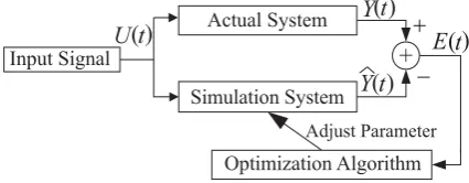
The basic components of nonlinear system identification is as shown in Fig. 3; where, is the input signal of actual system; is the output signal of actual system;
is the output signal of simulation system; ( )t
U ( )t
Y ˆ( )t
Y E( )t is the
error signal, which is used to compute the fitness function and objective function. The optimization algorithms are used to adjust the parameters of the simulation system, which makes the error signal E( )t as small as possible.
+ HD EK
I J
-;=A@075;19
,2@A190B?@4:
07:A91@7<;0B?@4:
,38A?@/1>1:4@4>
.=@7:7C1@7<;,95<>7@6:
F
G D EK
JD EK EK
[image:3.595.319.532.302.385.2]D
Fig. 3 Basic components of parameter identification
IV. IDENTIFICATION RESULTS AND VALIDATION
A. Introduction of actual system
The basic scheme of experimental equipment is as shown in Fig. 4; where, the output and input signals of micro-processor are voltage and angular speed, respectively, and both of them are digital. The voltage digital signal is converted into actual analog voltage signal through the D/A converter and servo amplifier, and this analog voltage signal is applied to the terminal of armature circuit. The actual speed signal is converted into digital signal through tacho-generator and the A/D converter, and this digital signal is read into micro-processor. In the experiments, the digital voltage and angular speed signals could be acquired. In order to identify the real parameters of DC motor, the ratio of the digital to actual voltage signal KD A/ and the ratio of digital to actual angular speed signal KA D/ should
be determined in advance.
-=4;>8 C6;>5:BD A:8=4; FLI J
G L
/:8:B4; C6;>5:BD A:8=4; ELI J
/,--,/
/. 0>B>@ 0:5@>
1@>56AA>@
/:8:B4; C>;B486
3459> +86=6@4B>@
26@C> -<?;:7:6@ A:8=4;
K K
Fig. 4 Basic scheme of experimental equipment
11 /
2 2048 85.3333 V 24V 24V
D A
K = = =
For the precision of A/D converter is also 12-digit, the range of analog signal is [ 5 , the speed measurement range of tacho-generator is from -800r/min to 800r/min, the resolution of A/D converter
is , and the output slope of
tacho-generator k is
V, 5V] −
5V/2048=0.0024V
5V
0.0597V rad/s 800 2 /60 rad/s
k
π
= =
⋅
The ratio of digital to actual speed signal KA D/ is then
/
0.0597V/rad/s
24.875 rad/s 0.0024V
A D
K = =
The nonlinear DC motor model as shown in (5) is a SISO system, which satisfies (6). Therefore, we could use the method introduced in section 3 to identify the nonlinear system model. Due to the difference between positive and negative direction responses in the DC motor, it is necessary to identify the positive and negative direction models, respectively. The data used to identify the model contain stochastic noise, and the parameter identification method introduced in section 3 does not need to filter the actual data, which undoubtedly increases the identification accuracy.
B. Determination of system parameters using GA and simplex method
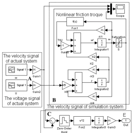
The simulation scheme of the system is as shown in Fig. 5, in which part A is the input and output data of actual system, part Bis the basic scheme of DC motor. In part B, the saturation-element is added to the simulation system in order to simulate the real situation of the system controlled. The positive and negative direction saturation speeds are 62.3rad/s and 33.5rad/s, respectively, which are obtained through system testing; part C is the basic scheme of error computation.
Using GA to identify the nonlinear system, the parameters of GA are chosen as follows:
The crossover probability ; the mutation probability ; the total generations of evolution
; the size of population ; the fitness function parameter
0.6 c
p = 0.1
m
p = max 100
K = M =80
1
ν = ; the precision δ =10−6 ; the search ranges of GA are K1∈[0, 5] , K2∈[0, 50] ,
, , ,
3 [0, 80]
K ∈ K4∈[0, 30] K5∈[0, 30] K6∈[0, 30] , , ; the fitness function is
7 [0, 20]
K ∈ K8∈[0, 0.01]
( )
(
)
21 1 ˆ
ˆ 1
i N
l l
l
Fitness
ω ω = =
− +
∑
Kwhere, N = 1000; ωl and ωˆl are the angular speed of actual and simulation system, respectively.
Using simplex method to identify the system, the
A
[image:4.595.316.546.49.280.2]C B
Fig. 5 Simulation scheme of the system
parameters of this algorithm are chosen as follows:
The initial value of the algorithm is chosen as the search results of GA; contraction coefficient λ =0.75; expansion coefficient μ=2 ; initial step ; the objective function is chosen as
0.005
h=
( )
(
)
21
ˆi N l ˆ
l
F ω ω = =
∑
−K l
The stop condition is
(
)
1 21 2
1
1 ˆ ˆ
1
L
i C
i
L ε
+
=
⎛ ⎞
− ≤
⎜ ⎟
⎜ + ⎟
⎝
∑
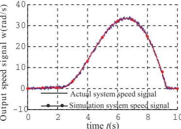
K K ⎠where, L=8; the acceptable errorε =10−4; N = 1000. The parameters of positive direction model are identified by using 1000 input-output actual data, and the sampling period is 10ms. The input-output data must reflect the real characters of the motor, which would increase the parameter identification accuracy. The input and actual output signals used to identify the positive model are as shown in Fig.6 and Fig. 7, respectively, in which the input voltage signal of DC motor U shown in Fig. 6 is u1
(
)
[image:4.595.337.507.642.759.2]1 700 / / sin( /10 ) 8.2031 sin( /10 )
[0, 10]
D A
u K t
t
π π t
= ⋅ ⋅ = ⋅
∈
⋅
0 2 4 6 8 10
0 2 4 6 8 10
-57:9
;639/10
8215/3
<+.,
9240 =+8,
0 2 4 6 8 10 -10
0 10 20 30 40
>684 B+=,
.2>?17 =A=>48 =;443 =65917 068?71>6:9 =A=>48 =;443 =65917
/?>;?>
=;443
=65917
[image:5.595.314.530.55.217.2]@+<13-=,
Fig.7 Output angular speed signal generated by u1
The parameters of negative direction model are also identified by using 1000 input-output actual data, and the sampling period is 10ms. The input and actual output signals are as shown in Fig.8 and Fig. 9, respectively, in which the input voltage signal of DC motor shown in Fig. 8 is
2
u
(
)
[image:5.595.67.254.63.196.2] [image:5.595.62.263.317.485.2] [image:5.595.68.255.515.637.2] [image:5.595.321.525.526.771.2]2 400 / / sin( /10 ) 4.6875 sin( /10 )
[0, 10]
D A
u K t
t
π
= − ⋅ ⋅ = − ⋅ ⋅
∈
t
π
0 2 4 6 8 10
-5 -4 -3 -2 -1 0
.,-+ 02>3
4
;=
@?
A
<
:?687
>98
;
6:
/253
Fig.8 Input signal u2 used to identify the negative model
0 2 4 6 8 10
-30 -20 -10 0 10
.2>?17=A=>48=;443=65917 068?71>6:9=A=>48=;443=65917
>684B+=,
/?>
;
?>
=;
443
=
659
1
7@
+
<1
3-=
,
Fig.9 Output angular speed signal generated by u2
The errors between the responses of simulation system and actual system are very small as displayed in Fig.7 and Fig. 9. Parameter identification results are as shown in TABLE 1. The total generations of evolution is 100 and the population size is 80 by using GA, so the total iteration number of the fitness function is 8000. The simplex method would converge to the global optimal point after about 1500 iterations of objective function. The total time consumption of the program is about 1000s.
TABLE I
PARAMETER IDENTIFICATION RESULTS Positive direction
parameters
Negative direction parameters
K1 0.0110 0.0265
K2 16.1656 35.9636
K3 50.6626 48.0351
K4 1.3142 0.4960
K5 20.8965 10.3105
K6 19.2766 19.3476
K7 16.2566 1.1782
K8 0.0035 0.0078
C. Verification of derived system parameters
In order to verify the parameter identification results, the parameters of positive and negative direction models need to be switched when the running direction of DC motor changes. The parameters of the system are switched to the positive direction model, when the motor running in positive direction; on the other hand, the parameters are switched to the negative one. In this sub-section, different frequency and amplitude voltage signals are applied to DC motor to verify the parameter identification results.
The tested input voltage signal of DC motor shown in Fig. 10 is
3
u
(
)
(
)
(
)
3 / /
/
410/ sin( /10 ) 360/ sin( /5 ) 340/ sin(2 /5 )
4.8047 sin( /10 ) 4.2188 sin( /5 ) 3.9844 sin(2 /5 ), [0, 20]
D A D A
D A
u K t K
K t
t t
t t
π π
π
π π
π
t
= ⋅ ⋅ + ⋅
+ ⋅ ⋅
= ⋅ ⋅ + ⋅ ⋅ +
⋅ ⋅ ∈
⋅
The output angular speed signal of actual system and simulation system generated by input signal are displayed in Fig. 11. The simulation results demonstrate that the errors between the responses of simulation system and actual system are very small in both positive and negative directions, which validates the identification accuracy when the motor runs in the dead and linear zones.
3
u
0 5 10 15 20
-10 -5 0 5 10
.,-+ 02>3
4
;=
@?
A
<
:?687
>98
;
6:
/253
Fig.10 Input voltage signal u3
0 5 10 15 20
-40 -20 0 20 40
/?>
;
?>
=;
443
=
659
1
7@
+
<1
3-=
,
>684B+=,
.2>?17=A=>48=;443=65917 068?71>6:9=A=>48=;443=65917
The tested input slope voltage signal shown in Fig. 12 is
4
u
4 1/ / (1000 100 ) 11.7188 1.1719 [0, 20]
D A
u K t
t
= ⋅ − ⋅ = −
∈
t
⋅
The output angular speed signal of actual system and simulation system generated by input signal are shown in Fig. 13 from which one can see that when the angular speed of the motor reaches to -33.5rad/s, the motor gets to the saturation zone. At this zone, the errors between output signal of simulation system and actual system are also very small.
4
u
0 5 10 15 20
-20 -10 0 10 20
9240 =+8,
-57:9
;639/10
8215/3
<
+
.
,
Fig.12 Input voltage signal u4
0 5 10 15 20
-40 -20 0 20 40 60
/?>
;
?>
=;
443
=
659
1
7@
+
<1
3-=
, .2>?17=A=>48=;443=65917
068?71>6:9=A=>48=;443=65917
>684B+=,
Fig.13 Output angular speed signal generated by u4
V. CONCLUSION
In this paper, GA and simplex method are used to identify the parameters of nonlinear DC motor model. Using the global search ability of GA and the fast convergence of simplex method, the accuracy and efficiency of parameter identification are increased significantly. This method only uses a set of sufficient excitation input-output data of the actual system and can be extended to identify other nonlinear systems conveniently. The simulation results demonstrate the efficiency and correctness of the proposed method. The parameters of
nonlinear DC motor model are identified accurately, and the input-output data of actual system verify higher precision of the identification results by means of the method proposed.
REFERENCES
[1] B. Armstrong-helouvry, P. Dupont, C. Wit Canudas, “A survey of models, analysis tools and compensation methods for the control of machines with friction”, Automation, vol. 30, no. 7, pp: 1083-1138, 1994.
[2] S. Cong, A. De Carli “Two advanced control strategies for dynamic friction compensation”, Acta Automatic Sinica, vol. 24, no. 2, pp. 236-240, 1998. (in Chinese)
[3] S. Cong, et al., “Establishment of simulation model system for nonlinear DC motor”, Journal of System Simulation, vol. 13, no. 1, pp. 25-27, Jan. 2001. (in Chinese)
[4] J. H. Holland, Adaptation in Natural and Artificial Systems, Ann Arbor: University of Michigan press, 1975.
[5] K. S. Huang, Q. H. Wu and D. R. Turner, “Effective identification of induction motor parameters based on fewer measurements”,
IEEE Trans. Energy Conversion, vol. 17, no.1, pp. 55-60, Mar. 2002.
[6] W. H. Tang, Q. H. Wu and Z. J. Richardson, “A simplified transformer thermal model based on thermal-electric analogy”,
IEEE Trans. Power Delivery, vol. 19, no. 3, pp. 1112-1119, Jul. 2004.
[7] Leehter Yao and Willian A. Sethares, “Nonlinear parameter estimation via the genetic algorithm”, IEEE Trans. Signal Procession, vol. 42, no. 4, pp. 927-935, Apr. 1994.
[8] Chunki Kwon and Scott D. Sudhoff, “A Genetic Algorithm Based Induction Machine characterization Procedure”, IEEE Electric Machines and Drives Conference, pp. 1358-1364, May 2005. [9] F. Alonge, F. D’lppolito, G. Ferrante, F. M. Raimondi, “Parameter
identification of induction motor model using genetic algorithms”,
IEE Proc. Control Theory Appl., vol. 145, no. 6, pp. 587-593, Nov. 1998.
[10] Bachir Abdelhadi, Azeddine Benoudjit and Nasreddine Nait-Said, “Application of genetic algorithm with a novel adaptive scheme for the identification of induction machine parameters”, IEEE Trans. Energy Conversion, vol. 20, no.2, pp. 284-291, Jun. 2005.
[11] P. Pillay, R. Nolan, and T. Haque, “Application of genetic algorithms to motor parameter determination for transient torque calculations”, IEEE Trans. Ind. Applicat., vol. 33, pp. 1273–1282, Sept. /Oct. 1997.
[12] K. S. Huang, W. Kent, Q. H. Wu, and D. R. Turner, “Parameter identification of an induction machine using genetic algorithms”, in
Proc. IEEE Int. Symp. Computer Aided Control System Design, vol. 1, pp. 510–515, 1999.
[13] H. Razik, C. Defranoux, and A. Rezzoug, “Identification of induction motor using a genetic algorithm and a quasi-Newton algorithm”, in Proc. IEEE Power Electronics Congress CIEP, pp. 65–70, Oct. 2000.
[14] R. Escarela-Perez, T. Niewierowicz, and E. Campero-Littlewood, “Synchronous machine parameters from frequency-response finite-element simulations and genetic algorithms”, IEEE Trans. Energy Convers., vol. 16, no. 2, pp. 198–203, Jun. 2001.
[15] Dionysios C. Aliprantis, Scott D. Sudhoff and Brian T. Kuhn, “Genetic algorithm-based parameter identification of a Hysteretic Brushless Exciter Model”, IEEE Trans. Energy Conversion, vol. 21, no. 1, pp. 148-154, Mar. 2006.
[16] Kanako Miura, et al., “Robust and uncalibrated visual servoing without Jacobian using a simplex method”, Proc. IEEE Int. Conference on Intelligent Robots and Systems, vol. 1, pp. 311-316, Sept. 2002.