Abstract—The aim of this paper is to determine the valid orientations of the inspection devices used in probe operations and non-contact scanning operations on a Coordinate Measuring Machine (CMM). The methodology applied is based on the accessibility analysis and the application of ray-tracing techniques. This analysis will take into account the real shape and geometry of the inspection device and the constraints imposed by the CMM on which it is mounted. Likewise, different algorithms based on computer graphics have been applied to speed up the searching of valid orientations.
Index Terms—Accessibility, CMM, inspection, probe, laser stripe, scanning.
I. INTRODUCTION
Among the activities of an automatic process planning system for inspection on a Coordinate Measuring Machine (CMM), the determination of inspection device orientation with regard to the part stands out. These inspection device orientations are obtained from a methodology based on the accessibility analysis [1] and the application of ray-tracing algorithms [2]. Moreover, different computer graphics techniques like space partitioning and back-face culling have been applied in order to speed up the searching of valid orientations.
The methodology has been applied to inspection processes based on a touch-trigger probe [3] and to non-contact scanning processes based on a laser stripe [4]. In both cases, different constraints have been considered: real shape and dimensions of the inspection devices, process parameters and possible orientations of the motorized head of the CMM where the inspection device has been mounted. This motorized head (PH10MQ) provides 720 feasible orientation of the inspection device by rotating at a resolution of 7.5º about both horizontal and vertical axes (A, B).
Manuscript received March 18, 2008. This work is part of the results obtained in a research project supported by the Spanish Education and Science Ministry (MEC-04-DPI2004-03517) and FEDER.
B. J. Álvarez and P. Fernández have collaborated with the Manufacturing Engineering Department of the University of Oviedo for developing the research project mentioned above (e-mail author: [email protected]).
J. C. Rico is a Professor (e-mail author: [email protected]). G. Valiño is a Senior Lecturer (e-mail author: [email protected]).
The corresponding address for all authors is: Department of Manufacturing Engineering, University of Oviedo, Campus de Gijón, 33203 Gijón, SPAIN.
II.ANALYSIS METHODOLOGY
The accessibility analysis for a touch-trigger probe deals with determining all the feasible probe orientations that allow for performing the part inspection avoiding collisions with the part or any other obstacle in the environment of the inspection process. Moreover, the valid orientations of the non-contact scanning device will be obtained to guarantee the visibility of the surface to be scanned. The methodology applied in both cases will be exactly the same. First, a local analysis will be made for each part surface by taking into account the inspection device as an infinite half-line whereas the possible interferences with the rest of part surfaces or any other obstacle are ignored. Hence, valid orientations lG will be those which make an angle between 0 and π/2 with the normal vector nG to the analyzed surface.
In a second analysis stage, the orientations obtained in the local analysis will be checked in order to determine if they have or not collision with the rest of part surfaces or any other obstacle. This analysis is called global analysis and it is complex and expensive from a computational point of view because it involves the calculation of multiple interferences tests. To make this calculation easier, a STL model of the part is used, where each surface is discretized by a set of triangles. Thus the global accessibility analysis is reduced to determine if there exist interferences between orientations lG obtained in the local analysis and the triangles that compose the STL model of either the part or the obstacle.
Moreover, in order to further reduce the calculation time, different computer graphics techniques like space partitioning based on kd-tree, ray traversal algorithm, back-face culling and ray-triangle intersection tests have been also applied [5].
The use of space partitioning structures like kd-trees allows for reducing the number of the triangles to test in the global analysis because it involves checking intersection exclusively with triangles which can potentially be traversed by each inspection device orientation. The part is partitioned in regions bounded by planes (bounding boxes) and each part triangle is assigned to the region within which it is located. Then, regions traversed by each inspection device orientation are selected by means of the ray-traversal algorithm that was first developed and applied by Kaplan [2].
Before checking intersection between each inspection device orientation and all triangles included in the traversed regions previously determined, the number of intersection
Accessibility Analysis for the Automatic Contact
and Non-contact Inspection on Coordinate
Measuring Machines
tests can be reduced even more by applying a back-face culling algorithm [5]. Thus, from the initial set of triangles included in the traversed regions, a subset is extracted that do not include those triangles whose visibility according to an analysed inspection device orientation is completely blocked by other triangles.
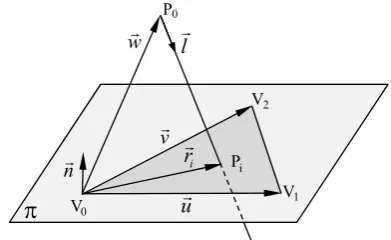
Finally, the intersection test between each undiscarded triangle and the inspection device orientation lGis carried out. The triangles of the STL format are defined by its vertices V0, V1 and V2 and normal unitary vector nG. If the next equation (Fig. 1) is satisfied:
0
n lG⋅ =G (1)
the orientation lGwill be parallel to the supporting plane of the triangle and therefore there will be no intersection. If both the expression (1) and the next condition are satisfied:
0
n wG G⋅ = (2)
then the inspection device orientation lGwill be contained in the plane. In expression (2) wGis a vector with origin at vertex V0 and end at point P0. When this orientation intersects or coincides with any of the triangle edges, then, intersection between device orientation and triangle occurs.
If none of the previous relationships is fulfilled, then there is intersection between the inspection device orientation
l
G
and the supporting plane of the triangle. The intersection point Pi can be expressed as (Fig. 1):
0 i
n w
P P l
n l
⋅ = − ⋅
⋅
G G G G
G (3)
Finally, it is necessary to check if this point Pi lies inside the triangle defined by the three vertices V0, V1 and V2. This verification is based on the algorithm developed by Möller and Trumbore [6]. The equation of the supporting plane of the triangle V0, V1 and V2 can be expressed as:
0 ( , )
V s t =V + ⋅ + ⋅s u t vG G (4)
where uG and vG are two edge vectors of the triangle with common origin at V0. A point Pi located on the plane (4) will be inside the triangle if there exist values si ≥0 and ti ≥0
vG
i
0
V V1
2 V 0
P
π
P wG lG
uG
nG ri
[image:2.595.311.539.51.409.2]G
Fig. 1. Intersection between laser beam lGand a triangle facet V0V1V2.
Stylus
Tip Touch probe Column
Head Machine
Prism
Sphere
Capsule
(a) Touch-trigger probe
Column
Head Machine
Adapter
Head Laser
Prism
Sphere
Capsule
Prism
[image:2.595.74.270.628.748.2](b) Laser stripe system
Fig. 2. Components of the inspection device and their simplified models. that satisfies the next equation:
0
i i i
P V− = ⋅ + ⋅s u t vG G (si+ ≤ti 1) (5) If the point lies within the triangle then there will be
intersection and the analysis will continue with another triangle. If there is still no interference, the orientation will be considered as valid.
III. INTERFERENCE ANALYSIS CONSIDERING REAL DIMENSIONS OF THE INSPECTION DEVICE
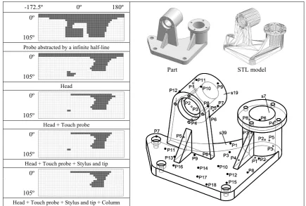
The orientations obtained in previous sections are based on an ideal representation of the inspection device as an infinite half-line. To check if these orientations are really valid will be necessary to take into account the real shape and dimensions of the inspection device. Therefore, intersection between triangles of the STL part model and each of the inspection device components must be checked. Fig. 2 shows the components for each of the inspection devices that have been considered in this work:
1) Touch-trigger probe: column, head, touch probe, stylus and tip (Fig. 2a).
2) Laser stripe system: column, machine head, adapter and laser head (Fig. 2b).
straight prisms, the machine head by a sphere and the laser adapter, touch probe and stylus by a capsule.
Similarly to section 2, a kd-tree algorithm has been implemented in order to test exclusively the interference between each of the inspection device components and the triangles included in the part regions that they traverse. To carry out this task effectively, each inspection device component is enclosed in a bounding volume and only the part regions that overlap with that volume are analysed. Then, intersections between part triangles included in these regions and the component are checked. Since several geometrical shapes have been used to model the components of each inspection device, different algorithms for checking intersections are applied:
1) Sphere-triangle intersection algorithm to analyse interferences with the machine head [7]. This algorithm simply calculates the minimum distance between a point (sphere centre) and a triangle. If this distance is smaller than the radius of the sphere, intersection will occur. 2) Prism-triangle intersection algorithm to analyse
interferences with the column. This algorithm derives from the separating axis theorem which was initially developed to determine if two convex polyhedral are disjoint [8]. The theorem states that two convex polyhedra, A and B, are disjoint if they can be separated along either an axis parallel to a normal of a face of either A or B, or along an axis formed from the cross product of an edge from A with an edge from B. The application of this theorem to a prism-triangle test involves checking their relative position with regard to different potential separation axes [9].
3) Capsule-triangle intersection algorithms to analyse interferences with the touch probe and the stylus-tip [10]. In this case, intersection analysis is based on finding the minimum distance between each edge of the triangle and the capsule line segment, as well as the minimum distance between each extreme point of the capsule segment and the triangle. If any of these distances is smaller than the radius of the capsule, then intersection will occur.
IV. CLUSTERING
From the previous analysis, the inspection device orientations that are valid for probing each point or scanning each part triangle have been determined. These orientations are mathematically represented by means of a binary matrix A q ri( , ) where each element corresponds to a combination of discrete values of A and B angles:
( )
1 if (A = , B = )
is a valid orientation for point P ,
0 if (A = , B= )
is a not valid orientation for point P
q r i i q r i a b
A q r
a b ⎧ ⎫ ⎪ ⎪ ⎪ ⎪ = ⎨ ⎬ ⎪ ⎪ ⎪ ⎪ ⎩ ⎭ (6)
To reduce the process operation time related to device orientation changes, orientations (aq, br) common to the greatest number of points to probe (clusters of points) or triangles to scan (clusters of triangles) must be found. The classification of points or triangles continues until no intersection can be found between the final clusters.
-172.5º 0º 180º
Part STL model
P7 P11 P13 P16 P5 P9 P6 P14 P17 P18 P10 P12 P15 P8 P1 P2 P2 P5 P3 P6 P8 P4 P1 P3 P7 P4 P6 P5 P8 P7 P3 P2 P12 P1 P11 P10 P9 s19 s39 s7 P4 P7 P11 P13 P16 P5 P9 P6 P14 P17 P18 P10 P12 P15 P8 P1 P2 P2 P5 P3 P6 P8 P4 P1 P3 P7 P4 P6 P5 P8 P7 P3 P2 P12 P1 P11 P10 P9 s19 s39 s7 P4 0º 105º
Probe abstracted by a infinite half-line 0º
105º
Head 0º
105º
Head + Touch probe 0º
105º
Head + Touch probe + Stylus and tip 0º
105º
[image:3.595.79.515.443.736.2]Head + Touch probe + Stylus and tip + Column
The algorithm used for clustering is similar to that developed by Vafaeesefat and ElMaraghy [11]. Next, the algorithm is explained for an inspection process using a touch-trigger probe.
Each point Pi (i = 1, 2, …, n) to be probed is associated to a binary matrix of valid orientations k
i
A (i = 1, 2, …, n). Initially (k = 1), the clusters will be the same as each of the points to be probed: k
i i
C =P. Starting from the clusters k
i
C and from the binary matrices k
i
A , a new matrix k( , ) k k
i j
CI i j =A ∩A is built showing the common probe orientations to the clusters two against two.
With the purpose of creating clusters whose points are associated with the greatest number of valid orientations, the algorithm searches the indices (s, t) of CIkthat correspond to the maximum number of common valid orientations. After that, clusters k
s
C and k t
C associated to points Ps and Pt respectively will be regenerated as follows:
k k k
s s t
C =C ∪C and k t
C = ∅ (7)
and the binary matrix of valid orientation associated to the new cluster k
s
C will be k k k
s s t
A =A ∩A .
With these new clusters, matrix CIkis updated to:
for and
( , )
for and
k k
k Ai Aj i t j s
CI i j
i t j t
⎧ ∩ = = ⎫ = ⎨∅ = = ⎬
⎩ ⎭ (8)
The clustering process finishes when the number of common orientations corresponding to all the elements above the main diagonal of matrix CIkhave become zero. A similar process is used to determine the clusters of triangles Ti (i = 1, 2, …, n) for a part to be scanned.
V. APPLICATION RESULTS
A. Inspection Process by means of a Touch-trigger Probe In order to analyze the application results of accessibility and clustering algorithms to the inspection process, the part shown in Fig. 3 has been considered. For this part, the STL model contains 2438 triangles and 38 inspection points located on three different surfaces (s7, s19 and s39). As an example, Fig. 3 shows the accessibility maps for the inspection point P4s39 (point P4 on surface s39) considering the different geometrical abstractions of the probe. As it can be seen, when real dimensions and different probe components are taken into account, the accessibility map is substantially reduced. For the rest of inspection points, similar accessibility maps can be obtained.
Furthermore, the application of the clustering algorithm allows for obtaining the clusters shown in Table I. In this case seven clusters have been found.
B. Scanning process by means of a Laser Stripe System Apart from the inspection process, the developed methodology allows for determining the orientations of a laser stripe system to scan a part. In this type of scanning systems a laser stripe of known width is projected onto the part surface to be scanned and the reflected beam is detected
TABLE I.CLUSTER OF POINTS AND COMMON ORIENTATIONS IN THESE CLUSTERS
Cluster Points / Surface Orientations (A, B)
1 P1s19, P2s19, P12s19, P4s7, P4s39, P7s39, P11s39, P13s39
(37.5, 67.5) (45, 67.5)
2 P3s19, P1s39, P5s39, P6s39 (67.5, -60)
3 P4s19, P5s19 (97.5, -90) (97.5, -82.5) (97.5, -75) (97.5, -67.5) (97.5, -60) 4 P6s19, P8s7 (30, -165) (30, 180) (37.5, -172.5) (37.5, -165) (37.5, -157.5)
(37.5, -150) (37.5, -142.5) (37.5, -135) (37.5, 157.5) (37.5, 165) (37.5, -172.5) (37.5, 180) (45, -172.5) (45, -165) (45, -157.5) (45, -150) (45, -142.5) (45, -135) (45, -127.5) (45, -120) (45, 180) (52.5, -172.5) (52.5, -157.5) (52.5, -150) (52.5, -142.5) (52.5, -135) (52.5, -127.5) (52.5, -120) (52.5, -112.5)
5 P7s19, P8s19, P9s19, P10s19, P11s19, P6s7, P2s39, P3s39, P8s39, P9s39, P10s39, P12s39, P14s39, P15s39, P16s39, P17s39, P18s39
(15, 120) (15, 127.5) (22.5, 112.5) (22.5, 120) (22.5, 127.5) (22.5, 135) (22.5, 142.5) (22.5, 150) (22.5, 165) (30, 112.5) (30, 120) (30, 127.5) (30, 135) (30, 142.5) (30, 150) (30, 165)
6 P2s7, P3s7 (7.5, -15)
by a CCD camera. Therefore, not only the incident laser beam orientation has been taken into account for the accessibility analysis but also the possible occlusion due to the interference of the reflected laser beam with the part.
Fig. 4 shows the laser head orientation map associated to the local and global accessibility analysis for triangle 558 of the example part. The darkest colour represents the head orientations (A, B) that coincide or are closest to the normal direction of the triangle analyzed. These are considered as optimal orientations. Grey colours represent head orientations far from the optimal value which lead to worse scanning quality. White colour represents head orientations
that do not enable to scan the considered triangles. For a better visualization of the orientation map, increments of 15º have been considered for angles A and B.
For triangle 558 an incident laser beam orientation (A=30º, B=180º) has been selected in order to show the part regions (bounding boxes) that it traverses (Fig. 5). Triangles partially or totally enclosed in these bounding boxes are shown in the figure before and after applying the back-face culling algorithm.
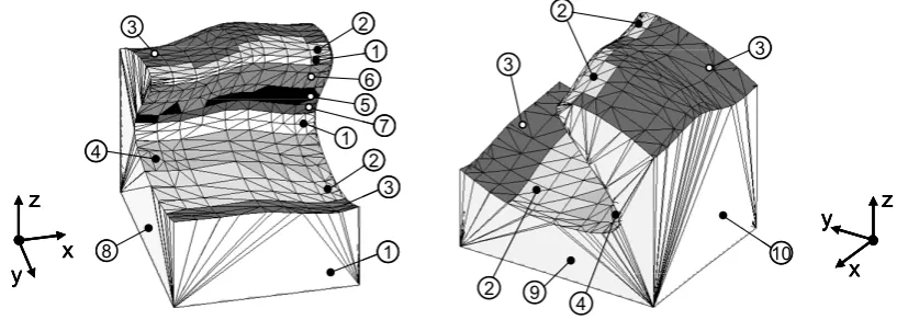
Fig. 6 shows in a grey scale the ten triangle clusters obtained for the example part.
Triangle 558
-180 º 0 º +180º
Local orientations
(A, B) 0º
105º
Global orientations
(A, B) 0º
[image:5.595.109.489.216.369.2]105º
Fig. 4. Local and global accessibility maps for triangle 558
(a) Triangle 558 and incident ray orientation A30-B180
(b) Part regions traversed by the incident ray
(c) Triangles within the traversed part regions
(d) Triangles within the traversed part regions after applying the back-face culling
[image:5.595.67.534.400.554.2]algorithm
Fig. 5. Different stages to determine the global visibility map for a triangle (558) and an incident laser beam orientation (A=30º, B=180º).
1
1
1 3
3 2 2
4
5 6
7
8
3 3
2
9 4
10
2 x
y z
y x
z
1
1
1 3
3 2 2
4
5 6
7
8
3 3
2
9 4
10
2 x
y z
x
y z
y z
y x
z
y x
[image:5.595.91.500.595.741.2]z
VI. CONCLUSIONS
Most of the accessibility analysis presented in other works only deal with a limited number of the inspection device orientations, simple parts with only planar surfaces or specific geometrical shapes, simplified device representations or a short number of points in the case of inspection by touch-trigger probe. However, in this paper, a new methodology for accessibility analysis is presented which allows for overcoming the previous limitations: 1) The methodology has been extended to the inspection
process by means of a touch-trigger probe and the scanning process by means of a laser stripe system. 2) All the possible orientations (720) of the inspection
device are taken into consideration.
3) The use of the STL model permits the application of the developed system to any type of part, regardless of its shape and complexity.
4) The real shape and dimensions of the inspection device are considered for the analysis.
5) The implemented algorithms based on Computer Graphics reduce computation time and consequently can deal with a high number of inspection points and complex surfaces.
6) Moreover, a clustering algorithm is applied that efficiently groups the inspection points and triangles of the STL of the part to be scanned in order to reduce the number of probe orientation changes.
The developed system has been applied to different parts with satisfactory results demonstrating the application in
practice. Future research will concentrate on developing new algorithms that further reduce computation time, and on generating the inspection paths from the orientations obtained in the clustering process.
REFERENCES
[1] A. J. Spyridi and A. A. G. Requicha, “Accessibility analysis for the automatic inspection of mechanical parts by coordinate measuring machines,” Proc. of the IEEE Int. Conf. on Robotics and Automation, 1990, pp. 1284-1289.
[2] M. Kaplan, “Space-tracing: A constant time ray-tracer,” Proceedings of the SIGGRAPH’85, 1985, pp. 149-158.
[3] A. Limaiem and H. A. ElMaraghy, “CATIP: A Computer-Aided tactile inspection planning system,” Int. J. of Prod. Res., vol. 37(3), 1999 pp. 447-465.
[4] K. H. Lee and H. -P. Park, “Automated inspection planning of free-form shape parts by laser scanning,” Robot. Comput. Integr. Manuf., vol. 16(4), 2000, pp. 201-210.
[5] J. D. Foley, A. van Dam, S. K. Feiner and J. F. Hughes, Computer Graphics, Principles and Practice, Cornell: Addison-Wesley, 1995, ch. 15, pp. 663-664.
[6] T. A. Möller and B. Trumbore, “Fast, minimum storage ray/triangle intersection,” Journal of Graphics Tools, vol. 2(1), 1997, pp. 21-28. [7] P. J. Schneider and D. H. Eberly, Geometrical Tools for computer
graphics, San Francisco: Morgan Kaufmann Publishers Inc., 2003, ch. 10, pp. 376-382.
[8] S. Gottschalk, M. C. Lin and D. Manocha, “OBBTree: a hierarchical structure for rapid interference detection,” Proc. of the SIGGRAPH’96, 1996, pp. 171-180.
[9] T. A. Möller, “Fast 3D triangle-box overlap testing”. Journal of Graphics Tools, vol. 6(1), 2001, pp.29–33.
[10] D. H. Eberly, 3D Game engine design. A practical approach to real-time computer graphics, San Diego: Morgan Kaufmann Publishers Inc., 2000, ch. 2, pp. 53-57.