Abstract—This paper proposed a speech-controlled real-time remote vehicle on-board diagnostic (OBD) system for telematics applications. The proposed system contains three main parts. They are OBD embedded global position system (GPS-OBD) module, speech-controlled interface, and vehicle surveillance server. In addition to the real-time vehicle time-location information including date, time, longitude, and latitude obtained from GPS receiver, the GPS-OBD module can also record the real-time vehicle operation information including vehicle speed, engine rpm, coolant temperature, battery voltage, fault code number, and others from OBD system. These real-time vehicle data, i.e., vehicle time-location and operation information, will be uploaded to the vehicle surveillance server via 3.5G network. Meanwhile, the GPS-OBD module can be operated through the speech-controlled interface. The derivers therefore could safely operate the proposed system via speech commands and keep their eyes on the road. The vehicle surveillance server is designed to provide real-time vehicle information retrieve service for authorized supervisors or servicemen. One can use a specific browser co-operated with Google Maps to retrieve real-time vehicle information, e.g., date, time, speed, vehicle location, and etc of the monitored vehicle. The proposed system is very useful for the detection of vehicle pollution, warning of vehicle malfunction, remote diagnosis, and roadside repair.
Index Terms—Telematics,On-Board Diagnostic (OBD), Global Position System (GPS), Speech-controlled interface.
I. INTRODUCTION
On-board diagnostic (OBD) system is designed to monitor the operation condition of vehicle and provide diagnostic information or standardized fault codes for malfunctions [1]-[3]. As early as in 1985, the California Air Resources Board (CARB) enacted an ordinance that demands the vehicles outfitted with the first generation OBD system. Due to some defects of design, the first generation OBD was then replaced by the second generation OBD, called OBD-II, in 1996. The European Union followed to legislate for a compulsory installation of compatible OBD-II system. The Environmental Protection Administration, Taiwan, also declared a mandatory regulation in Jan. 2008 for its Phase 4 Emission Standards against all the vehicles sold in Taiwan. Therefore it is a tendency that all of the vehicles will equip with OBD system as
Manuscript received Jan. 11, 2010. This work was supported in part by National Science Council (NSC), Taiwan, under Grant 98-2220-E-366-001-.
Shi-Huang Chen* and YuRu Wei are with the Department of Computer Science & Information Engineering, Shu-Te University, Yanchao, Kaohsiung County, Taiwan (R.O.C.) (*e-mail: [email protected]).
a standard equipment.
The OBD system can consecutively monitor the running condition of vehicle. Once there is a malfunctioning element that controls the emission of exhaust, the OBD system will turn on the Malfunction Indicator Lamp (MIL) or the Check Engine light in the in-car dashboard to notify the driver to repair the car immediately. When the OBD system detects a malfunction, OBD regulations will inform the Electronic Control Unit (ECU) of the vehicle to save a standardized Diagnostic Trouble Code (DTC) about the information of malfunction in the memory. An OBD Scan Tool for the servicemen can access the DTC from the ECU to quickly and accurately confirm the malfunctioning characteristics and location in accordance with the prompts of DTC that shortens the service time largely. It follows from SAE standards [1]-[3], currently OBD can monitor more than 80 items of real-time driving status, e.g., vehicle speed, engine rpm, engine coolant temperature, battery voltage, and etc.
Although OBD system can help servicemen to shorten the diagnostic time of vehicle, it has an operation problem. That is the OBD system usually needs to acquire data from running engine or vehicle in moving conditions. The traditional OBD operation interface is in the form of buttons or knobs. The drivers or servicemen have to remove their eyes from the road to operate these OBD buttons or knobs. It goes without saying that it will result in a driving safety problem. In addition, a demand for the immediateness and mobility relevant to the vehicular diagnostics is growing increasingly. It is desirous that the DTC as well as current status of vehicle can be delivered to the authorized service center through the mobile communication system, such as GPRS or 3.5G network. Hence, servicemen can inquire the real-time malfunction message from a remote vehicle [4]-[5]. To overcome the above problem, this paper proposed a speech-controlled real-time remote vehicle OBD system. The proposed system comprised of OBD embedded global position system (GPS-OBD) module, speech controlled interface, and vehicle surveillance server. The configuration of the proposed system is shown in Fig. 1.
The proposed system makes use of a speech-controlled interface, instead of traditional buttons or knobs, to operate the OBD. The drivers or servicemen can operate the OBD system without removing their eyes from the road. It will obviously increase the safety for operating OBD system. The GPS-OBD module can record the real-time vehicle time-location and operation information including date, time, longitude, latitude, vehicle speed, engine rpm, coolant temperature, battery voltage, fault code number, and others from GPS and OBD systems.
A Study on Speech-Controlled Real-Time
Remote Vehicle On-Board Diagnostic System
These real-time vehicle data, i.e., the vehicle time-location and operation information, will be uploaded to the vehicle surveillance server via 3.5G network. Furthermore, the proposed system will notify the derivers when GPS-OBD module detects any fault code or abnormal condition. The vehicle surveillance server can provide real-time vehicle information retrieve service for authorized supervisors or servicemen. One can use a specific browser co-operated with Google Maps to retrieve real-time vehicle information, e.g., date, time, vehicle speed, vehicle location, engine condition, and etc. The proposed system is very useful for the detection of vehicle pollution, warning of vehicle malfunction, remote diagnosis, and roadside repair.
Fig. 1. Configuration of proposed speech-controlled real-time remote vehicle OBD system.
The remainder of this paper is organized as follows. Sections II, III, and IV will introduce the proposed GPS-OBD module, speech controlled interface, and vehicle surveillance server, respectively. Section V will discuss the experimental results. Finally, the conclusions will be given in Section VI.
[image:2.595.52.284.504.695.2]II. GPS-OBD MODULE
Fig. 2. Block diagram of system of the proposed GPS-OBD module.
The GPS-OBD module is the most important component in the proposed system. It is designed to acquire the real-time
vehicle time-location and operation information, e.g., date, time, longitude, latitude, speed, engine rpm, coolant temperature, battery voltage, fault code number, and others from GPS receiver and OBD-II to Bluetooth adapter. The real-time vehicle information will be encoded via OBD-II diagnosis encoder and then become digital bit streams. The GPS-OBD module will transmit these digital bit-streams to the vehicle surveillance server through the 3.5G network. In addition, the operation of GPS-OBD module is by the speech-controlled interface. Fig. 2 is the block diagram of the proposed GPS-OBD module. The system is mainly comprised of OBD-II to Bluetooth adapter, GPS receiver, OBD-II diagnosis encoder, and 3.5G wireless network module. The following three subsections will particularly introduce these three main items.
A. OBD-II to Bluetooth adapter
OBD-II was proposed in 1996 to replace the deficient former system, namely OBD-I. The specifications of OBD-II were recognized by the Environmental Protection Agency (EPA), US, and California Air Resources Board for air-pollution control. Since 1996, all vehicles are required to be equipped with OBD II under EPA regulation in the USA. When vehicle exhausts higher level of air-pollution contents, OBD-II will generate Diagnostic Trouble Code (DTC) messages and Check Engine light will display. Some symbols of Check Engine lights are shown in Fig. 3. Meanwhile, OBD-II will save this DTC in the memory inside ECU. Thus the DTC messages can be retrievable through an OBD-II scan tool [1]-[3].
Fig.3. Variety of icons of Check Engine light.
The main features of OBD-II are (1) unified J1962 16-pin socket and data link connector (DLC) (as shown in Fig. 4); (2) unified DTC and meanings; (3) storage and display DTC; (4) contains vehicle record capability; and (5) auto-clear or reset function for the DTC [3]. Hence, the advantage of OBD-II is its standardization. In other words, just one set of OBD-II scan tool is able to perform the diagnosis and can scan against variety of vehicles which equipped with OBD-II system.
(a) (b) Fig. 4. (a) J1962 OBD-II 16-pin socket, (b) OBD-II DLC.
[image:2.595.316.525.633.718.2]fixed functions and the rest pins are left to the discretion of the vehicle manufacturer [3]. Table I tabulates the functions of OBD-II 16 pins socket in details.
Fig. 5. Definition of the OBD-II Diagnostic Trouble Code
There are five codes in total to represent the OBD-II DTC message. Fig. 5 shows the definition of the OBD-II DTC. The first code is an English alphabet to stand for the established malfunction system. The remaining four codes are digits; the second code indicates the meaning of malfunction formulated by ISO/SAE or customized by the vehicle manufacturer; the third code shows the area of vehicle system; the remaining two codes represent the definition of the subject malfunction [1]. In summary, P01xx and P02xx belong to oxygen mixed ratio group; P03xx belongs to sparking system group; P04xx belongs to exhaust system group; P05xx belongs to vehicle speed system and vehicle idle control system; P06xx belongs to vehicle ECU system and the level of output code; P07xx and P08xx belong to transmission group; P09xx and P00xx are reserved for ISO/SAE.
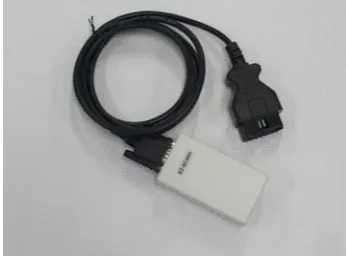
[image:3.595.44.292.158.546.2]Because the OBD-II interface is not a standard equipment of general computer, an OBD-II to Bluetooth adapter was fabricated to accommodate with the GPS-OBD module to acquire the real-time vehicle status. The proposed system selects EZ-SCAN5 as the OBD-II to Bluetooth adapter. Fig. 6 is a surface photo of EZ-SCAN5. EZ-SCAN5 supports most of OBD-II communication protocols including SAE J1850 PWM, SAE J1850 VPW, ISO 9141-2, ISO 14230-4 KWP, and ISO 15765-4 CAN. The OBD-II messages will be decoded and transmitted to OBD-II diagnosis encoder via EZ-SCAN5.
Fig. 6. EZ-SCAN5 OBD-II to Bluetooth adapter.
B. GPS receiver
GPS receiver can receive signals from 8-12 sets of GPS satellite at the same time. The GPS satellite signals include coordinated universal time, ephemeris data, almanac data, coarse/acquisition code, and etc. GPS receiver can receive, process, and transform the information into time, latitude, longitude, velocity, orientation, altitude, estimated position error, and etc. For example, a sentence amongst the GPS information sentences is as follows: $GPGGA, 055730.367, 2238.2122, N, 12017.7504, E, 1, 06, 7.0, 133.9, M, 10.0, M, 0.0, 0000*74; therein, the denotations of respective data are explained below [6]:
` GGA (Global Positioning System Fix Data): Time, position, and fix related data for a GPS receiver.
` 055730.367: UTC time format, fix was taken at 05:57:30 UTC.
` 2238.2122, N: Latitude format, it is 22 degree 38.2122’ of north latitude.
` 12017.7504, E: Longitude format, it is 120 degree 17.7504’ of east longitude.
` 1: Fix quality, the measured indicator 1 indicates that the information has made a fix using GPS.
` 06: The number of satellites was tracked.
` 7.0: Horizontal dilution of position: 0.5 m to 99.9 m, the measured value is 7.0 m.
` 133.9, M: Altitude above mean sea level, the measured altitude is 133.9 m.
` 10.0, M: Height of geoid above World Geodetic System 1984 (WGS 84) ellipsoid , the measured height is 10.0 m.
` 0.0: Time in seconds since last Differential GPS (DGPS) TABLEI
VEHICLE CONNECTOR CONTACT ALLOCATION OF OBD-II
Contact Allocation
1# Discretionary
2# Bus positive line of SAE J1850
3# Discretionary
4# Chassis ground
5# Signal ground
6# CAN_H line of ISO 15765-4
7# K line of ISO 9141-2 and ISO 14230-4
8# Discretionary
9# Discretionary
10# Bus negative line of SAE J1850
11# Discretionary
12# Discretionary
13# Discretionary
14# CAN_L line of ISO 15765-4
15# L line of ISO 9141-2 and ISO 14230-4
[image:3.595.340.514.217.347.2]update, the measured value 0.0 shows that this GPS receiver did not use DGPS fix.
` 0000: DGPS station ID number.
` *74: Checksum.
Then, these data will be transmitted to a Geographical Information System (GIS), such as Google Maps to pinpoint and display the vehicle position. The proposed system used the GPS receiver with the SiRF Star III chipset mounted to collect the GPS signals.
C. OBD-II diagnosis encoder
The function of OBD-II diagnosis encoder is to encode and integrate the GPS signals and OBD information in accordance with the preset transmission format. These encoded digital bit streams will be transmitted to the vehicle surveillance server via 3.5G network. The vehicle surveillance server can decode the digital bit steams in accordance with the predefined transmission format to acquire the subject vehicle information, including speed, engine rpm, battery voltage, engine coolant temperature, OBD DTC, and the GPS coordinates for the position of vehicle.
Since the updating frequency of GPS is 1 Hz, the proposed OBD-II diagnosis encoder is designed to acquire the OBD DTC and the real-time vehicle status every second. Meanwhile, this paper defined a transmission format as follows: License plate ID | GPS data | OBD DTC | OBD data, including vehicle speed, engine rpm, battery voltage, engine coolant temperature and others. With the aim of reducing the transmission bit-rate, this paper only selects the GGA contents amongst the GPS signals as the positioning data and transmitted the OBD DTC as well as OBD data in a decimal system after processing the analytics. For instance:
` License plate ID: AB-1234
` GGA data from GPS: $GPGGA, 055730.367, 2238.2122, N, 12017.7504, E, 1, 06, 7.0, 133.9, M, 10.0, M, 0.0, 0000*74
` DTC: P0123
` Vehicle speed: 57km/hr
` Engine rpm: 1649 rpm
` Battery voltage: 13.3V
` Engine coolant temperature: 95 °C
[image:4.595.315.543.466.597.2]The data for transmission after being encoded by the encoder are: 1043 | $GPGGA, 055730.367, 2238.2122, N, 12017.7504, E, 1, 06, 7.0, 133.9, M, 10.0, M, 0.0, 0000*74 | P0123 | 57, 1649, 13.3, 95
D. 3.5G network module
The 3.5G mobile communication technology is based on a High Speed Packet Access (HSPA) network which consists of HSDPA (High Speed Downlink Packet Access) for downlink and HSUPA (High Speed Uplink Packet Access) for uplink [7]. It represents an enhancement of W-CDMA networks with higher data transfer speeds and improved spectral efficiency. Generally, 3.5G system has a theoretical downlink data-rate peak of 14.4 Mbps and with uplink data-rate of 384 kbps [7]. Therefore 3.5G system provides faster data transfer rates than
other mobile communication technology such as GPRS (2.5G) system and is suitable for the proposed system and other telematics applications.
III. SPEECH CONTROLLED INTERFACE
The speech controlled interface proposed in this paper is to control the OBD-II diagnosis encoder (as shown in Fig. 2). The predefined speech commands include operation instructions, e.g., start, end, next page, previous page, and OBD-II monitored items, e.g., vehicle speech, engine rpm, and etc. The proposed speech controlled interface belongs to text-dependent isolated word recognition and is based on linear predictive coefficient (LPC) and dynamic time warping (DTW) [8]. The main idea behind LPC is that given speech sample can be approximated as a linear combination of the past speech samples. LPC models signal s(n) as a linear combination of its past values and present input. Because in speaker recognition task the present input is generally unknown it is simply ignored. Therefore, the LPC approximation depends only on the past values, which is represented by the equation:
∑
=− −
= P
i
is n i a n
s
1
) ( )
(
ˆ (1) where ŝ(n) is an approximation of the present output, s(n−i) are past outputs, P is the prediction order, and ai are the LPC. The LPC can be easily calculated by the use of Levinson-Durbin algorithm [8]. In this paper, the input speech signal is sampled at 8 KHz with 16-bit resolution and the analysis frame size is 32 msec with 16 msec overlapping. It follows from literatures [9]-[10] that the 10 prediction orders of LPC is enough for text-dependent isolated word recognition.
Fig. 7. Graphical explanation of the basic idea of DTW [11].
dynamic time warping is to find the path w(i) such that it gives the least cumulative difference between the compared signals. Although the recognition performance of the system embedded LPC and DTW is somewhat lower than that of the system made use of mel-frequency cepstral coefficient (MFCC) [8] and hidden Markov model (HMM) [8], the computational complexities of LPC and DTW are also lower than that of MFCC and HMM. Since the range of recognizable words needed in the proposed system is limited, the recognition rate of LPC and DTW is similar to MFCC and HMM. It follows from experimental results given in Section V that the proposed speech controlled interface can achieve satisfied recognition performances.
IV. VEHICLE SURVEILLANCE SERVER
[image:5.595.354.500.186.322.2]The real-time vehicle information, including GPS coordinates, vehicle speed, engine rpm, battery voltage, coolant temperature, OBD DTC, and others, acquired by the GPS-OBD module will be transmitted to the vehicle surveillance server via 3.5G network. The vehicle surveillance server will record the vehicle information from the GPS-OBD module by the Access 2003 database format. The proposed system established a data table to record the vehicle information. As shown in Fig. 8, it contains vehicle license plate ID, date, time, longitude, latitude, and OBD-II descriptions.
Fig. 8. Data table details (partial) of the vehicle status.
[image:5.595.46.292.393.475.2]Then the vehicle status browser can retrieve the real-time or off-line vehicle information, e.g., speed, engine rpm, battery voltage, coolant temperature, OBD DTC, and location of vehicle. In the proposed system, the vehicle status browser makes use of Google Maps as the geographical information system (GIS). In addition to complete API for developers, the most important is that the Google Maps is free of charge.
[image:5.595.326.526.577.729.2]Fig. 9. An example of the layout of the vehicle status browser.
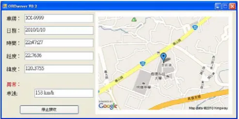
Fig. 9 is an example of the layout of the vehicle status browser. The right part of the vehicle status browser is the
location of vehicle shown in Google Maps. The vehicle driving location at the time is pinpointed with a blue balloon symbol in Google Maps. The vehicle license plate ID, driving date/time, longitude, and latitude are shown in the left part. The OBD DTC and other corresponding message are shown in the “abnormal” block. The OBD-II information, including vehicle speed, engine rpm, battery voltage, and engine coolant temperature will be displayed in another window likes Fig. 10.
Fig. 10. OBD-II information displayer.
V. EXPERIMENTAL RESULTS
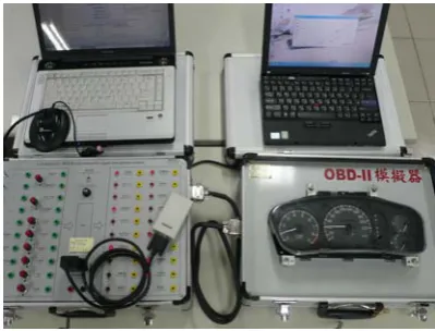
This paper used two notebook computers to simulate the GPS-OBD module and the vehicle surveillance server. The notebook computer for simulating GPS-OBD module is equipped with Intel Core Duo T2350 1.86GHz CPU, 2GB RAM, and Windows XP® Professional SP3 operation system. It also has a GPS-1155 (USB interface, SiRF III) GPS receiver and a Bluetooth receiver to get the GSP signal and OBD-II information, respectively. The 3.5G network module and speech-controlled interface are also built in this notebook computer. The notebook computer used to simulate vehicle surveillance server is come with Intel Celeron M 723 1.2GHz CPU, 920MB RAM, Windows XP® Professional SP3 operation system. It has installed Microsoft Access 2003 to record the real-time vehicle information and makes use of Google Maps API to indicate the vehicle location in the GIS. The vehicle surveillance server has a fix IP address to receive the vehicle information send by the GPS-OBD module.
[image:5.595.45.290.584.709.2]This paper also applied a desk computer configured with Intel Pentium 4 2.4GHz CPU, 1GB RAM, and Window XP® Professional SP3 operating system to perform the vehicle status browser. All of the subsystems used in this paper are implemented by C# language and the computer is able to execute this browser when it is installed the Microsoft .NET Framework V2.0. This study took an OBD-II simulator, instead of real car, as the test subject. The OBD-II simulator has a standard OBD-II connector to link the OBD-II to Bluetooth adapter. One can easily adjust the throttle value, vehicle speech, coolant temperature, and other OBD-II monitored values from the corresponding knobs of the OBD-II simulator. Therefore, the experimental results can be obtained without making exhaust gas pollution. Fig. 11 shows the simulation equipments of the proposed speech-controlled real-time remote vehicle OBD system.
Table II illustrates the recognition results of the proposed speech-controlled interface. The speech commands used in this paper contain operation instructions, e.g., start, end, next page, previous page, and OBD-II monitored items, e.g., vehicle speech, engine rpm, and etc. There are totally 20 isolated speech commands. As Table II shown, the recognition rate reaches 92.3% with LPC+DTW method. This result is very similar to other methods which involve more complexity algorithms. This indicates that the speech recognition method of LPC+DTW is enough for the proposed speech-controlled interface.
TABLE II
Recognition rates in speaker-dependent mode using LPC, MFCC, HMM, and DTW algorithms. The order of MFCC is 12 and HMM is
left-to-right models with 6 states.
Speech recognition method Recognition rate (%)
LPC + DTW 92.3%
LPC + HMM 92.8%
MFCC + DTW 93.2%
MFCC + HMM 93.9%
[image:6.595.45.292.604.727.2]In order to demonstrate the real-time remote vehicle OBD function, this study manually set the vehicle speed to exceed speed limit. For example, when the vehicle speed is over 120 km/h, e.g., 153 km/h, the vehicle status browser was taken to check up the information of this abnormal condition as shown in Fig. 12.
Fig. 12. An abnormal condition shown in the vehicle status browser.
By the use of the proposed real-time remote vehicle OBD system, the authorized supervisors/servicemen of automotive shop or commercial fleet could be able to remotely monitor the real-time vehicle information and to provide remote fault diagnosis or repair. The driver also can know the current status of the driving vehicle through a speech-controlled interface.
VI. CONCLUSION
This paper successfully integrated the speech-controlled interface, 3.5G mobile communication network, GPS and OBD-II system to develop a speech-controlled interface real-time remote on-board diagnosis system. This proposed system is comprised of three major parts. They are GPS-OBD module, speech-controlled interface, and vehicle surveillance server. In addition to the real-time vehicle time-location information including date, time, longitude, and latitude obtained from GPS receiver, the GPS-OBD module can also record the real-time vehicle operation information including vehicle speed, engine rpm, coolant temperature, battery voltage, fault code number, and others from OBD system. These real-time vehicle data, i.e., vehicle time-location and operation information, will be uploaded to the vehicle surveillance server via 3.5G network. Meanwhile, the GPS-OBD module can be operated through the speech-controlled interface. Experimental results show that the proposed system is able to allow the driver to know the real-time vehicle status via speech-controlled interface. Authorized supervisors or servicemen can remote monitor the real-time vehicle status by the use of vehicle status browser and Google Maps. The proposed system is very useful for the detection of vehicle pollution, warning of vehicle malfunction, remote diagnosis, and roadside repair.
REFERENCES
[1] Diagnostic Trouble Code Definitions Equivalent to ISO/DIS 15031-6, SAE Standard J2012, 2002.
[2] E/E Diagnostic Test Modes — Equivalent to ISO/DIS 15031-5, SAE Standard J1979, 2002.
[3] Diagnostic Connector Equivalent to ISO/DIS 15031-3, SAE Standard J1962, 2002.
[4] C. E. Lin, Y.-S. Shiao, C.-C. Li, S.-H. Yang, S.-H. Lin, C.-Y. Lin, “Real-Time Remote Onboard Diagnostics Using Embedded GPRS Surveillance Technology,” IEEE Trans. on Vehicular Technology, Vol. 56, No. 3, pp. 1108-1118, May 2007.
[5] C. E. Lin, C. C. Li, S. H. Yang, S. H. Lin; C. Y. Lin, “Development of On-Line Diagnostics and Real Time Early Warning System for Vehicles,” in Proc. IEEE Sensors for Industry Conference, pp. 45-51, Feb. 2005 [6] NMEA data. Available: http://gpsinformation.org/dale/nmea.htm [7] H. Holma and A. Toskala, HSDPA/HSUPA for UMTS - High Speed Radio
Access for Mobile Communications, Wiley, John & Sons Ltd, 2006. [8] L. R. Rabiner and B. H. Juang, Fundamentals of Speech Recognition,
Prentice-Hall Inc., 1993.
[9] S.-N. Kim, I.-C. Hwang, Y.-W. Kim, S.-W. Kim, “A VLSI chip for isolated speech recognition system,” IEEE Trans. on Consumer Electronics, Vol. 42, No. 3, pp.458-467, Aug. 1996.
[10] M. Brown, R. Thorkildsen, Y. Oh, S. Ali, “The DTWP : An LPC based dynamic time warping processor for isolated word recognition,” In Proc. ICASSP’84, Vol. 9, Part 1, pp. 371-374, Mar 1984.
![Fig. 7. Graphical explanation of the basic idea of DTW [11].](https://thumb-us.123doks.com/thumbv2/123dok_us/1304689.660269/4.595.315.543.466.597/fig-graphical-explanation-basic-idea-dtw.webp)