Abstract—The authors have researched a support system of the reminiscence and life review activity. This support system consists of an interactive tabletop display and interface system. Many interaction systems are proposed until now. An invisible code is one of the useful technologies for a computer interaction. The invisible codes provide us with an operating environment using a pen-like device. However, this technology is applied to the only paper media. The authors think we want to realize an interaction using the invisible code on an electrical media. In this paper, we propose a method to display invisible codes using LCD panels and to detect a polarized symbol image with a conventional CCD camera.
Index Terms— 2D code, group work, polarized invisible code, polarized light control, table-top display
I. INTRODUCTION
[image:1.595.80.258.557.694.2]This paper describes a method to display an invisible code on the viewscreen of an LCD display. Nowadays a printing company has developed a new technology which makes a publication embedded with invisible codes, which is made by infrared reflective pigment, or small 2D codes, which is made by conventional offset printing. Fig. 1 shows a product using this printing technology. This globe enables kids to explore the world with interactive audio that reinforces thousands of world facts, including continents, countries, capitals, music, currencies, and more. But this technology is realized only on the paper material. The authors would like to realize an interaction using an invisible code on an electrical media like
Fig. 1 Interaction using invisible code
T. Yamanari and K. Sakamoto are with Konan University, 8-9-1 Okamoto, Higashinada, Kobe 658-8501, Japan (e-mail: [email protected]).
S. Nomura is with Nagaoka University of Technology, 1603-1 Kamitomioka, Nagaoka 940-2188, Japan
T. Hirotomi, K. Shiwaku and M. Hirakawa are with Shimane University, 1060 Nishikawatsu-cho, Matsue, Shimane 690-8504, Japan
a conventional LCD display.
II. MOTIVATIONS
[image:1.595.341.513.586.709.2]The authors have researched multimedia system and support system for nursing studies on and practices of reminiscence therapy and life review therapy. Since Butler first presented the concept of the life review in 1963, many kinds and types of study in this field have appeared and developed. However these studies only involve methods of its application as nursing intervention in order to understand patients and to apply theories to nursing care. In hospice care and in many nursing homes, the process of thinking back on one's life and communicating about one's life to another person is called life review. This activity is often assisted by aids such as videos, pictures, objects, archives and life story books, as shown in Fig. 2, in order to make an opportunity of talking. On this activity of therapy, it is important to review the sessions after the activity for an effective therapy. A therapist must keep a record of sessions for inspection of methods and ways of valuation on reminiscence and life review therapy, but it is trouble for the therapist to record. To overcome this problem, we have developed the support system which can automatically write down a session report about the activity. As shown in Fig. 3, the system can detect a media using invisible codes. Though a picture has a fixed image, a movie player produces all kinds of contents. The authors would like to build support system which can recognize contents on a video player as well as a media or device. This paper describes a method to display an invisible code on the viewscreen of an LCD display.
Fig. 2 Collaborative tasks on the round table
III. HOW TO DISPLAY INVISIBLE CODE
QR Code is a kind of 2D symbology developed by Denso
Electronic Invisible Code Display Unit
for Group Work on Reminiscence Therapy
Wave in 1994. QR Code (2D Code) contains information in both the vertical and horizontal directions, whereas a bar
code contains data in one direction only. QR Code is capable of 360 degrees, high speed reading. QR Code accomplishes this task through position detection patterns located at the three corners of the symbol as shown in Fig. 4. This ability allows the use of 2-dimensional codes in a wide range of applications. QR codes onto labels are widely used in the fields of distribution and logistics. Moreover, QR Code is available for camera phones which enable new services based on QR-code (2D-barcode) input. The QR Code can store much information, but its symbol is large.
Infrared printing sheet
Picture
Method (a): infrared method for picture
Display Infrared printing sheet
Method (b): infrared method for electronic display
Display LC layer
Method (c): proposed method for electronic display Method (a) Media Recognition Yes
Contents Recognition -
(naturally Yes) Method (b) Media Recognition Yes
Contents Recognition N/A Method (c) Media Recognition Yes
[image:2.595.348.505.196.469.2]Contents Recognition Yes Fig. 3 Invisible code display material
Fig. 4 QR Code
A printing company has developed a new technology which makes a publication embedded with invisible codes, which is made by infrared reflective pigment, or small 2D codes, which is made by conventional offset printing using
an infrared printing ink such as a sample shown in Fig. 5. The code symbol like a QR code consists of numerous intelligent small dots that can be read by a pen device. This pattern indicates the exact positions of the pen. When touching the pattern on the paper is automatically taken. Every snapshot contains enough data to determine the exact position of the pen device. Fig. 6 shows commercial cards of an interactive arcade game. Using this position data, the interactive computer system provides us with services such as a voice reading or a touch-panel-like operation on the paper.
(a) view of camera
[image:2.595.103.237.305.369.2](b) view through infrared filter Fig. 5 Infrared printing
(a) surface of card
(b) view through infrared filter Fig. 6 Infrared code printed card Data area
[image:2.595.103.237.395.454.2] [image:2.595.39.296.480.566.2]But this technology is realized only on the paper material. The authors would like to realize an interaction using an invisible code on an electrical media like a conventional LCD display.
IV. POLARIZATION CONTROL TECHNIQUE
A. Polarizer
There are two types of polarizing filters, polarizers for short: linear and circular. Fig. 7 shows the basic concept of polarization using the linear polarizer. In this example, the linearly polarized incident light is vibrating vertically before encountering the polarizer, a filter containing long-chain polymer molecules that are oriented in a single direction. Only the incident light that is vibrating parallel to the polarization direction is allowed to pass. Therefore, since polarizer A is oriented vertically, it only permits the vertical waves in the incident beam to pass. However, the vertically polarized waves are subsequently blocked by polarizer B because it is oriented horizontally and absorbs all of the waves that reach it due to their vertical orientation.
Polarizer A
Input Output
Vertically Polarized Light Wave
(a) Vertical
Polarizer B
Input Vertically Polarized Light Wave
[image:3.595.338.512.257.764.2](b) Horizontal Fig. 7 Polarizer
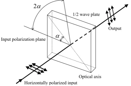
B. 1/2 Wave Plate
The 1/2(half) wave plate can be used to rotate the polarization state of a plane polarized light as shown in Fig. 8. Suppose a plane-polarized wave is normally incident on a wave plate, and the plane of polarization is at an angle α with respect to the fast axis, as shown. After passing through the plate, the original plane wave has been rotated through an angle 2α. Therefore, the incident light is horizontally polarized wave at 45 degrees with respect to the axis, the output wave is vibrating vertically.
Input polarization plane
1/2 wave plate
α
2α
Optical axis Horizontally polarized input
Output
Fig. 8 1/2 wave plate
C. 1/4 Wave Plate
A 1/4 wave plate is used to turn plane-polarized light into circularly polarized light and vice versa. We may do this by orienting an incident plane-polarized wave at 45 degrees to the optical axis. As shown in Fig. 9, circularly polarized light may be produced by passing linearly polarized light through a 1/4 wave plate at an angle of 45 degrees to the optic axis of the plate. Moreover, the mirror reverses the direction of circular polarization, and the reflected reversed circularly polarized light is converted back into linearly polarized light by the wave plate. Therefore, when a l/4 wave plate is double passed, i.e., by mirror reflection, it acts as a l/2 wave plate
and rotates the plane of polarization to a certain angle, i.e., 90
degrees, as shown in Fig. 9.
x y
x y Input
Output
Plane-polarized Circularly polarized
1/4 wave plate Reflection screen
[image:3.595.57.278.332.448.2](i.e.Mirror)
Fig. 9 Rotation of polarization axis
LC molecule
Input Output
Alignment layer
Alignment layer
(a) Off state
LC molecule
Input Output
Alignment layer
Alignment layer
[image:3.595.57.285.593.743.2]D. Liquid crystal layer
Fig. 10 is brief illustration of a LC cell (liquid crystal layer). As shown in this figure, the conventional LCD panel consists of two liquid crystal layers, a polarizer and an analyzer. The liquid crystal layer can rotate the direction of polarizations as shown in Fig. 10. The angle of rotation is controlled by the luminance gradation of input video signals as shown in Fig. 11. The authors have developed 3D display system using this polarization control technique by the LCD panel[1][2][3][4]. In this paper, the liquid crystal layer is applied to generating an invisible 2D code.
0 10 20 30 40 50 60 70 80 90 100
50 100 150 200 250
Angle (deg.)
[image:4.595.336.529.109.531.2]Value of luminance gradation
Fig. 11 Characteristics of the polarization
V. INVISIBLE CODE DISPLAY
The printing technology using a special pigment enables us to provide a publication embedded with invisible codes. This technique is useful for developing an interaction system. We want to make good use of invisible codes at an electric display as well as a paper.
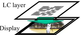
To display visual information and to embed invisible additional information, the display panel needs to hide code symbols so as not to interfere with screen viewing as shown Fig. 12. So we utilize a polarized symbol image to overlap additional information on the visual screen. The polarized light wave has a useful characteristic to generate hidden images. You know you cannot perceive digits of a calculator if a polarizer is removed from an LCD, i.e., it is impossible
for human’s eyes to distinguish characteristics of polarization. In our interaction display system using LCD panels, we utilize characteristics of polarization. As shown in Fig. 13, our proposed display system consists of a conventional LCD panel, an additional liquid crystal (LC) layer and some optical elements.
LC layers can rotate the direction of the polarization axis according to the applied voltage. The LC layer sandwiched between both polarizers displays visual information. This structure functions as an LCD panel. Then this LCD panel emits the polarized light due to the existence of a surface polarizer (it is called an analyzer). Moreover, the overlaid additional LC layer changes the direction of polarization from LCD outputs. This LC layer generates invisible symbol patterns. A 1/4 wave plate is used to turn-polarized light into circularly polarized light and vice versa as shown in Fig. 9. The final LC layer and this 1/4 wave plate output left or right circular polarized light waves. This difference of rotating
direction makes a binary symbol image. As humans cannot perceive differences of polarization, they directly watch only visual images on the viewscreen without perceiving symbol patterns.
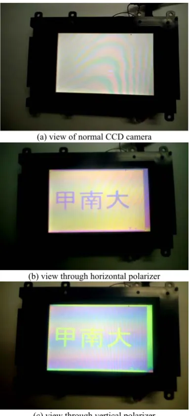
(a) view of normal CCD camera
(b) view through horizontal polarizer
(c) view through vertical polarizer Fig. 12 Invisible display unit
LC layer
LC layer Analyzer
Polarizer 1/4 wave plate
LCD display Human eye
Camera
Fig. 13Principle of generating invisible code
1/4 wave plate LCD display
LC layer
1/4 wave plate Polarizer Through
Blocked
[image:4.595.58.283.201.339.2]At the detection, the polarized symbol pattern images are observable through the 1/4 wave plate and the polarizer because the combination of these optical elements blocks the wave or not as shown in Fig. 14. This enables a camera to detect the invisible code on the display panel. Humans and cameras can perceive the hidden pattern through these optical elements. So the display panels show visual images and invisible symbols simultaneously. Human’s eyes can get only visual information and a code reader finds an only binary symbol pattern.
Using this invisible code, the display system provides all users with visual information and assistance like an audio guide if the user needs a support and it can realize the adaptive interface.
Target objects
Receiver
Receiver
Computer Information data
(Modulated wave)
Computer IP Network Handheld
Terminal
Wireless
[image:5.595.54.281.246.396.2]Email viewer Modulator Laser
Fig. 15 Handheld information query system
VI. OTHER USEFUL USAGES
A. What is information query system
It is easy to get the information about an object with in your reach. But it is troublesome to do the same in case that the object is far away. If someone is around you, you can ask an easy question with a finger pointing; “What is that?” An information query system also realizes this approach using information technologies. The system consists of a laser pointer, transmitter and receiver units for an optical communication. The laser pointer is used for pointing an object. Moreover this laser light is modulated for sending information about user’s identification (ID) codes to identify who asks a question. Each object has a receiver for laser light communication and sends user’s identification to a main computer. After pointing an object, a questioner receives an answer through a wireless information network like an email on the cellular phone.
An outline of a pointing query system is as follows: a component consists of two main blocks; transmitter and receiver units. The transmitter composes a laser pointer and a signal generator for an optical communication. The beam of transmitter unit spreads out more widely than a general laser pointer. In addition, this transmitter can send some information, for example, as identification (ID) codes or data like TV and video remote controller. The spread illumination covers the object you want to select such that you can confirm by your own eyes. Moreover, we attached receivers
close to objects. The receiver catches the ID data of the transmitter which the operator holds in one’s hand. Meanwhile, we utilized the computer IP network for querying the ID database and sending result and information to the transmitter unit. Then the transmitter and receiver units are connected to the computer network. After the receiver gets the ID data, the server computer interprets who asks a question and what is a request, then determines an answer and where to return a response. As the result, the transmitter can receive the answer about a request through the wireless IP network.
B. Handheld information query system
You can directly get the information about the object with in your reach. For example, you can know the price of a product if you bring it close to the price checker in the supermarket. But you can’t always reach a target whenever you want to know. If the target object is far away, it is troublesome for us to approach and to hold it.
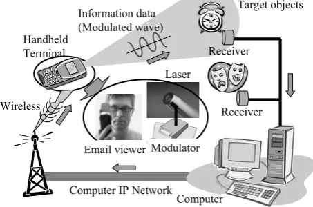
A principal gesture of human is the finger pointing to point the object directly. In case that there is a target at a distance, you may ask someone what that is with finger pointing. The authors devised as this process is mechanized. We developed a pointing system using a laser pointer because the laser illumination can transmit some information by optical communication technology in addition to the pointing. Fig. 15 shows the handheld information query system.
As shown in Fig. 15, a terminal component consists of two main blocks; transmitter and receiver units. The transmitter composes a laser pointer and a signal generator which works as the E/O converter and a laser modulation unit for an optical communication. The beam of transmitter unit spreads out more widely than a general laser pointer. In addition, this transmitter can send some information, for example, as identification (ID) codes or data like TV and video remote controller. The spread illumination covers the object you want to select such that you can confirm by your own eyes.
Meanwhile, receivers are attached close to objects. The receiver catches the ID data of the transmitter which the operator holds in one’s hand. The data received by each receiver is sent to a server computer. We utilized the computer IP network for querying the ID database and sending result and information to the terminal unit. Then the transmitter and receiver units are connected to the computer network.
After the receiver gets the ID data, the server computer interprets who asks a question and what is a request, then determines an answer and where to return a response. The answer is delivered to a questioner as an email through a metal line and a wireless of the computer IP network. As the result, the transmitter can receive the answer about a request through the wireless IP network.
C. Adaptive display system
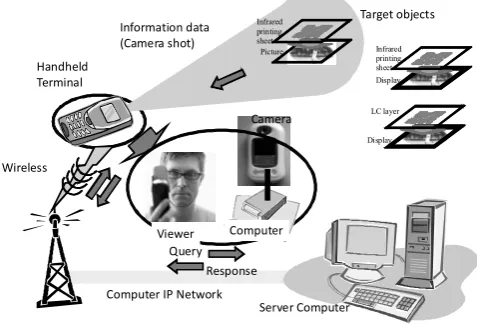
A concept of the above-mentioned information query system is based on a finger pointing, which is one of the gesture on human communication. The authors investigate another contact system instead of the finger pointing. It is a camera vision. The human perceives some vision as information through his/her eye. An adaptive display system realizes this viewing approach using an invisible code displaying technique and information technologies. Fig. 16 shows outline of the adaptive display system. A component of this system consists of a polarization controlled video camera and an invisible code displaying unit. The information is printed on the paper or displayed on the electronic display. The invisible code is overlaid on the information material by an infrared printing or the electronic invisible code display unit. The user shots the information material by a video camera. This special camera can detect invisible codes. After the camera gets the 2D code, this captured code is decoded to string data. For example, using this data, the adaptive display system connects to a server computer through a metal line and a wireless of the computer IP network. The adaptive display system receives additional data from the data server using this connected network. Thus, the display system provides all users with visual information and assistance like an audio guide if the user needs a support using the invisible code.
Target objects
Server Computer Information data
(Camera shot)
Computer IP Network Handheld
Terminal
Wireless
Viewer Computer Camera
Infrared printing sheet
Picture
Query Response
Display Infrared printing sheet
[image:6.595.53.292.392.555.2]Display LC layer
Fig. 16 Adaptive display system
VII. CONCLUSIONS
We developed the invisible code displaying unit which can be only detected by the special video camera. In this paper, we proposed a method to display invisible codes using LCD panels and to detect a polarized symbol image with a conventional CCD camera. This code display systems is useful for working collaborative tasks among users surrounding the table. In addition, we described an additional information query system. This system enables us to get the information about an object wherever the target is. It is easy to get the information about an object with in your reach. But it is troublesome to do the same in case that the object is far away. This adaptive display system can receive the additional information what he/she wants to know via an email as he/she
points a target using a handheld terminal which shots information display system by the built-in camera even if there is a display unit at the distance.
ACKNOWLEDGMENT
This research is partially supported by “Grant-in-Aid for Young Scientists(B)” #20700112 and “Scientific Research (C) (General)” #20500481 from Ministry of Education, Culture, Sports, Science and Technology Japan(MEXT) and also by MEXT ORC (2004-2008).
REFERENCES
[1] K. Sakamoto, H. Nakayama, S. Taneji, “Field-lens Display: Headtracking enables 3D image viewing at any position”, Advances in intelligent IT, Active Media Technology 2006, pp. 277-280, 2006
[2] K. Sakamoto, M. Takaki, M. Nishida, “Parallax Barrier 3D Reflection Display Using Holographic Screen”, Proc. of 12th International Display Workshops, pp.1769-1772, 2005
[3] K. Sakamoto, R. Kimura, M. Takaki, “Elimination of Pseudoscopic Region of Parallax Barrier 3D Display”, Proc. of 11th International Display Workshops, pp. 1497-1498, 2004