Abstract—In radar system, for detecting targets in the strong background clutters, separation of the target requires high range and cross-range resolution in the system. The high range resolution is obtained by utilizing shorter pulses and wideband-FM pulses, therefore, an expensive wideband receiver should be implemented. The alternative system to achieving high range resolution without using wideband receiver is the stepped frequency (SF) radar scheme performed synthetic range profile (SRP) processing. The principle of this radar is that the echoes of stepped frequency pulses are synthesized in the frequency domain to give the shorter pulses in the time domain thorough the IDFT. The SF radar causes some problems due to the Doppler shift when it is applied to detect moving targets. In particular, if the system assumes the fixed synthetic bandwidth and the target velocity, the influence of Doppler shift is greatly affected by the duration of the observation time, which is determined by the frequency step number and the pulse repetition interval.
In this paper, we propose the phase coded stepped frequency (PCSF) radar with using intra-pulse phase coded modulation on each SF pulse. It aims to realize the required synthetic bandwidth by fewer frequency steps. The effectiveness of the PCSF radar performing the Doppler compensation is proved even under low signal-to-noise (SNR) circumstances.
Index Terms—Stepped frequency radar, Phase coded modulation, Synthetic bandwidth processing
I. INTRODUCTION
The received echo signals of radar (e.g. ground search radar) contain both the target and background clutter signals. The background clutter signals, such as reflections by ground, structures, vegetations and so on, interfere with the detection of the targets. Hence it is necessary to separate the target signal from background clutter signals with high spatial resolution as well as range and/or cross-range resolution [1][2]. The aim of our study is focused on the improvement of the range resolution. The straightforward approach for that purpose utilizes short duration pulses and wideband-FM pulses. This narrow pulse system has to realize complicate system architecture, then, it results in higher implementation cost due to a wideband receiver usage. The stepped frequency (SF) radar performed synthetic range-profile (SRP) processing has been proposed to achieve high range resolution without using wideband receiver[3]. The principle
Manuscript received July 22, 2008; revised August 8, 2008.
C. Fukushima is with the School of Integrated Design Engineering, Graduate School of Science and Technology, Keio University, Yokohama, Japan(e-mail:[email protected]).
N. Hamada is with the Department of System Design Engineering, Science and Technology, Keio University, Yokohama, Japan.
of this radar is that the echoes of stepped frequency pulses are synthesized in terms of Fourier transform domain. This enables us to obtain short pulses in the time domain.
In the previous study [4][5], we have evaluated the performance of SF radar in the detection of stationary targets by both the computer simulations and the experiments using actual targets in an actual field. The obtained results verified the effectiveness of SF radar to achieve the range-profile of targets. For the case of moving targets, on the other hand, the Doppler shift causes some problems that degrade both the precision in the detected target location and the peak prominence of target signal after processing. In particular, if the system assumes the fixed synthetic bandwidth and the target velocity, the influence of Doppler shift is greatly affected by the observation time interval, which is determined by the frequency step number and the pulse repetition interval.
The appropriate Doppler compensation is a possible way to avoid the above degradations in SRP processing. The method by Hara et al.[6] gives one way to Doppler compensation. However, exact estimation of the target velocity is a difficult task in the low signal-to-noise (SNR) circumstance. One way to overcome this problem is to shorten the duration in observation to mitigate the effect of target’s moving. This corresponds to reducing the number of pulses. In contrast with reducing the number of pulses, we make the effective bandwidth of each pulse wider to keep the synthesized bandwidth approximately same, because the synthesized bandwidth is determined by the product of the number of SF pulses and the effective bandwidth in each pulse. From the viewpoints of the peak detection, the peak power decreases according to the reduction of the number of pulse N.
The phase coded modulation is used for the conventional SF radar as an intra-pulse modulation to get the signal processing gain for the purpose to make up for the peak power reduction. This kind of system is called the PCSF radar, and studied in [7] and [8]. The system in [7] has to use relatively wider instantaneous received bandwidth, and the study in [8] does not consider the Doppler compensation. We propose the PCSF radar with the Doppler compensation, the bandwidth of which is narrower. The method uses the Doppler compensation based on the estimation by received echo signal. This report discusses an improved method giving high performance in target detection even in low SNR circumstances.
This paper is organized as follows. The range resolution of uncoded pulse radar is presented in Section II. The principle of moving target detection of SF radar and its problems are presented in Section III. The characteristic of intra-pulse phase coded SF radar is presented in Section IV. The results
A Study on Stepped Frequency Radar by Using
Intra-Pulse Phase Coded Modulation
of simulation of proposed and conventional SF with PCSF are given in Section V. The Conclusion is given in Section VI.
II. RANGE RESOLUTION OF PULSE RADAR
The range resolution, denoted by ∆R, of pulse radar is defined as a function of pulse width τ in the time domain as
where c is the speed of light. The required receiver bandwidth BP in the frequency domain and the pulse width τ in the time domain are related by BP = 1/τ, then (1) can be written by
As taking the wider receiver bandwidth BP, the pulse width τ is getting shorter, then the range resolution is improved.
III. STEPPED FREQUENCY RADAR
SF radar is known as a technique to achieve high range resolution profile by using SRP processing. The basic concept of this radar is that the several narrow bandwidth pulses of which center frequency is changed step by step during each pulses are synthesized. The mechanism of SF radar is firstly described and the problems associated to detecting moving target in SF radar are mentioned below.
A. Synthetic Range Profile Processing
The SRP processing of stepped frequency radar consists of the following processes.
1) Transmitting a series of stepped frequency pulses with stepwise time-varying carrier frequency. We denote ∆f as the step frequency width at each pulse.
2) Synthesizing these bandwidths of received pulses in the frequency domain for attaining effective broad bandwidth. 3) Carrying out IDFT for the synthesized bandwidth.
The obtained range resolution by these processes is higher than that given by (2). In the following, we explain the SRP processing by using a simple model and the system architecture of it.
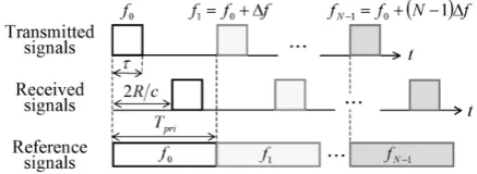
Consider the stationary target model which exists in range R from radar, and R is assumed to satisfy 2R/c < Tpri where Tpri is the pulse repetition interval. Fig.1 shows the SRP processing with frequency step number N. The each pulse is transmitted at different carrier frequency, stepped up by spacing ∆f from the first frequency f0 as shown in Fig.1(a).
Therefore the transmitted nth pulse signal Sn(t) (n=0,1, …,N-1) is expressed as
where A is the amplitude and ϕn is the initial phase of the transmitted pulses. Now, we assume that the transmitted signal is reflected by the stationary target located in range R, then the received signal Un(t)(n=0,1,…,N-1) is expressed by
(a)Transmitted pulses and received pulses in the time domain.
(b)Received pulses in the frequency domain.
[image:2.595.316.535.52.132.2](c)Synthesized bandwidth and resulted range resolution.
Fig. 1. Principle of SF radar by using SRP processing.
where A’ is the amplitude of the received pulses. Consider the reference signal Wn(t) (n=0,1,…,N-1) which has the same frequency and initial phase as Sn(t), but Wn(t) is defined over the interval of tÎ [nTpri, (n+1)Tpri] as follows
Then the video signal Vn(t) (n=0,1,…,N-1) is defined as
where Wn* (t) is the complex conjugate of Wn(t) and A” is A’
multiplied by B. The discrete video signal V(n) (n=0,1, …,N-1), sampled with the same spacing as the transmitted pulse width from (6), is expressed as
Carrying out IDFT for N data of V(n) obtained, the resultant signal of IDFT, P(k) (k=0,1,…,N-1) is given as
2 t c R= D (1) (2) .
2BP c R= D
( )
[
(
(
)
)
]
ï î ï í ì + £ £ + D + = otherwise nT t nT t f n f j A tS pri pri
n n ; 0 ; 2 exp 0 t f p (3) (5) (6)
( )
[
(
(
)
)
]
(
1)
. ; 2 exp 0 pri pri n n T n t nT t f n f j B t W + <£ + D +
= p f
( )
( ) ( )
ï ï î ï ï í ì = = t W t U tVn n n*
(
)
otherwise c R nT t c R nT c R f n f j A pri pri ; 0 , 2 2 ; 2 2 exp " 0 t p + + < £ + úû ù êëé- + D
( )
"exp 2(
0)
2 úû. ù êëé- + D
= c R f n f j A n
V p (7)
( )
( )
(
)
å
å
å
-= -= -= ú û ù ê ë é ÷ ø ö ç èæ -D
÷ ø ö ç è æ-= úû ù êë é úû ù êë
é- + D
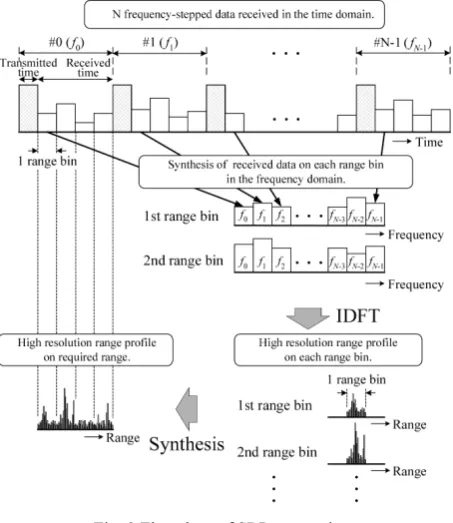
Fig. 2 Flowchart of SRP processing.
and the amplitude of P(k), | P(k) | is given as
| P(k)| takes the maximal value at
and the range R from radar to the target is obtained by
For integer kp, the range resolution ∆R of the SRP processing is given by
where BSF is the synthesized bandwidth of SF radar (=N∆f). This equation means that the ∆R depends on the synthesized bandwidth, namely N∆f. When the ∆f equals BP, the range resolution is improved by the factor of 1/N compared to ∆R in (2) as shown in Fig.1(c). Fig.2 shows the flow of the SRP processing, where the range bin corresponds to the pulse width τ. In practice, the data are integrated at each range bin in the frequency domain. Then IDFT is carried out for N data stepped of each range bin, and we acquire the high range resolution profile on required area.
B. Problem of Moving Target’s Detection
For (4), if the relative velocity of target is not zero (v≠0),
the received echo signal Un(t) (n=0,1,…,N-1) reflected by the moving target is rewritten as
where R0 and v are the initial range of target from radar and
the relative velocity against the radar respectively. In the same sense of (7), sampled version V(n) (n=0,1,…,N-1) of (13) is described as
Because of Doppler shift of the second exponential term in (14), performing SRP processing for N data of V(n) obtained from (14), the detected target range is not correct and also, the target peak is weakened and is diffused. These degradations by Doppler shift depend on the target velocity v and the observation time that is the function of the frequency step number N and the pulse repetition interval Tpri. For reducing the Doppler shift, it is effective to perform SRP processing within less observation time.
IV. INTRA-PULSE PHASE CODED SF RADAR The SF radar realizes broad instantaneous bandwidth for covering the required synthetic bandwidth in less time interval and with fewer frequency steps (lower N), but it is not enough power to detect target after performing SRP processing. In contrast, intra-pulse phase coded SF (PCSF) radar is a technique for reducing the Doppler shift by achieving the required synthetic bandwidth in less time interval, and utilizes the signal gain obtained by pulse compression of intra-pulse phase coded (PC) radar for improving the SNR.
A. Characteristic of Phase Coding
PC radar increases the effective bandwidth by changing the intra-phase of transmitted pulse signal. If the pulse is modulated by code sequence of length M, an uncoded pulse of width τ is divided into M bits of identical duration τC, such that τ=M·τC. Each divided pulse is called subpulse. Then each bit is assigned with a specific code phase value ϕm (m=1,2,…,M), e.g. the phases of 13-element Barker code (M=13) are [0 0 0 0 0 π π 0 0 π 0 π 0]. The range resolution of PC radar denoted by ∆RPC is defined as
where τC is the duration of one bit of code (=τ/M), BPC is the resultant bandwidth of phase coded subpulse of PC radar, and these are related by BPC =1/τC.
B. Range Resolution of PCSF
Combining SF and PC processing, the transmitted PCSF signal can be described as
(8) (9) (11) (12) , 2
2 BSF
c f N c R = D = D . 2N f kp
c R D =
( )
. 2 sin 2 sin " ú û ù ê ë é ÷ ø ö ç èæ - D
ú û ù ê ë é ÷ ø ö ç è
æ - D
= c R f N k N c R f N k N A k P p p
(
)
ú û ù ê ë é ÷ ø ö ç èæ - D
ú û ù ê ë é ÷ ø ö ç è
æ - D
× ú û ù ê ë é -÷ ø ö ç è
æ -D
÷ ø ö ç è æ-= ú û ù ê ë é ÷ ø ö ç è
æ -D
-ú û ù ê ë é ÷ ø ö ç è
æ -D
-÷ ø ö ç è æ-= c R f N k N c R f N k N c R f N k j c R f j N A c R f N k j N c R f N k j c R f j N A 2 sin 2 sin 1 2 exp 2 2 exp " 2 2 exp 1 2 2 exp 1 2 2 exp " 0 0 p p p p p p p , (10) , 2 c R f N
kp= D
, 2 2 PC C PC B c c
R = =
D t (15)
(14)
( )
(
)
(
)
(
)
2 .2 exp 2 2 exp " 2 2 2 exp " 0 0 0 0 0 úû ù êë
é + D
×
úû ù êë
é- + D
= ú û ù ê ë é ÷ ø ö ç è æ -D + -= pri pri nT c v f n f j c R f n f j A nT c v c R f n f j A n V p p p
( )
ï ï ï î ïï ï í ì = t Un(
)
(
)
otherwise c vt R t f n f j A n ; 0 ; 2 2 exp ' 0 0 ú û ù ê ë é ÷÷ ø ö çç èæ ÷+
ø ö ç
è
æ -
-D + f p ÷ ø ö ç è
æ + +
+ < £ ÷ ø ö ç è æ +
+ c t
R nT c v t c R nT c
v pri pri
2 2 1 1 2 2 1
where Cm is the mth code for the nth subpulse, i.e. Cm =exp(jϕm). The PCSF synthesized bandwidth BPCSF depends on PC and SF characteristics, which is expressed as
Hence, the range resolution of PCSF radar is described as (18) , which is the PCSF radar version of (12).
Hence, if the synthesized bandwidth of SF and PCSF radar is the same, the PCSF subpulse bandwidth is larger than that of SF pulse (e.g. BPCSF =M·BSF), the PCSF waveform covers the required synthetic bandwidth using fewer frequency step number. By reducing the observation time interval during a coherent processing, it is effective to mitigate the degradation by target’s moving.
V. SIMULATION RESULTS
In this section, we compare the detection performance of SF with PCSF radar using 13bit-Barker code for intra-pulse phase coded modulation.
A. Results of stationary target and Moving target
The target is assumed as a point reflective target located in the initial range 450m apart from the radar. The parameters of
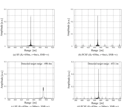
[image:4.595.307.548.260.394.2]simulation are shown in Table I. The amplitude in the figures is the normalized value to the video signal amplitude A” in (6). Fig.3 (a) and (b) show the SRP processing result of SF and PCSF radar respectively, for zero target velocity (v=0), the detected targets are located at the correct range because these are no Doppler shift. Fig.3(c) and (d) show the results of SF and PCSF radar respectively, for the case when the target velocity is not zero (v=300m/s). The detected target ranges of SF and PCSF radar are 490.4m and 453.1m respectively, so the Doppler shift causes incorrect target range estimates as shown in these results. Comparing Fig.3(c) and (d), the target peak of SF broadened due to Doppler shift, though target peak of PCSF is not so deviated. In principle, the range error that corresponds to the target velocity occurs during the pulse width and the subpulse width in SF and PCSF
Table I Parameters of simulation.
System parameter SF (13bit-Barker) PCSF
1st transmitted frequency (f
0) 36GHz 36GHz
Instantaneous received bandwidth 1MHz 13MHz Stepped-frequency width (∆f) 1MHz 13MHz
Step number (N) 512 39
Pulse width (τ) 1μs 1μs
Subpulse width (τC) — 1/13μs Pulse repetition interval (Tpri ) 10μs 10μs
IDFT point number 2048 2048
Synthetic bandwidth (N∆f) 512MHz 507MHz Range resolution (theoretical value) 0.293m 0.296m
(a) SF (R0=450m, v=0m/s, SNR=∞) (b) PCSF (R0=450m, v=0m/s, SNR=∞)
(c) SF (R0=450m, v=300m/s, SNR=∞) (d) PCSF (R0=450m, v=300m/s, SNR=∞)
Fig. 3 Target detection results without Doppler compensation.
( )
[
(
(
(
)
)
)
]
(
)
ï î ï í ì
-+ £ £ -+
+ D + =
otherwise
m nT t m
nT
t f n f j AC t
S pri C pri C
n m
n
; 0
1 1
; 2
exp 0
t t
f p
(16)
.
C PCSF
N f N B
t
= D
= (17)
. 2 2
2 N
c f N
c B
c
R C
PCSF PCSF
t
= D = =
D (18)
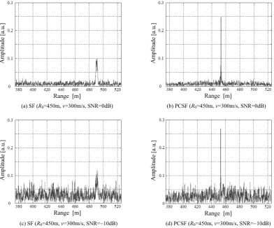
[image:4.595.96.491.413.760.2] [image:4.595.99.276.441.582.2](a) SF (R0=450m, v=300m/s, SNR=0dB) (b) PCSF (R0=450m, v=300m/s, SNR=0dB)
[image:5.595.98.491.50.376.2](c) SF (R0=450m, v=300m/s, SNR=-10dB) (d) PCSF (R0=450m, v=300m/s, SNR=-10dB)
Fig. 4 Target detection results without Doppler compensation with WGN.
respectively. With respect to the reduction of target peak, it is remarkable that SF radar has the lower peak value than that of PCSF. This can be investigated that the smaller number of pulse mitigates the reduction in the peak value. This means the effect of the Doppler shift can be suppressed by reducing the observation time.
Fig.4 shows the SRP processing results in the additive white Gaussian noise (WGN) case. Fig.4 (a) and (b) show the results for the case of SNR=0dB. Then, (c) and (d) show the results for SNR=-10dB, which means target signal is under noise level before signal processing. According to these figures, it is evident that the target detection accuracy of PCSF radar is better than SF radar especially in the low SNR circumstance. However, the incorrect target range is not compensated yet.
B. Effect of Doppler Compensation
This section discusses the target detection performances of SF and PCSF with the compensation for the Doppler. In [6], the Doppler compensation has been proposed using the target velocity vcal estimated by the received data. The compensation is performed using target velocity calculated from the IDFT of phase difference function. The function is the product of the digital video signal V(n) and the α-shifted complex conjugate digital video signal V*(n+α). Here the
sample number of IDFT is N-α. The optimal shift value αopt that the velocity resolution is minimized is N/2.
[image:5.595.99.275.52.190.2]Fig.5 shows the results of SF and PCSF with Doppler compensation for each SNR, where the target velocity is 300m/s inbound and the initial target range is 450m. The simulation parameters are shown in figures. The calculated
Table II Results of calculation for the target velocity Figure System SNR
(dB)
Calculated Velocity vcal (m/s)
Detected Range
(m) 5 - (a) SF ¥ 300.4 450.1 5 - (b) PCSF ¥ 295.9 449.9 5 - (c) SF 0 300.4 450.1 5 - (d) PCSF 0 295.9 449.9 5 - (e) SF -10 329.0 460.6 5 - (f) PCSF -10 309.9 450.3
velocities and detected target ranges are shown in Table II. We can observe precise estimation results. As shown in Fig.5 (a) to (d), compensating Doppler shift, the target is detected at the correct range of target (450m). However, the estimation by the SF for the lower SNR does not give correct range as shown in Fig.5 (e), because it could not precisely compensate Doppler shift due to noise. On the other hand, the results of PCSF at lower SNR show precise range estimation as shown in Fig.5 (f).
VI. CONCLUSION
[image:5.595.314.541.415.514.2](a) SF (R0=450m, v=300m/s, SNR=∞) (b) PCSF (R0=450m, v=300m/s, SNR=∞)
(c) SF (R0=450m, v=300m/s, SNR=0dB) (d) PCSF (R0=450m, v=300m/s, SNR=0dB)
(e) SF (R0=450m, v=300m/s, SNR=-10dB) (f) PCSF (R0=450m, v=300m/s, SNR=-10dB)
Fig.5 Target detection results with using Doppler compensation.
adopted as the intra-pulse modulation to avoid degradation in the peak height.
The simulation results show that the proposed PCSF method suppresses the degradation in target signals sufficiently, with respect to the Doppler shift even in the low SNR circumstances. In addition, it is shown that higher precision in range estimation can be achieved with the Doppler compensation. The precision in the target velocity estimation is not so superior in PCSF radar as in SF radar, because SF uses small number of pulses processed. This would be solved in further research.
REFERENCES [1] B. Edde, Radar, Prentice Hall, New Jersey, 1993.
[2] G. Stimson, Introduction to Airborne Radar, SciTech Publishing, New Jersey, 1998.
[3] D. R. Wehner, High Resolution Radar, 2nd ed., pp.197-237, Artech House, Boston, 1995.
[4] C. Fukushima, and T. Yamaoka, “Range Profile Measurement on Synthetic Bandwidth Radar,” IEICE Trans. Commun.(Japanese Edition), Vol.J89-B, No.6, pp.999-1006, Jun 2006.
[5] C. Fukushima, “Experimental consideration on the synthetic range- profile processing by stepped-frequency radar,” IEEE TENCON2007, pp.1-4, 30 Oct-2 Nov. 2007.
[6] T. Hara, T. Sekiguchi, I. Chiba and S. Wadaka, “Doppler frequency tolerant synthetic bandwidth radar,” IEICE Trans.
Commun.(Japanese Edition), Vol.J89-B, No.7, pp.1131-1140, July 2006.
[7] M. A. Temple, K. L. Sitler, R. A. Raines and J. A. Hughes, ”High range resolution (HRR) improvement using synthetic HRR processing and stepped-frequency polyphase coding,” IEE Proc. Radar Sonar Navig., Vol.151, No.1, pp.41-47, February 2004. [8] Jin Kai, Wang Wei-dong and Wang Dong-Jin, “The Study on a new