Engine Using Different Catalyst
P. V. Walke, Dr. N. V. Deshpande, A.K.Mahalle
ABSTRACT
Catalytic converter with different catalyst for compression ignition engine to reduce pollute gases is chosen for present work. The emphasis is given on hydrocarbon (HC), carbon monoxide (CO) and oxides of nitrogen. The catalytic converter was designed and developed with different catalyst. The pellets are developed as catalyst The pellets are coated with copper oxide (CuO), cerium oxide ( CrO2) and zirconium dioxide (ZrO2 ) . Pellets are held together in a circular housing at two ends of the converter shell. Cylindrical spacer was used in between circular housing containing pellets to vary the distance and to reduce back pressure on the engine. Experiments were carried out on computerized kirloskar single cylinder four stroke (10 B.H.P, 7.4 KW) diesel engine test rig with an eddy current dynamometer. The converter was tested with different catalyst. There is considerable reduction in HC , CO and NOx.
I. INTRODUCTION
Catalytic converter is an exhaust after treatment, emission control device. It is intended to convert harmful combustion byproducts from an engine cylinder into harmless products, by increasing the rate of reactions, with the use of catalytic reaction at comparatively lower temperature levels. A catalyst is an element or compound that promotes a chemical reaction without being affected by the reaction.
The purpose of using catalytic converter in spark ignition and compression ignition engines is same i.e to convert the harmful combustion byproducts into harmless products. But the combustion process of spark ignited gasoline engine and
P. V. Walke Asstt. is a professor of Department of Mechanical Engg., G. H. Raisoni College of Engineering, Nagpur (Email : [email protected])
Dr. N. V. Deshpande is a Professor of Department of Mechanical Engg. Visvesvaraya National Institute of Technology, Nagpur (Email : [email protected])
A.K.Mahalle is an assistent professor of Department of Mechanical Engg., G. H. Raisoni College of Engineering, Nagpur (Email : [email protected])
diesel engine differ considerably. Modern gasoline engines with closed loop emission controls produce exhaust i.e. near chemical stoichiometry and at temperature of 375°C to 850°C. The exhaust contains significant amount of hydrocarbon (HC), carbon monoxide (CO) and oxides of nitrogen (NOx) that must be reduced using catalytic converter. Compression ignition engines burn with lean air-fuel mixtures of less than 20:1 that produce exhaust temperatures of 100 to 400°C. This exhaust contains significant amount of particulate and pollute gases, that may require an after treatment device such as catalytic converter, in order to meet current requirements. To meet the environmental legislations, it is essential to reduce the amount of NOX in the exhaust gases
II. FABRICATION OF CATALYTIC CONVERTER
• Inlet cone was fabricated for converter housing.
Exhaust gases from the engine are admitted through inlet cone
• Outlet cone was fabricated .Eco-friendly exhaust gases come out at this end.
• Cylindrical spacer and two circular housing with provision for putting pellets were fabricated.
• Pellets of different catalytic materials were developed.
• The components were assembled and fitted to engine exhaust manifold.
III. DESIGN CALCULATION
SHAPE OF CATALYTIC CONVERTER
The cylindrical shape was considered due to ease of fabrication, minimum assembly time, rigidity and easier maintenance.
VOLUME OF CATALYTIC CONVERTER
Assuming space velocity (for single cylinder engine) = 30000 hr –1
The space velocity is calculated as under
Volume Converter
rate flow Volume velocity
The converter volume was calculated as Velocity Space rate flow Volume volume
Converter = (2)
( ) hr m 42.63 60 2 / 1500 11 . 0 102 . 0 4 hr. / stroke intake of Number Volume Swept rate flow Volume 3 2 = × × × × = × = π ml 1421 30000 63 . 42 volume converter = = Shell Dimensions
The Shell is the central cylindrical part between the two inlet and outlet cones. This part contains circular discs with coated pellets.
( )
D lVcylinder= × ×
2
4
π (3)
Inlet Cone
The inlet cone is longer than outlet cone to take care of any thermal stresses. One end of the cone is matched with exhaust pipe diameter.
∴
[
( )
( )
]
3 2 2 2 1 21 r r r
r h Cone of
Volume =π× + × +
(4)
Outlet Cone
Outlet cone is smaller in size than inlet cone as temperature of the exhaust gases is reduced while flowing through the inlet cone and shell. Thus there is no possibility of thermal stresses.
∴
[
( )
( )
]
3 2 2 2 1 21 r r r
r h Cone of
Volume =π× + × +
(5)
Spacer
Cylindrical spacer is located in between the circular housing containing pellets to reduce back pressure and restricting the movement of circular
Catalysts
The catalysts used are
• copper oxide (CuO) pellets
• cerium oxide (CrO2) pellets.
• zirconium dioxide (ZrO2) pellets.
Insulating Material
For the proper chemical reaction within the converter, the exhaust gas temperature should be 300-400°C. To maintain this temperature insulation is provided over the shell, inlet and outlet cones. Asbestos was used as insulation material.
IV. EXPERIMENTAL SETUP
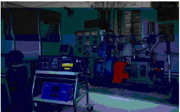
Computerized single cylinder four strokes diesel engine with eddy current dynamometer set was used in experimentation. It is water cooled, vertical four stroke compression ignition engine. Other equipments used are as under.
• AVL smoke meter for smoke density measurement
• AVL five gas analyzer for measurement of HC, CO and NOx.
Engine specification
• Compression ratio – 17.5 : 1
• Bore – 102 mm
• Stroke – 116 mm
• Power – 10 BHP (7.4 KW)
• Arm Length – 180 mm
• Maximum torque – 32 N-m
• RPM – 1500
EXPERIMENTATION
The observations for various trials are as under:
• Smoke opacity of diesel exhaust at every operating condition was measured with AVL make smoke meter.
• CO, HC and NOx: were measured with the AVL make five gas analyzer.
• Temperature was measured with the help of thermocouples fitted in the exhaust system.
• Engine back pressure was measured with the help of manometer.
• Air flow and fuel flow were directly measured by digital indicators.
The trials were conducted on computerized single cylinder 4-stroke kirloskar diesel engine with eddy current dynamometer to evaluate the performance of catalytic converter using cerium oxide, copper oxide and zirconium dioxide. The trial were conducted by considering the maximum allowable back pressure within permissible limit i.e. 50 mm of H2O. The parameters were compared with converter and without converter, for same engine output conditions. The speed of engine was kept constant at 1500 rpm.
V. RESULTS AND DISCUSSION
Figure I shows variation in HC. Considerable reduction in HC emission was observed by using catalytic converter. Catalysts using zirconium dioxide shows reduction of HC emissions from 90 ppm to 39.2 ppm.
Figure II shows variation in CO. Considerable reduction
in CO emission was observed for all catalysts.
Figure III shows variation in NOx emission. By using zirconium dioxide + cerium oxide, shows reduction of NOx emissions from 160 ppm vol.to 120 ppm vol.
[image:3.595.315.540.104.295.2]
Figure IV shows variations in smoke opacity . By using catalytic converter the concentration of smoke opacity increases, and this was due to exhaust gases.
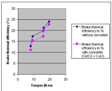
Figure V shows variation in brake thermal efficiency. Negligible reduction was observed by using catalytic converter.
Figure VI shows variation in brake thermal efficiency due to back pressure . Insignificant variation in brake thermal efficiency was observed with increase in back pressure due to converter.
0 20 40 60 80 100
H
C
i
n
ppm
1) Without converter
2) Converter with copper oxide catalyst
3) Converter with cerium oxide catalyst
4) Converter with zirconium dioxide catalyst,
Figure I: Comparison of HC emission (constant rpm 1500)
0.1 0.105 0.11 0.115 0.12 0.125 0.13
CO in %
1) Without converter
2) Converter with copper oxide catalyst
3) Converter with cerium oxide catalyst
4) Converter with zirconium dioxide catalyst
[image:3.595.316.543.394.666.2]
0 50 100 150 200
NO
x (
ppm vol
.)
1) Without converter
2) Converter with copper oxide catalyst
3) Converter with cerium oxide catalyst
4) Converter with zirconium dioxide catalyst
5) Converter zirconium dioxide +
cerium oxide catalyst
Figure III: Comparison of NOx emission (constant rpm 1500)
44 46 48 50 52 54 56 58 60
Smo
ke o
p
acity (%)
1) Without converter
2) Converter with copper oxide catalyst
3) Converter with cerium oxide catalyst
4) Converter with zirconium dioxide catalyst
[image:4.595.62.293.120.713.2]5) Converter zirconium dioxide + cerium oxide catalyst
[image:4.595.318.537.126.304.2] [image:4.595.62.291.401.698.2]Figure IV: Comparison of smoke opacity (constant rpm 1500)
Figure V: Variation in brake thermal efficiency vs. torque (constant rpm 1500)
0 5 10 15 20 25 30 35
1 2 3 4
Br
ake th
er
mal efficien
cy (%) Back
p
ressu
re
(cm o
f H2O) brake thermal
efficiency (%) Back pressure (cm of H2O)
1) Without converter
2) Converter with copper oxide catalyst
3) Converter with cerium oxide catalyst
4) Converter with zirconium dioxide catalyst
Figure VII: Catalytic converter, catalysts coated pellets and circular housing.
VI. CONCLUSION
The conclusions from the investigation are summarized as under:
1. Zirconium dioxide catalysts reduces HC emission .
2. All three catalysts (zirconium dioxide, cerium oxide and copper oxide ) reduce CO emissions. 3. The catalyst (zirconium dioxide + cerium
oxide), reduce NOx emission
4. Brake thermal efficiency decreases with. Catalytic converter. However, this decrease is marginal and it can be accepted in view of benefits on environment and health of human being in particular.
References
[1] Heywood J. B., “Internal combustion engine fundamentals”, McGraw Hill Book Company, 1992
[2] Prof. Walke P.V., GHRCE Nagpur, Dr. Deshpande N.V. ,Professor,V.N.I.T,Nagpur , “Performance and emission characteristics of Diesel Engine using catalyst with exhaust gas
recirculation.” Proceedings of ASME,Mechanical engineering congress and
exposition, November 05-10, 2006, Chicago, Illinois, paper No. IMECE2006-14484
[3] Bouglas J. Ball and Robert G. Stack, “Catalyst for diesel powered vehicles”, A.C. Rochester Division if G.M. Flint, mI-48556, U.S.A., A1991 Elsevier Science publishers B.V. Amsterdam.
[4] Muramatsu G., Furuyama A. Abe M. and Yoshida K. Riken Corp., “Catalytic reduction of NOx in diesel exhaust”, 930135.
[5] Engler B., Koberstein E., Linger D., “The influence of three-way Catalyst parameters on secondary emission”, Crucq (Editor), “Catalysis and Automotive pollution control II” © Elservier science Publishers B.V. Amsterdam, 1991.
[6] Blakeman Philip G., Chiffey Andrew F., “Development in Diesel Emission After Treatment Technology”, SAE Paper 2003-01-3753 (2003).
[7] Egnel R., “The Influence of EGR on Heat Release rate and No formation in DI Diesel Engine”, SAE Paper 2000-0101807.
[8] Itoyama H. Uchida, Hiromichi M., “A study of an EGR Control system for Diesel Engines based on an Intake/Exhaust system model”, SAE – 970621.
Figure VIII : Computerized single cylinder four stroke diesel
[image:6.595.101.439.398.617.2]engine with eddy current dynamometer, AVL Five gas analyzer and smoke meter.