Enhancing layered enterprise architecture development
through conceptual structures
POLOVINA, Simon <http://orcid.org/0000-0003-2961-6207>, VON ROSING,
Mark, LAURIER, Wim and ETZEL, Georg
Available from Sheffield Hallam University Research Archive (SHURA) at:
http://shura.shu.ac.uk/24239/
This document is the author deposited version. You are advised to consult the
publisher's version if you wish to cite from it.
Published version
POLOVINA, Simon, VON ROSING, Mark, LAURIER, Wim and ETZEL, Georg
(2019). Enhancing layered enterprise architecture development through conceptual
structures. In: ENDRES, Dominik, ALAM, Mehwish and ŞOTROPA, Diana, (eds.)
Graph-based representation and reasoning: 24th International Conference on
Conceptual Structures, ICCS 2019, Marburg, Germany, July 1–4, 2019, proceedings.
Lecture Notes in Computer Science, 11530 . Cham, Springer.
Copyright and re-use policy
See
http://shura.shu.ac.uk/information.html
Sheffield Hallam University Research Archive
Enhancing Layered Enterprise Architecture
Development through Conceptual Structures
Simon Polovina1, Mark von Rosing2, Wim Laurier3 and Georg Etzel4
1
Conceptual Structures Research Group, Communication and Computing Research Centre & Department of Computing, Sheffield Hallam University, Sheffield, UK
2 Global University Alliance, Chateau Du Grand Perray, La Bruere Sur Loir, France 3
Universit´e Saint-Louis – Bruxelles, Belgium
4 LEADing Practice ApS, 86157 Augsburg, Germany [email protected], [email protected],
[email protected], [email protected]
Abstract. Enterprise Architecture (EA) enables organisations to align their information technology with their business needs. Layered EA De-velopment (LEAD) enhances EA by using meta-models made up of layered meta-objects, interconnected by semantic relations. Organisa-tions can use these meta-models to benefit from a novel, ontology-based, object-oriented way of EA thinking and working. Furthermore, the meta-models are directed graphs that can be read linearly from a Top Down View (TDV) or a Bottom Up View (BUV) perspective. Conceptual Structures through CG-FCA (where CG refers to Conceptual Graph andFCAto Formal Concept Analysis) is thus used to traverse the TDV and BUV directions using the LEAD Industry 4.0 meta-model as an il-lustration. The motivation forCG-FCA is stated. It is discovered that
CG-FCA: a) identifies any unwanted cycles in the ‘top-down’ or ‘bottom-up’ directions, and b) conveniently arranges the many pathways by which the meta-models can be traversed and understood in a Formal Concept Lattice. Through the LEAD meta-model exemplar, the wider appeal of
CG-FCAand directed graphs are also identified.
1
Introduction
Enterprise Architecture (EA) enables organisations to align their information technology with their business needs. In common with certain other Enterprise Architecture (EA) frameworks, models or approaches (e.g. The Open Group Ar-chitecture Framework, TOGAF [6]), Layered Enterprise ArAr-chitecture Develop-ment (LEAD) has developed meta-models that formally depict best current and future business practices as reusable patterns by organisations. By reusing what is already known, organisations avoid reinventing the wheel thus freeing them to concentrate their limited resources on best serving their clients rather than in-curring unnecessary costs and risks. LEAD is a layered EA because it articulates an organisation’s business, information and technology domains according to 87 elements or ‘meta-objects’ in layers and sub-layers1. The 87 meta-objects are
1
interconnected by semantic relations that collectively make up the meta-models provided by LEAD. Through the LEAD practitioners’ body LEADing Practice and the non-profit Global University Alliance (GUA) academic and research community, organisations and academia benefit from a novel, ontology-based and object-oriented way of EA thinking and working [11, 14].
The rest of the paper is structured as follows. Section 2 introduces the LEAD meta-model and how it was formalised and analysed. Section 3—the method section—explains why CG-FCA (where CG refers to Conceptual Graph and FCA to Formal Concept Analysis) was applied to this meta-model. Section 4 shows the resulting Formal Concept Lattice (FCL). Section 5 provides further discussion about the cycles that may emerge during this process, as well as related and future research. Section 6 concludes the paper.
2
The Meta-model Diagram
[image:3.612.135.482.426.571.2]Like TOGAF and others, the LEAD meta-models are visualised as UML Class Diagrams with one compartment for the meta-object’s name as the class type with two-way directed associations called semantic relations that run to-and-from each meta-object. As such, each semantic relation describes how a given meta-object can be viewed from its associated meta-object, and vice versa. The meta-models are thus two-way directed graphs that can be read linearly from top to bottom (i.e. ‘top-down’) or bottom to top (‘bottom-up’) depending on the meta-object’s position in the meta-model.
Fig. 1: LEAD Industry 4.0 meta-model, illustrated with levels
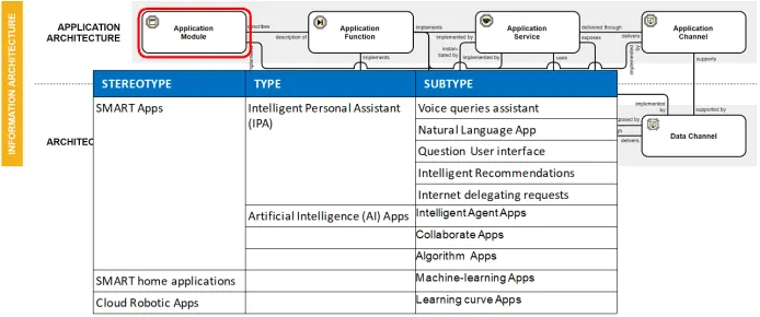
consists of a layered meta-model composed of a subset of the 87 meta-objects i.e. 33 meta-objects, and 54 semantic relations. Its layers are: Business Architecture, Information Architecture (shown in Fig. 1) and Technology Architecture.
Each layer has a sub-layer e.g. Information Architecture has ‘Application Architecture’ as its sub-layer. Fig. 1 illustrates this layer and sub-layer. It also shows the levels within the layers of the Industry 4.0 meta-model. These levels (as opposed to layers) are stereotype (level 2), type (level 3), and sub-type (level 4). As these lower levels are subclasses or instances of level 1—the meta-object— they can substitute the meta-object and inherit its semantic relations with other meta-objects. Similar substitutions for populating a model from a meta-model have also been demonstrated in CGs [5]. They follow Liskov’s substitution prin-ciple, thereby bringing the polymorphism that object-orientation offers into the meta-model [8].
The focus of this paper is however on the meta-objects (level 1). Conse-quently, the levels in Fig. 1 were included to illustrate how a meta-object might be populated with objects having more specific content. These subclasses and instances are nonetheless dependent on the meta-object (again after Liskov). It is also important that the meta-model is useful, after Box’s remark that “All Models are Wrong, but Some are Useful” [4]. The aim therefore is for the meta-models to be as expressive and useful as possible rather than perfect. They must still avoid being useless or harmful; inaccuracies may have an adverse impact on the organisation as it populates the model with its subclasses or instances of the meta-objects.
3
Analysing the Meta-Model with CG-FCA
CG-FCA brings to the meta-models the mathematical rigour of FCA [3, 12]. A formal concept in FCA is the result of when certain conditions are met in a formal context:
– A formal context is a ternary relation K= (G,M,I), where G is a set of objects, M is a set of attributes, and I ⊆G×M is a binary (true/false) relation that expresses which objects have which attributes.
– A pair (A,B) is a formal concept of a context (G,M,I) provided thatA⊆G,
B⊆M,A0=B, andB0=A, whereA0 ={m∈M |gImfor allg∈A}, and B0={g ∈G|gIm for allm∈B}.
– (A,B) is thus a formal concept precisely when:
• every object inAhas every attribute inB,
• for every object inG that is not inA, there is some attribute in B that the object does not have,
• for every attribute in M that is not inB, there is some object in A that does not have that attribute.
FCA to be applied to the meta-models through theCGtoFCAternary relation-to-binary relation algorithm and its implementation in the CG-FCA software2.
The motivation for this approach will be elaborated as part of the related re-search discussion in subsection 5.2 of section 5 below. Whereas CG-FCA for-merly converted Conceptual Graphs (CGs) only, it can now read 3-column CSV files thereby (primitively) allowing any form of ternary relations to benefit from CG-FCA [3].
3.1 Discovering Pathways
The purpose of stating the meta-model as directed graphs is to discover the pathways from one meta-object to all other meta-objects that it is semantically associated with through the semantic relations. These semantic associations can both be direct (i.e. Meta-Object, semantic relation, Meta-Object) and indirect (i.e.Meta-Object, semantic relation, ...3, semantic relation, Meta-Object). These
pathways allow us to define a meta-object’sview, which is the set of all meta-objects that can be associated with the meta-object defining the view through direct and indirect associations in a single direction (i.e. top-down or bottom-up). Each view represents how that meta-object views itself in relation to its asso-ciated meta-objects. For example, reading from top to bottom:Data Component, implemented by, Application Function states that from the Data Compo-nent’s point of view it sees itself as being implemented by an Application Func-tion4, and reading from bottom-to-top,Application Function, implements, Data Component states the association from Application Function’s point of view (i.e. an Application Function views itself as implementing a Data Compo-nent). The two views are thus complementary to each other. For convenience, we shall refer to these linear directions as the a) Top-Down View (TDV) and b) Bottom-Up View (BUV).
3.2 Managing Cycles
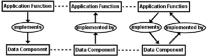
However if we navigate from both points of view (i.e. TDV and BUV), then we end up in an immediate cycle whereby the meta-objects cycle with each other rather than traverse the whole meta-model linearly. Fig. 2 illustrates the evident cycle for theApplication Function, implements, Data Component, implemented by, Application Functionexample above. As the dotted line in CGs represent co-referent links thereby meaning that the CG concepts (meta-objects) are identical, Fig. 2 shows the actual CG join on the right-hand CG
2 https://sourceforge.net/projects/cgfca/ 3
These dots can either be replaced a Meta-Object or by a chain of any number of
Meta-Object, semantic relation, Meta-Object triples
4
hence the cycle. Consequently, we must navigate from one view being either TDV or BUV,notboth. Incidentally, we call these ‘top-down’ or ‘bottom-up’ as a convenient term to suggest the initial direction of the view traversal. Typically therefore, going ‘top-down’ (TDV) suggests choosing a starting (or source) meta-object that is somehow seen as higher up in the layers (and vice versa for ‘bottom-up’, BUV). This can easily be subjective, as for example with meta-objects next to each other in the same sub-layer which one of them may be the ‘higher’ ? Furthermore, semantic relations that initially start top-down may turn bottom-up as associated meta-objects are navigated in turn. Our reference to top-down or bottom-up is thus a working definition rather than a perfect one, especially for our models to be useful [4].
Fig. 2: CG Views of Data Component and Application Function
3.3 Applying CG-FCA to the exemplar
Going back to the complete version of Fig. 1 as our industrial exemplar of a meta-model with bidirectional associations, CG-FCA is applied to the ternary relations that make up directed graphs thereby turning them into binary re-lations. The meta-object → semantic relation → meta-object ternary relations that make up the complete version of Fig. 1 are saved in a simple CSV file. This file has as its the first column the (source) meta-object, the second the seman-tic relations, and third the (target) meta-object. For example, reading from top to bottom: Data Component, implemented by, Application Function and from bottom to top:Application Function, implements, Data Component. These ternary relations are amongst the ternary relations that, when joined together, make up the complete version of Fig. 1 and, incidentally, reveal the two-way nature of the semantic relations. Each ternary relation forms a new row in the CSV file. All the ternary relations can then in turn be read by the CG-FCA software converting it to meta-objectasemantic relation → meta-object binary relations. For example the ternary relation: Data Component,
implemented by, Application Functionbecomes the binary:Data Componentaimplemented by→ Application Function. The binary relations are subsequently re-joined
applying CG-FCA to the meta-model allowed for identifying any bi-directional relation cycles between two related meta-objects with unwanted cycles.
3.4 More Cycles
All legitimate cycles originating in the bidirectional nature of the associations should be eliminated by separating the directed graphs into TDV and BUV. CG-FCA still however identifies the following cycles in the complete version of Fig. 1’s TDV and BUV respectively:
TDV
Cycle: Business Service - contributes value in support of - Mission - threatened by - Risk - mitigated by - Security - protects - Business Service
Cycle: Business Service - contributes value in support of - Mission - threatened by - Risk - mitigated by - Security - protects - Location - delivers - Business Service
Cycle: Business Service - contributes value in support of - Mission - threatened by - Risk - influences the design of - Business Channel - serves - Business Service
BUV
Cycle: Mission - supported by - Business Service - protected by - Security - mitigates - Risk - threatens - Mission
Cycle: Mission - supported by - Business Service - delivered at - Location - protected by - Security - mitigates - Risk - threatens - Mission
Cycle: Mission - supported by - Business Service - served by - Business Channel - design influenced by - Risk - threatens - Mission
At this point it is worth reiterating that putting EA meta-models together is a manual activity. The risk of the human modeller making mistakes in producing the meta-model is always present. This likelihood was demonstrated for CG-based models so could equally happen to the LEAD meta-model [3]. Recognising this possibility is one of the key motivators for using CG-FCA’s automated capacities to capture manual errors in the LEAD meta-models.
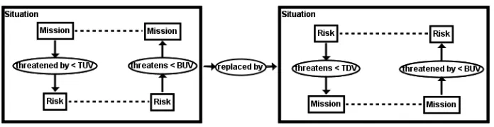
The cycles above highlight this issue: The TDV and BUV semantic relations between theMissionandRiskmeta-objects could be under the wrong view and simply need to be swapped over. The modeller (e.g. an Enterprise Architect or Business Analyst) could also have chosen other candidates to swap instead, such as the semantic relations betweenBusiness ServiceandMissionbut from the feedback given by CG-FCA’s report decides onMissionandRisk. In practice the modeller may want to explore the other candidates, further informed by the FCL in section 4. CG-FCA and the FCL thus augments the expertise of the modeller through these subsequent iterations towards a more useful meta-model [4].
Fig. 3: CG changing the order of TDV and BUV semantic relations
corresponding BUV‘threatens’ semantic relation is changed to a TDV. Fig. 3 formally describes this swap in CGs by re-depicting ‘threatens’ as a TDV sub-relation, ‘threatened by’ as a BUV sub-relation and vice versa. When CG-FCA is re-run on the corrected TDV of the meta-model and the corrected BUV of the meta-model, the cycles disappear.
Another Cycle: Well, almost. In the BUV report there were other cycles:
Cycle: Platform Device - hosts - Application Service - specializes as - Platform Service - instantiates - Platform Device
Cycle: Platform Service - hosts - Application Service - specializes as - Platform Service
As there are no ‘complementary’ cycles in the TDV report that would sug-gest a TDV would need to be swapped with a BUV, this finding was suspect. It emerges that there was a classic human error—i.e. a typo—in the CSV file i.e.: Application Service, specializes, Platform Service. By correcting it to: Infrastructure Service, specializes as, Platform Service those remaining rogue cycles were gone. We are of the view that legitimate cycles in the meta-models though conceivable would be exceptional. They would always require special investigation rather than simply accepting them, as the later subsection 5.1 in section 5 further highlights.
4
Visualising the Complex Pathways in the FCL
We now explore and interpret the FCL from the FCA formal context that was generated by CG-FCA as first described in section 3. To do so, the FCA for-mal context file (.cxt) file produced by CG-FCA is read into Concept Explorer (https://sourceforge.net/projects/conexp/) from which the FCL can be gener-ated. Fig. 4 visualises the result for the TDV of the meta-model. It is one of the linear views; there is also an FCL for the BUV view going in the opposite direction but that is not shown due to space limitations in this paper. However as it is complementary to the TDV (i.e. simply going in the other direction), we can refer to the TDV FCL for demonstrating the BUV FCL as well5.
5
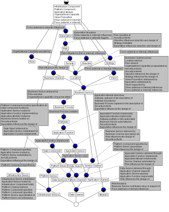
Fig. 4 formalises the UML-based LEAD Industry 4.0 meta-model diagram (of which Fig. 1 is an extract) as a TDV lattice with one formal concept at the top, called the top-most concept and one formal concept as the bottom, called thebottom-most concept. The top-most concept has theInfrastructure
Component,Platform Component,Application Module,Organisational Capability,
Value Proposition,DriverandForcemeta-objects as part of its extent. Traversing down the lattice, the meta-objects relative dependencies are re-vealed. For example,Business Process, which is highlighted in Fig. 5. All the meta-objects in the pathways below the formal concept for the meta-object
Business Process are dependent on it. They are said to be in the extent of the Business Process meta-object. The bottom-most formal concept (at the very bottom of the lattice) has no meta-objects attached to it (i.e. an empty extent).
We can also refer to theintent of a formal concept, based on the attributes of the formal context that was set out in the definition of a formal concept at the beginning of section 3 earlier. (The extent refers to the objects in that definition.) For example the intent of the Business Process meta-object are
all the attributesabove it in the lattice. Hence, the Business Process meta-object depends on the entire meta-objectasemantic relation set of attributes above it. The dimmed component parts in Fig. 5 show those meta-objects and semantic relations that are not in the extent and intent of Business Process. The top-most formal concept has no attributes attached to it (i.e. an empty intent).
All in all by elucidating the pathways, intents and extents the FCL elicits information that: a) is not evident in the UML-based meta-model diagram, b) empowers our understanding of the meta-models and their usefulness, and c) empowers the organisation’s EA through this deeper understanding.
5
Discussion
5.1 Cycles to the Same Meta-Object
Returning to cycles, the semantic relation‘composed of or contained within’
isn’t in the Industry 4.0 meta-model illustration. It does however appear in an-other LEAD meta-model from which this semantic relation is taken. It is explic-itly referred to here as it reveals another form of cycle to which this semantic relation is applied—i.e. one than can point to the same meta-object. In fact, although they have the same meta-object name they aren’t the same instance. They are different business processes6. In CGs this distinction is conveniently
made. Fig. 6 shows this directed ternary relation (view) in CGs, which are based on existential logic that assumes a different referent (instance) unless told other-wise [10]. In CGs to make them the same we have to express them as having the same referent—i.e. co-referent—as illustrated by the variable ‘*a’ in Fig. 7’s
6
CG7. The onus is thus to override the default behaviour of CGs, thereby feeding
back to us to check cycles rather than accept them at the outset.
[image:12.612.133.477.153.508.2]Fig. 6: CG of Business Process
Fig. 7: CG of Business Process that is a Cycle
[image:12.612.139.479.337.475.2](a) No Cycle (b) Cycle
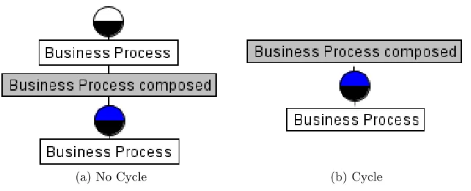
Fig. 8: FCL for Business Process
Fig. 8 highlights how Fig. 6 and 7 are thereby respectively displayed as a FCL8. In an FCL, the circles are the formal concepts. Notably, in the cycle FCL it doesn’t point to another formal concept—i.e. the second Business Process. Rather, CG-FCA expresses the cycle by simply denoting it in the same formal concept. (The semantic relation in the Fig. is shortened from‘composed of or contained within’ to‘composed’for convenience.)
7
Equivalent to the dotted lines denoting co-referents in Figs. 2 and 3.
8 The CGs in this paper were drawn in CharGer (http://charger.sourceforge.net/)
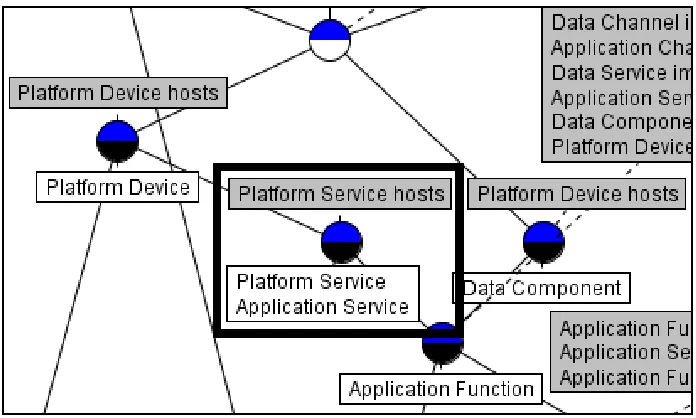
For comparison, to show cycles generally in an FCL from CG-FCA the Fig. 9 shows an extract from a larger FCL with the earlier ternary relation that was de-scribed under ‘Another Cycle:’ in 3.4 of section 3—i.e.Application Service, specializes, Platform Servicebefore it was corrected to:Infrastructure Service, specializes as, Platform Service. It causedPlatform Service
[image:13.612.134.482.208.417.2]to have a cycle that, in this case, was unwanted due to it being a typo.
Fig. 9: CG of Business Process that is a Cycle
5.2 Related research
Earlier we remarked on the motivation forCGtoFCAand CG-FCA. Interrelating CGs and FCA has been a subject of much interest e.g. [9].CGtoFCAarose from Wille’s (and others’) long-standing work on Concept Graphs, and identifying certain shortcomings with Concept Graphs—which Wille distinguished from CG (ConceptualGraphs)—and how they are overcome withCGtoFCA[2,15]. To test its value, CGtoFCAwas implemented in computer software i.e. CG-FCA9 and
its use and benefits published (e.g. [3, 5, 11]).
Similar work was also investigated. Relational Concept Analysis (RCA) ex-plores the attributes found in three compartment UML class diagrams [13].
CGtoFCA however works with single component UML class diagrams where the class name (the meta-object in our case) alone is of interest. This also re-flects that CGtoFCA is more in-keeping with Concept Graphs, from which it
9
derives. The approach applied (in our case to cycles) in subsection 3.4 of sec-tion 3 also touches upon similar work on ontological patterns, anti-patterns and pattern languages for conceptual modelling [7].
5.3 Future research
In our ongoing research, we need to understand what else FCA (through CG-FCA and the FCL) may be telling us. We are in the process of streamlining the process by integrating CG-FCA and the FCL into the Enterprise Modelling toolEnterprise Plus(E+, www.enterpriseplus.tools). Whereas we only remained with the modeller’s initial choices (e.g. in rectifying the unintended cycles), such a streamlined process would allow the efficient explorations of alternatives only indicated in this paper.
Another area of interest is whether the bottom-most formal concept should have its own object. In previous work, populating this formal concept with a meta-object was presented as pertinent to the validity of the meta-model [11]. But as we are currently evaluating the validity of such a claim, that assertion is not made in this paper.
The information gathered by CG-FCA and the FCL of the meta-model com-plements lucidly the UML-based meta-model diagram, serving our present pur-poses. There may however be even more lucid ways of visualising the CG-FCA results. The validity of our approach may spur others to research such visuali-sations. As one alternative, we are evaluating formal concept trees [1]. Given its proximity toCGtoFCA, we also maintain an interest in RCA and to explore it in more depth.
As CG-FCA can be applied to any directed graph beyond the meta-models that we’ve described here, there is potentially a wider remit for its use in the real-world. Previously it was applied to Conceptual Graphs (CGs), and now to single compartment UML class diagrams with directed associations. RDF, RDF(S), OWL are examples of future candidates. Further research in these and other hitherto unidentified areas would be of interest. Meanwhile our work remains focussed in LEAD and the usefulness of EA meta-models for organisations and their clients, given there is more to discover in this focussed area of our research.
6
Conclusion
References
1. Simon Andrews and Laurence Hirsch. A Tool for Creating and Visualising Formal Concept Trees. InCEUR Workshop Proceedings, volume 1637, pages 1–9, 2016. 2. Simon Andrews and Simon Polovina. A Mapping from Conceptual Graphs to
For-mal Concept Analysis. InLecture Notes in Computer Science (including subseries Lecture Notes in Artificial Intelligence and Lecture Notes in Bioinformatics), vol-ume 6828 LNAI, pages 63–76, 2011.
3. Simon Andrews and Simon Polovina. Exploring, Reasoning with and Validating Directed Graphs by applying Formal Concept Analysis to Conceptual Graphs. In
Lecture Notes in Computer Science (including subseries Lecture Notes in Artificial Intelligence and Lecture Notes in Bioinformatics), pages 3–28. Springer, 2017. 4. George EP Box and Norman R Draper. Empirical model-building and response
surfaces. John Wiley & Sons, 1987.
5. Jamie Caine and Simon Polovina. From Enterprise Concepts to Formal Concepts: A University Case Study. In Lecture Notes in Computer Science (including sub-series Lecture Notes in Artificial Intelligence and Lecture Notes in Bioinformatics), pages 84–96. Springer, 2018.
6. The Open Group. 30. Content Metamodel, 2018. http://pubs.opengroup.org/architecture/togaf92-doc/arch/chap30.html.
7. Giancarlo Guizzardi. Ontological Patterns, Anti-Patterns and Pattern Languages for Next-Generation Conceptual Modeling. InER, 2014.
8. Barbara H. Liskov and Jeannette M. Wing. A Behavioral Notion of Subtyping.
ACM Trans. Program. Lang. Syst., 16(6):1811–1841, November 1994.
9. Guy Mineau, Gerd Stumme, and Rudolf Wille. Conceptual structures represented by conceptual graphs and formal concept analysis. InLecture Notes in Computer Science (including subseries Lecture Notes in Artificial Intelligence and Lecture Notes in Bioinformatics), 1999.
10. Simon Polovina. An Introduction to Conceptual Graphs. In Uta Priss, Simon Polovina, and Richard Hill, editors, Conceptual Structures: Knowledge Architec-tures for Smart Applications, pages 1–14, Berlin, Heidelberg, 2007. Springer Berlin Heidelberg.
11. Simon Polovina and Mark von Rosing. Using Conceptual Structures in Enterprise Architecture to Develop a New Way of Thinking and Working for Organisations. In Peter Chapman, Dominik Endres, and Nathalie Pernelle, editors,Graph-Based Representation and Reasoning, pages 176–190, Cham, 2018. Springer International Publishing.
12. Uta Priss. Formal Concept Analysis in Information Science.Annual Rev. Info. Sci & Technol., 40(1):521–543, December 2006.
13. Mohamed Rouane-Hacene, Marianne Huchard, Amedeo Napoli, and Petko Valtchev. Relational concept analysis: Mining concept lattices from multi-relational data. Annals of Mathematics and Artificial Intelligence, 2013.
14. Mark von Rosing and Wim Laurier. An Introduction to the Business Ontology.
International Journal of Conceptual Structures and Smart Applications (IJCSSA), 3(1):20–41, 2015.