An Integrated Framework for Verifying Multiple
Care Pathways
J. Bowles
∗, M. B. Caminati
∗, S. Cha
†∗
School of Computer Science, University of St Andrews
KY16 9SX St Andrews, United Kingdom
{jkfb|mbc8}@st-andrews.ac.uk
†
Automation and Information Systems, Technical University of Munich
Boltzmannstraße 15, 85748 Garching bei M ¨unchen, Germany
[email protected]
F
Abstract—Common chronic conditions are routinely treated following standardised procedures known asclinical pathways. For patients suffer-ing from two or more chronic conditions, referred to asmultimorbidities, several pathways have to be applied simultaneously. However, since pathways rarely consider the presence of comorbidities, applying several pathways may lead to potentially harmful (medication) conflicts. This paper proposes an automated framework to detect, highlight and resolve conflicts in the treatments used for patients with multimorbidites. We use BPMN as a modelling language for capturing care guidelines. A BPMN model is transformed into an intermediate formal model capturing the possible unfoldings of the pathway. Putting together the constraint solver Z3 and the theorem prover Isabelle, we combine treatment plans and check the correctness of the approach. We illustrate the approach with an example from the medical domain and discuss future work.
1
I
NTRODUCTIONIn healthcare management and practice, as in other domains, clinical and medical procedures are streamlined by adopting standardised guidelines. In particular, treatments for com-mon chronic conditions have been subject to various clinical trials, and the outcomes documented inclinical pathways(CPs) specifying accepted treatment steps, possible alternatives, and recommendations to follow. In Scotland, over half of all people with chronic conditions have two or more conditions simultaneously, also known as multimorbidity [22]. When managing the treatment plans for patients with multimorbid-ity, the problem is how to resolve possible contradictions that may arise when combining several CPs. Usually, a CP does not consider the presence of comorbidities and possible consequences of interactions with other pathways are mostly ignored. There is little information on how to handle conflicts when they arise. Improving the care of patients with multimorbidity is a global concern. In the UK, the National Institute of Health and Care Excellence (NICE) publishes CPs for most well known conditions, including a recent general guidance on multimorbidity1. These guidelines, which underly our work, are given in
1. NICE www.nice.org.uk
a combination of visual diagrams and natural language, and capture the steps and decision points taken in the treatment of a disease. They are essentially process descriptions and, to remove some of the inherent ambiguity in these diagrams, we use BPMN (Business Process Modeling Notation) [8] to describe them. Our contribution in this paper is an integrated formal framework to detect, highlight and resolve conflicts in the treatment of patients with multimorbidity, consisting of: 1)A front-end component, offering an interface to manipulate the information contained in existing CPs as BPMN models (generating JSON output). 2)A formal modelto capture the semantics contained in the structure and annotations of the CPs extracted from the front-end stage. This model should be suitable for expressing multiple CPs and formulating the co-existence of conflicts across pathways. 3)A back-end component, implementing the formal model, and capable of applying it to the particular instances of CPs coming from the front-end. This component applies constructions of the formal model to compute and represent the relevant notions of pathway conflicts. 4) Averification componentto formally verify the back-end (e.g., to validate its correctness wrt specifications, expected behaviour, etc).
We use labelled event structures (LES) [25, 16] for the semantics, a mixture of higher-order logic (HOL, a simply typed, functional language to write code and formal proofs), and SMT-LIB [9] (a standardised first-order logic language to interface with many SAT and satisfiable modulo theory (SMT) solvers) for the back-end. This hybrid implementa-tion allows us to: (i) choose between a HOL computaimplementa-tion (either directly in the theorem prover Isabelle or in one of the functional languages Isabelle can generate) and SMT solvers; (ii) formally verify our back-end using HOL and applying formally proven theorems to it (using Isabelle). To communicate between the front-end and the back-end, we use a straightforward JSON format describing a pathway in terms of its LES semantics. Paper structure: Section 2 describes the front-end and how a BPMN model is converted into a LES. Section 3 shows the back-end concentrating on conflict resolution, illustrated with an example in Section 4.
Section 5 discusses related work, and Section 6 concludes.
2
T
HEF
RONT-
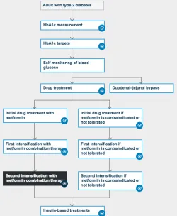
END MODULE [image:2.612.49.299.156.460.2]In practice, CPs are presented in natural language with additional diagrams as shown in Figure 1. When click-ing on individual nodes (as the highlighted one), further information is typically shown in text on the right hand side of the diagram. When reasoning over pathways, these
Fig. 1. Managing blood glucose in adults with type 2 diabetes (NICE)
need to be captured more precisely through domain-specific modelling languages or general-purpose languages such as BPMN or UML Activity Diagrams [7]. Although none of these languages has been proven to be perfectly compatible with clinical pathway process modelling, BPMN is regarded as a promising notation amongst process-oriented modelling languages. Hashemian and Abidi analysed various tech-niques and picked out the main features in a comparison of BPMN with other approaches [12]. Reasons why BPMN attracts attention include its broad acceptance within research and industry, compatibility with various process modelling tools, expressiveness, and simple notation [12, 5]. Thus, it is natural to interface with this format and its intended semantics. The input to our front-end module is a BPMN file in XML format. The module produces a JSON file, in a specific format, describing the corresponding LES used by the back-end component (Section 3). It also produces a graphical representation of the LES and, with feedback from the back-end, can alter such a representation to highlight conflicts. This intermediate LES representation still has to be converted back onto a BPMN model or more suitable visualisation mechanisms for clinicians. Note that this last
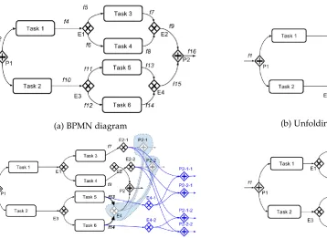
step is outside the scope of the present paper and requires clinical evaluation. For space reasons we omit the BPMN associated to Figure 1. Figure 2 shows a simple BPMN of a process starting with a parallel gateway (splitting the control flow) where the top branch involvesTask 1followed by a choice (exclusive gateway) between Task 3 or Task 4, followed by a merge and by Task 6. Task 2, in the lower branch, is executed in parallel, and the process ends after merging back the branches in the parallel gateway. No conditions are shown here but could be present in an exclusive gateway.
Fig. 2. A simple BPMN example
The front-end module works by extracting knowledge from a given pathway in accordance to a specificontology, and by mapping elements of this ontology into LES concepts. We introduce the ontology in Section 2.1, LES briefly in Section 2.2, and a description of the mapping in Section 2.3.
2.1 BPMN CP Ontology
We follow [12], where ontologies (representing entities, their properties and mutual relationships) are established for both BPMN and clinical pathways. A CP ontology describes a number of specific constructs including branching by a deci-sion, branching for multiple concurrent treatments, activity flows, and so on, as follows. Action_Stepis a clinical ac-tivity to be performed.Decision_Stepdenotes a decision point to determine the next possibleAction_Stepalong the pathway.Route_stepinvolves a possible split/join of the activity flow. This includesBranch_Stepwhen branching the flow so multiple steps can be performed in parallel, and
Synchronization_Step, which joins the flows back into one.Data_elementis an attribute of all classes, containing all the needed domain-specific information.
TheBP M NCP ontology is a subset of the BPMN onto-logy for representing clinical pathways. Each element has common attributesidandname, one incoming flow (except
Start_Event) and one outgoing flow (exceptEnd_Event). An event is an occurrence in the pathway: Start_Event
is the initial event of the pathway, End_Event specifies the end of the pathway, andIntermediate_Eventis any other kind of event, triggered by a certain cause. Activity is a general term for actions done in the process. Every action taken by an actor or participant is an activity. Hence, each
Action_Stepis mapped as an activity.
• Taskrepresents a job to be performed in the process and can be regarded as a unit of work. An atomic
Action_Stepcan be described as aTask.
• Sub-Process is any decomposable activity. The in-ternal details are modelled using Flow Objects [8] of
[image:2.612.329.545.188.263.2]In other words, it contains a valid BPMN diagram inside it. Hence, a modularisedAction_Stepcan be described as aSub-Process.
Gateways are used for depicting diverging flows and con-verging flows. Typically, dicon-verging gateways allow single input and multiple output while converging gateways take multiple inputs and generate a single output.
Exclusive_Gateway controls mutually exclusive flows. Exactly one of the subsequent paths is valid for diverg-ing branches. SoExclusive_Gateway(diverging) appears
where there is a Decision_Step.Exclusive_Gateway
(converging) may appear in case subsequent common el-ements exist for the branches split by the divergence ap-pearing earlier.Parallel_Gatewaycontrols multiple tasks to be completed to proceed. All the branches exiting a divergingParallel_Gatewayare joined by a converging
Parallel_Gatewayat some point, and to proceed on from the converging point the completion of all the incoming branches is a necessary condition. Thus, diverging and
con-vergingParallel_GatewayrepresentBranch_Stepand
Synchronization_Steprespectively.Sequence_Flowis a kind of Connection Object, representing the flow between a pair of other elements above. It is defined usingsourceRef
for indicating its source element andtargetReffor indi-cating its target element. This represents the flow relation between each step in a CP. This is used to provide data de-scription on each element. In [12],Propertyis defined just to deliver or store any generic additional data; even though BPMN provides the possibility of specifying name, type and value of variables inProperty, we need to describe logical and arithmetic general formulas to be passed to the SMT solver. To this end, we chose to store such information in the
Documentationfield, specifying a format for the possible entries, and handling all the details to interface the final user with the back-end: for example, converting the user-friendly infix notation with the Polish notation used in SMT-LIB.
2.2 Labelled event structures (LES)
[image:3.612.314.563.43.202.2]The model we use to capture the interleaving and relation-ships between events in a given BP M NCP is a labelled (prime) event structure [25] or LES for short. What appeals to this model is its simplicity and ability to naturally describe fundamental notions present in such diagrams including sequential, parallel and iterative behaviour (or the unfold-ings thereof) [16, 2]. LES offer simple notions over sets of events to denote event occurrences together with binary relations for expressing causal dependency (causality) and nondeterminism (conflict). Causality implies a (partial) order among event occurrences, while conflict expresses how the occurrence of certain events excludes the occurrence of others (e.g., an event occurring in one branch of a diverging exclusive gateway excludes events in another branch). From the two relations defined on the set of events, a further relation is derived, namely the concurrency relation. Two events are concurrent if and only if they are completely unrelated, i.e., neither related by causality nor by conflict. This relation makes it straightforward to represent parallel BPMN gateways. The formal definition (cf. [16]) is as follows, where traces of execution are maximal configurations.
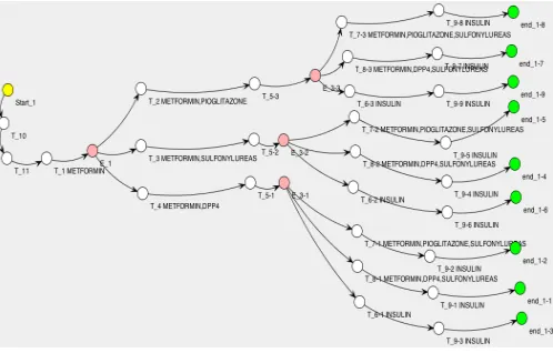
Fig. 3. Type 2 Diabetes LES when metformin is tolerated
Definition 1. Anevent structureis a tripleE= (Ev,→∗,#)
whereEv is a set of events and→∗,#⊆Ev×Evare binary relations calledcausalityandconflict, respectively. Causality →∗ is a partial order. Conflict# is symmet-ric and irreflexive, and propagates over causality, i.e.,
e#e0∧e0 →∗e00
⇒ e#e00 for alle, e0, e00 ∈ Ev. Two
events e, e0 ∈ Ev are concurrent, e co e0 iff ¬(e →∗
e0 ∨e0 →∗ e∨e#e0
).C ⊆ Ev is a configurationiff (1) C is conflict-free:∀e, e0 ∈ C¬(e#e0)and (2)
downward-closed2:e∈Cande0→∗eimplye0∈C.
Event structures are enriched with a labelling functionµ: Ev → 2L that maps each event onto a subset of elements of L. This labelling function is necessary to establish a connection between the semantic model (event structure) and the syntactic model it is describing (hereBP M NCP). A labelled event structure is a pair L = (Ev, µ). The set Lcan be an arbitrary set depending on the domain of use. Here, labels either denote formulas (constraints over integer variables, e.g.,x ≤ 10,y = 5, orHbA1c ≤48) or logical propositions expressing actions or patient conditions (e.g., perform blood test, metformin not tolerated, and so on).
Figure 3 shows the graphical output (using the JUNG framework [21]) of the LES for type 2 diabetes; an internal event is coloured (e.g.,E_1) if it marks the beginning of an alternative, and events show the label (medication) asso-ciated (e.g., metformin and DPP4 forT_4).The figure was obtained by manually converting a NICE pathway into a BPMN model (not shown here for space reasons, but visible at https://sites.google.com/site/tase8prfafyz7v/), and then applying our front-end to translate into an LES.
2.3 From BPMN to LES
We describe theontology mappingbetween BPMN and LES. We use (a subset of) the BPMN ontology workflow elements from [12], mapped to LES as follows:
• Start_Event, End_Event, and Task elements are regarded as events in the event structure.
• Sub-Process is flattened by connecting its
Start_Event and End_Event to predecessor and successor of theSub-Process. Elements in the
Sub-Processare regarded as normal.
• A diverging Exclusive_Gateway is mapped to an
event and all successor elements, which are indi-cated by the outgoing flows of the targeted diverging
Exclusive_Gateway, are defined to be in conflict (#).
• Converging Exclusive_Gateway is mapped to an
event. Targeted convergingExclusive_Gatewayand all the following elements generate separate paths to the
End_Event, each connected to each of the predecessor element, which is the element indicated by the dedicated incoming flow.
• A diverging Parallel_Gateway is mapped to an
event and all the successor elements, which are indi-cated by the outgoing flows of the targeted diverging
Parallel_Gateway, are regarded as events which can occur concurrently.
• A converging Parallel_Gateway is regarded as
a merging event in the event structure. If a pair (diverging-converging) of Parallel_Gateways in-cludes any pair of Exclusive_Gateways in it, the converging Parallel_Gateways have multiple op-tions for the incoming flow which follows the pair of
Exclusive_Gateway. This process is repeated in case of further nested pairs.
• ASequence_Flow element corresponds to a pair in the causality relation of the event structure.
• AnyPropertyused for domain-specific data descrip-tion on the element is regarded as a label for the corresponding event.
Due to the fundamental LES condition on the propagation of conflicts (see Definition 1), the mapping of a diverging exclusive gateway generates a cascaded duplication of all subsequent events in the corresponding event structure, as can be seen in the example of Fig. 3. Our automated BPMN to LES transformation deals with this by unfolding the paths of the original BPMN when exclusive gateways are present. To illustrate this, consider a simple example (Fig. 4) with two diverging exclusive gateways (E1 and E3) executed in parallel. The algorithm proceeds by first unfolding one of them (say E1),3 thereby duplicating all the nodes fol-lowing its corresponding converging gateway (E2). Since the causality relation is transitive, this duplication must be followed by a duplication also of the edges heading into all the nodes following the converging node (P2) corresponding toP1, sinceP2has an incoming edge fromE2. The results of this first duplication round are drawn in Fig. 4(b), where the nodes and the edges originating the duplication are greyed out. Now we have to iterate the process for the pairE3,E4, which must happen keeping in consideration the duplication spawned in the previous step (Fig. 4(c)). After unfolding, the structure goes through a procedure which trims the graph as follows. As seen in Fig. 4(d), there still remain nodes having no path to them or succeeding an invalid node: those are marked as not effective, and
3. This choice is made with no particular criterion. Introducing such a criterion, or unfolding E1andE2 in parallel, might improve the algorithm; however, we have not investigated such matters yet.
will be ignored when the final structure is generated. For example,E2andE4lost all the incoming flows to them and, therefore, all the following nodes are not effective. Also, there are some meaningless nodes remaining: all the converging
Exclusive_Gateway are not necessary after unfolding, because they do not join flows any longer. Furthermore,
Start_EventandEnd_Eventhave no role after flattening. Thus, all these nodes are removed from the structure.
3
T
HE HYBRIDHOL/SMT-LIB
BACKENDIsabelle [20] is a theorem prover or proof assistant which provides a framework to accommodate logical systems (de-ductive rules, axioms), and compute the validity of logical deductions according to a given system. HOL is one of the most commonly used logical systems in Isabelle, and the resulting combination is called Isabelle/HOL. In the sequel, when we write Isabelle, we will mean Isabelle/HOL.
An SMT solver is a computer program designed to check the satisfiability of a set of formulas (known as assertions) expressed in first-order logic, where for instance arithmetic operations and comparison are understood, and additional relations and functions can be given a semantic meaning in order to make the problem satisfiable. Well-known SMT solvers include CVC3, CVC4, MathSAT, Yices, Z3 [9].
Specifying LES in Isabelle is straightforward. We need to define relations for causality Ca and conflict Co, and their properties. For instance,Cais a partial order (reflexive, antisymmetric and transitive) andCois irreflexive, symmet-ric and propagates over causality. The propagation of Co
overCa, referred to asPropagation, is given below as an example.
a b b r e v i a t i o n ” Propagation Co Ca ==
(∀ x y z . ( ( Co x y & Ca y z ) −→ Co x z ) ) ”
Further, the following allows us to talk about an LES satisfying all required properties.
a b b r e v i a t i o n ” I s L e s Ca Co == ( R e f l e x Ca & Antisym Ca & Trans Ca & I r r e f l Co & Sym Co & Propagation Co Ca ) ” .
(a) BPMN diagram (b) Unfolding the first branch ofP2
[image:5.612.65.423.41.302.2](c) Unfolding the second branch ofP2 (d) Result of unfolding
Fig. 4. UnfoldingExclusive_Gateway
harmful when combined). Finding conflicts between different event labels must also consider the arithmetic constraints associated to the events and check whether they are pairwise unsatisfiable. Such constraints can denote critical bounds concerning a blood value, medication dosage, and so on.
Consider a simple example where an event T_4has a label given byz>1, which would be translated into(assert (> z 1))for the back-end. Assume that in a different CP we have an eventQ_8with a label given byz<-10which would generate a similar assertion, passing it along with the former to the SMT solver. The SMT solver would detect a conflict and output the pairs of events in conflict (in this case,T_4andQ_8), along with the reason of the conflict (the two inconciliable arithmetic statements about the variablez). This is done for every possible combination of events, and passed back to the front-end for a graphical representation of the conflicts. For instance, if any of the medications used for type 2 diabetes as in Figure 3 cannot be given together with a medication for another condition, we show this back through the JUNG framework using red coloured events (omitted here for space reasons).
We proceed to enrich this semantics framework with a more powerful notion of conflict. In practice, the adverse effect of interactions between treatments such as the one derived from different medications that should not be given together is often expressed by a degree of severity (as we did in [15]) but in addition, rather than to highlight every single event with a conflict, we only care about the actual events that realistically denote concurrent treatment actions at a certain moment of time. We will see how to reconcile our LES semantics with this consideration, using an SMT solver. In doing so, we add a notion of time to our LES semantics, and compute the concurrent execution of distinct
CPs minimising the degree of conflict.
Formally, we consider the directed acyclic graph (DAG) structure corresponding to an event structure partial order, described by its covering relationT (i.e., the node n2is a child of the noden1iff(n1, n2)∈T). This correspondence is always possible for a finite partial order. We also weigh its edges through a mapw:T 7→N.(T0, . . . , TN)is a given list of such DAGs, each representing a CP unfolding. The nodes are the single steps of each CP, the edges describe how they are causally connected, while the weights model the time elapsed between the occurrence of subsequent steps. The idea is that we want to take into account the temporal separation between the occurrence of two conflicting prescriptions (e.g., Insulin for diabetes versus Eprosartan for hypertension) for a more realistic resolution of such conflicts, by computing a globalscoretaking into account all the possible conflicts between the pair of executed nodes, along with the time separating them. To this end, we need to consider all possible paths from the source of eachTito each of its sinks, and pick exactly one such path for eachi, while maximising the global score [1]. We hence have two problems: how to describe the notions of DAG and of path in SMT; and how to compute the score, taking time into account.
Paths There are well-known, efficient ways of computing paths in a given DAG. However, we do not need to separate the problem in the two steps consisting of finding all possible paths, and then of picking the maximising one among them: we can express the whole problem as an SMT problem and solve it in one shot. This subsection explains how the first part of the problem is encoded into SMT, while the next illustrates how this is done for the second part.
want to describe the paths solving our problem. We create boolean variablesn1. . . nN, one for each node: a path will be described by an assignment to them. We must pick all the sources of theTi’s, so that the correspondingni’s will be asserted to be true. Then, for each source, we must assert that exactly one of its children must be true. Then, for every child set to true, we must ask that exactly one of its children must be true, and so on, until no node has child (we reached a sink). Besides doing that, we want to make sure that no other node is selected. Correspondingly, we generate, for the nodeni, the assertions
ni→
_
j|(i,j)∈G
^
k6=j, k|(i,k)∈G
(¬nk)∧nj
and ^
(j,i)∈G
(¬nj)→ ¬ni. (1)
Scores We introduce an integer SMT variableclockifor each node, and for eachi,jsuch thatjis a child ofi, we create the following assertion:
ni∧nj→ clockj= clocki+w(i, j).
Now we can introduce two kinds of scores, represented by integer SMT variablesscorei,jandscorei, respectively. The first are the scores generated by possible conflicts between the prescription associated to each event of the pair, while the second are the absolute improvements given by the prescription associated to each step. We first zero out the scores for the unselected nodes:
¬ni→ scorei,j= 0∧scorei= 0∧scorej,i= 0.
Since the variables ni describe whether a node has been selected in the final optimisation, we generate the following assertions for each possiblei,j:
ni∧nj → scorei,j=f(interactioni,j,|clocki−clockj|),
whereinteractioni,j are constants obtained by looking up a database consulting a database to obtain the degree of conflict between the treatments inniandnj.f is a known function which is used to specify how the interaction between different treatments and the elapsed time combine together. We finally assign the sum of thescorei,jand of thescoreito a variable, and ask for an SMT solution to all the assertions for theni’s maximising the global score. By varyingf, the SMT code can be used for different goals:•whenf is a threshold function, firing as soon as the combination of interaction and temporal closeness of two steps is below a given limit, the SMT will return for each pair of nodes a conflict relation between the event structures representing CPs;•whenf is a function expressing the degree of interaction between steps in two CPs, the SMT will return the execution of the two CPs maximising the total score (i.e., minimising the conflicts).
The constantsinteractioni,j assign a degree to the con-flicts used to select the best option. This assignment, together withf, determines how the conflicts influence the resulting LES and the execution of CPs.
Conceptually,ni,clocki,scoreirepresent corresponding functions (asiranges in{1, . . . , N}) over the set of all nodes. Technically, however, they are expressed as distinct SMT boolean (respectively, integer) variables, one for each node, for performance reasons. In general, we found that choosing the right way, between equivalent ones, of expressing SMT assertions can result in dramatic performance difference. The
choice of separate variables rather than functions over all the nodes to represent such notions is a case of this general phenomenon. Another advantage of this representation is that it saves us from using quantifiers. This is especially relevant in the case of Assertions (1) to find paths: the most natural rendition in SMT of the concept of path is probably one relying on universal and existential quantifiers. Instead, we repeat Assertions (1) over all the relevant nodes. This improves performance, but comes at the price of expressing the concept of path in a less intuitive way. In contrast, the assertions above regarding clocki, scorei and scorei,j are themselves simple. A slight complication came from the fact that, while the uninterpreted SMT addition operator supports any finite number of operands, there is no direct, efficient way of summing over an intensionally defined set. Since our final goal is the maximisation of the sum of all scorei andscorei,j, we had to explicitly enumerate all the possible scorei andscorei,j as operands of +, and ask Z3 to maximise the result. Overall, this way of for-malising the concepts of path, scores and clock does not make use of quantifiers, rational or real arithmetics, arrays, uninterpreted sorts or functions; however, it needs integer arithmetics. Correspondingly, a sub-theory of the main SMT-LIB theory suffices when invoking the SMT solver to process our assertions, for exampleQF_NIA(quantifier-free integer arithmetics); one can even get away with smaller theories as
QF_LIA(quantifier-free linear integer arithmetics) according to how the functionfbehaves. This helps the solver applying satisfiability techniques specialised to the given fragment of theory, and typically more efficient [9].
The possibility of varying interaction and f, and the abstractness of the notion of time in our approach add flexibility to it. However, the expertise of a clinician will be needed to adapt and tune these aspects to a particular patient; issues that she will need to consider include: 1) Durations can be typically expressed using a wide range of time scales (minutes, hours, days) for different kinds of actions in a CP. Such durations will need to be converted into a suitable common time unity in order to be applied the present approach. 2) Durations are often not explicit in CPs, also because they can depend subtly on the particular patient (e.g., if a drug needs to be taken frequently, subsequent administrations should be represented by distinct graph vertices, separated by edges with suitable weights, where the weights guarantee that the minimum prescribed time passes between subsequent administration). While some work has been done in data mining action durations in CPs [17], the domain expert has a key role in assigning suitable durations to apply our model. To this end, further work will be needed to involve domain experts for advice and feedback on how to make the mechanisms described above usable by them.
4
E
XAMPLE: D
IABETES ANDH
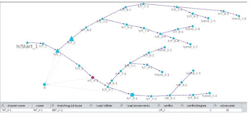
YPERTENSIONFig. 5. The interactive conflict explorer
figure, after obtaining all of the possible conflicts we assigned them arbitrary severities and added possible weights of the edges (describing the time between each node). The user can click a node to select it and access information regarding the conflicting nodes, the severity, etc. . . ; the starting node’s name is written in a bigger font, and the selected node is in red. The interface (based on Cytoscape [24]) interacts with the back-end, and then represents nodes with more severe conflicts as bigger. Both event structures are represented, and the user can double-click on one of them to collapse it (as is the case for the diabetes one in the lower-left corner of the figure, where only the hypertension is expanded). In this case, fainter lines going from the expanded structure to the collapsed one denotes the presence of conflicts. When the user expands the collapsed event structure, they can see the edges between the two structures representing the conflicts, in addition to the causality ones. Moreover, the optimal execution path (i.e., that minimising conflicts) is highlighted by triangle-shaped nodes, to suggest a possible future therapy to the user. Full details of the example cannot be shown here for space reasons. We refer the interested reader to our webpage4.
5
R
ELATED WORKSeveral formal representations of CPs have been borrowed from computer science. We can distinguish two categories. The first one is a direct formal modelling of CPs, while the second passes through a formal analysis of BPMN, as an intermediate notation from CPs to formal models. Han et al. [11] and Yang et al. [27] use Performance Evaluation Process Algebra (PEPA) [13] combined with coloured stochastic Petri nets for computing CPs. Clinical Pathway PEPA (CPP) [11] makes it possible to analyse, simulate, and optimise the CPs quantitatively. The main view of this analysis of CPs is to figure out bottlenecks and optimise allocation of hospital resources, such as medical staff and equipment. In [27], PEPA is also employed for the analysis of CPs, and essentially only addresses resource allocation. Note that our use of CPs here is very different as we are describing evidence-based proce-dures for the treatment of well understood chronic conditions. Our pathways as documented by NICE do not include probabilities and a quantitative analysis is thus not applicable. BPMN is used in many domains and has a natural semantics defined in terms of Petri nets [10]. Our use of labelled event structures in our work is in line with this semantics,
4. https://sites.google.com/site/tase8prfafyz7v/
since event structures can be understood as the unfoldings of Petri nets [19]. Further different approaches provide a semantics for BPMN based on Event-B [6] and PROMELA [26] making it possible to apply the underlying techniques for property verification. In the case of using PROMELA, the model checker SPIN [14] enables the verification of livelocks, deadlocks and LTL properties over BPMN mod-els. The problem of automated detection and resolution of pathway conflicts in patients with multimorbidity is gaining considerable attention. In [15], the authors look at medication conflicts specifically and use the SMT solver Z3 to find the conflicts and automatically suggest alternatives based on a notion of score associated to medications. Constraint logic programming (CLP) is proposed to express and deal with conflicts in [18] . While CLP solvers and SMT solvers have fundamental similarities, their expressiveness, background technologies and domains of application differ. With the efficiency of the current, mutually competitive, SMT solvers constantly growing, their lower expressiveness is getting more and more effectively compensated. And our hybrid approach adds to this compensation, with the availability of the highly expressive HOL language.
6
C
ONCLUSIONSThe problem of combining multiple clinical pathways for pa-tients with multimorbidity poses a broad range of challenges. It is important to find a combination of formalisms able to capture pathways, reason about their possible combinations and highlight problems. In this paper, we proposed an automated approach which addresses these challenges. The front-end module exposes the BPMN format to the user. The motivation for the choice of BPMN is that it is widely adopted for process modeling in industry and economy; its application to the healthcare domain has been intensively studied in the last years and, in particular, has been found to be suitable for the modeling and imaging of actual CPs [23]. While the current graphical representation is still too prim-itive to be directly usable by domain experts, it is a first step, upon which interactivity (e.g., zooming on relevant portions of the representation) and filters (e.g., displaying only events related to selected conflicts) are being added in order to address the problem of the exceeding number of conflicts potentially being presented to the user, with the aim of making it human-manageable.
our LES definitions in both higher-order logic and SMT code. Indeed, in this paper Isabelle’s SMT generator is not used for the goal it was originally conceived for (theorem proving), but rather to generate SMT code for directly solving some aspects of our main problem (combination of CPs). Finally, our approach permits to employ the LES semantics event in the presence of quantitative conflicts, adds a notion of time to the execution of pathways, and permits to suggest to the user executions which minimise the conflict. There are several fronts for possible future work; first, the idea of exploiting Isabelle’s internal SMT generator to check the correctness of SMT code can be, we believe, far-reaching, and will be used to cover further SMT developments. Secondly, the back-end execution time is, for the presented example, 3-4 seconds on average on a standard laptop, thereby giving the possibility of real-time computational adjustments based on feedback from the user and specific parameters: for instance, updating the weights on the edges to reflect the actual time separations for the nodes already visited by a given patient, or imposing the passage on nodes selected by the user.
A
CKNOWLEDGMENTSThis research is supported by EPSRC grant EP/M014290/1.
R
EFERENCES[1] N. Bjørner, A.-D. Phan, and L. Fleckenstein. “νZ-an optimizing SMT solver”. In:International Conference on Tools and Algorithms for the Construction and Analysis of Systems. Springer. 2015.
[2] J. K. F. Bowles. “Decomposing interactions”. In: Interna-tional Conference on Algebraic Methodology and Software Technology. Springer. 2006.
[3] J. K. F. Bowles and M. B. Caminati. “Mind the gap: addressing behavioural inconsistencies with formal methods”. In:2016 23rd Asia-Pacific Software Engineering Conference (APSEC). IEEE Computer Society. 2016. [4] C. M. Boyd et al. “Clinical practice guidelines and
qual-ity of care for older patients with multiple comorbid diseases: implications for pay for performance”. In:
Jama294.6 (2005).
[5] R. Braun et al. “Bpmn4cp: Design and implementation of a bpmn extension for clinical pathways”. In: Bioinfor-matics and Biomedicine (BIBM), 2014 IEEE International Conference on. IEEE. 2014.
[6] J. W. Bryans and W. Wei. “Formal analysis of bpmn models using event-b”. In:International Workshop on Formal Methods for Industrial Critical Systems. Springer. 2010.
[7] M. Burwitz, H. Schlieter, and W. Esswein. “Mod-eling Clinical Pathways-Design and Application of a Domain-Specific Modeling Language.” In:
Wirtschaftsinformatik. 2013.
[8] M. Chinosi and A. Trombetta. “BPMN: An introduction to the standard”. In:Computer Standards & Interfaces
34.1 (2012).
[9] D. R. Cok, D. D´eharbe, and T. Weber. “The 2014 SMT Competition”. In:Journal on Satisfiability, Boolean Modeling and Computation9 (2016).
[10] R. M. Dijkman, M. Dumas, and C. Ouyang. “Formal semantics and analysis of BPMN process models using Petri nets”. In:Queensland University of Technology, Tech. Rep(2007).
[11] R. Han et al. “Formal Modelling and Performance Analysis of Clinical Pathway”. In: Proceedings of the NETTAB 2011 workshop focused on Clinical Bioinformatics (NETTAB11). 2011.
[12] N. Hashemian and S. S. R. Abidi. “Modeling clinical workflows using business process modeling notation”. In:Computer-Based Medical Systems (CBMS), 2012 25th International Symposium on Computer-Based Medical Systems. IEEE. 2012.
[13] J. Hillston. A compositional approach to performance modelling. Vol. 12. Cambridge University Press, 2005. [14] G. J. Holzmann. “The model checker SPIN”. In:IEEE
Transactions on software engineering23.5 (1997).
[15] A. Kovalov and J. Bowles. “Avoiding medication conflicts for patients with multimorbidities”. In:12th International Conference on Integrated Formal Methods. LNCS 9681. Springer, 2016.
[16] J. K ¨uster-Filipe. “Modelling concurrent interactions”. In:Theoretical Computer Science351.2 (2006).
[17] F.-r. Lin et al. “Mining time dependency patterns in clinical pathways”. In:International Journal of Medical Informatics62.1 (2001).
[18] M. Michalowski et al. “Using constraint logic program-ming to implement iterative actions and numerical measures during mitigation of concurrently applied clinical practice guidelines”. In:Conference on Artificial Intelligence in Medicine in Europe. Springer. 2013. [19] M. Nielsen, G. D. Plotkin, and G. Winskel. “Petri Nets,
Event Structures and Domains, Part I”. In:Theoretical Computer Science13 (1981).
[20] T. Nipkow, L. C. Paulson, and M. Wenzel.Isabelle/HOL: a proof assistant for higher-order logic. London, UK: Springer-Verlag, 2002.ISBN: 3-540-43376-7.
[21] J. OMadadhain et al. “Analysis and visualization of network data using JUNG”. In: Journal of Statistical Software10.2 (2005).
[22] Polypharmacy Guidance (2nd Edition). Scottish Govern-ment Model of Care Polypharmacy Working Group, 2015.
[23] H. Scheuerlein et al. “New methods for clinical pathways-business process modeling notation (BPMN) and tangible business process modeling (t. BPM)”. In:
Langenbeck’s archives of surgery397.5 (2012).
[24] P. Shannon et al. “Cytoscape: a software environment for integrated models of biomolecular interaction networks”. In:Genome research13.11 (2003).
[25] G. Winskel and M. Nielsen. “Models for Concurrency”. In:Handbook of Logic in Computer Science, Vol. 4,Semantic Modelling. Oxford Science Publications, 1995. Chap. 1. [26] S. Yamasathien and W. Vatanawood. “An approach to construct formal model of business process model from bpmn workflow patterns”. In:Digital Information and Communication Technology and it’s Applications (DICTAP), 2014 Fourth International Conference on. IEEE. 2014. [27] X. Yang et al. “Modelling and performance analysis of