Polarisation distribution for Internal Conical Diffraction and the
Superposition of Zero and First Order Bessel Beams
D. O’Dwyer
1*, C. Phelan
1, Y. Rakovich
1, T. Cizmar
2, K. Dholakia
2,J. F Donegan
1, J. G Lunney
11School of Physics, Trinity College Dublin, Dublin 2 Ireland
2School of Physics and Astronomy, St Andrews Scotland
ABSTRACT
Internal conical refraction leads to the formation of zero (J0) and first order (J1) Bessel beams in superposition. The
(J0) beam retains the input circular polarisation and the (J1) has opposite polarisation but with a single phase change
around the beam axis giving it ħ optical angular momentum per photon. This results in the conical beam having ½ ħ
net optical angular momentum per photon. This provides a simple system in which a beam of 0, ½ and ħ optical angular momentum can be easily generated and selected with use of only a circular polariser. In the far field the characteristic Bessel beam structures are formed and can be made non-diverging with use of a lens. We report the formation of non-diverging Bessel beam of core diameter (a) of 5.7µm over a maximum non-diverging core length of 1(±.05)mm. However due to the fine structure of the conical beam at its beam waist position two cores are produces and are of opposite phase.
Keywords: Conical refraction, Biaxial, Bessel beams, optical orbital angular momentum
* Further Author Information:
Email :[email protected]; ph: +353 (0)1 8964093
THEORY
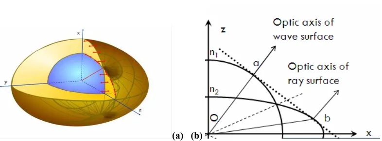
Internal conical refraction occurs when light propagates down the optic axis of a transparent biaxial medium. If the input beam is a planar Gaussian beam the biaxial crystal changes the electric field distribution of the beam to be a cone of light within the crystal and a cylinder of light upon exiting the crystal (1) (2). A biaxial crystal is described by a
Optic axis of
wave surfaceOptic axis of
ray surface
x
giving the resulting direction of propagation for the given ray, (one ray for each wave, two waves for each direction). This is more easily shown in fig (1-a) where the wave surface is shown along with the appropriate polarisations and a clearly defined optic axis. The cone of internal conical refraction is formed by a plane perpendicular to the direction of the wave surface optic axis. This plane touches an infinite amount of points on the ray surface tracing out a circle. This plane is shown in fig (1-b), as is the cone of internal conical refraction. Light propagating in this direction forms a cone of light within the crystal and a cylinder of light upon exiting the crystal (4). Conversely the optic axis of the
ray surface defines the cone of external conical refraction. The resulting conically refracted ray has a unique polarisation and phase distribution due to the infinite amount of points on the wave surface. The polarisation distribution is shown in fig (2). At the waist of the input beam a sharp double ringed structure appears with a unique polarisation distribution of π/2 rotation of phase around the rings. The fine structure of the focal image plane reveals that this double ringed structure is separated by a dark Poggendorff ring this is due to the finite size of the input beam
(5). This occurs due to the finite size of the input beam giving a corresponding finite region around the optic axis
resulting in the observed beam structure. The Poggendorff ring corresponds to the point of contact of the two sheeted wave surface (i.e. the optic axis) which has zero area hence zero intensity
(a) (b)
Figure 1: (a) Double sheeted wave surface with optic axis clearly defined (b) 2-D slice of the ray surface with the differences in refractive indices exaggerated. This is the cone of internal conical refraction. The optic axis of the wave surface defines this plane.
Figure 2 Distribution of polarization from cone of refraction.
Conical diffraction as first put forward by Beslki (6) and Berry (7) involves consideration of off axis waves i.e. the part
[image:2.612.115.508.346.492.2]intersection as in fig(1-b) (7). From geometric optics we know the phase and polarisation distributions fig (1).
Knowing this the diffraction of the beam can thus be calculated with a transformation of a plane wave given by
) P ( d AP))] ± kP z( R P [ik( ± 2 1/2
exp ⋅ − (1)
With d± (P) is the polarisation of the plane wave, with two values due to the polarisation rotation around the optic axis. With the refractive index for a given wave direction is given by, with (A) being the semi angle of the crystal
k))
±
A(k
+
(
n
=
n(k)
21
x (2)With the z axis being the optic axis and
k
x,ky off axis wave vectors,
2 y x
+
k
k
=
k
2 (3)After using the paraxial treatment of the wave to describe the propagation of a beam through a biaxial medium the emergent field is given by:
⎟
⎟
⎠
⎞
⎜
⎜
⎝
⎛
⎟⎟
⎠
⎞
⎜⎜
⎝
⎛
−
⎟
⎟
⎠
⎞
⎜
⎜
⎝
⎛
2 1 2 1e
e
Cos
θ
Sin
θ
Sin
θ
Cos
θ
B
+
e
e
B
=
E
0 1 (4)Where: e1 e2 are the input polarisation vectors. B0 and B1 are given by.
{
}
{
}
(kR)
)J
(kR
ikz
w
k
dkk
=
B
0 0 2 2 0cos
1/2
exp
1/2
exp
∫
−
−
(5){
}
{
}
(kR)
)J
(kR
ikz
w
k
dkk
=
B
0 1 2 2 1sin
1/2
exp
1/2
exp
∫
−
−
(6)J0 and J1 are the Bessel functions of zero and first order. B0 has the same polarization as the incident beam and B1 has a phase change of polarization around the beam. For right circularly polarized incident light B1 is left circular & vice versa. According to Berry (7) when (R) is close to (R0) the integrals B0 and B1 are approximately equal resulting in the
(
R
R
0)
J
B
0∝
0,
,B
1∝
J
1(
R
,
R
0)
(7)And for circular input light we have a superposition of Bessel beams with opposite circular polarizations.
(
)
(
)
⎟⎟
⎠
⎞
⎜⎜
⎝
⎛
⎟⎟
⎠
⎞
⎜⎜
⎝
⎛
Θ
−
Θ
Θ
Θ
⎟⎟
⎠
⎞
⎜⎜
⎝
⎛
i
Cos
Sin
Sin
Cos
R
R
J
+
i
R
R
J
=
E
0,
01
1,
01
= Liθ R
+
e
J
e
e
J
0ˆ
1ˆ
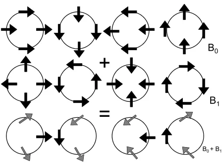
(8) [image:4.612.200.424.274.439.2]Using equation (8) the polarisations of the individual beams can be mapped out for when B1≈B0 (beam waist of input Gaussian beam)
Figure 3: Polarisation distribution for one ring at beam waist, other ring is of opposite phase and polarisation direction. B0 retains input polarisation and B1 has opposite polarisation but with a phase change across beam.
Over λ the resultant beam contains a ½ phase change around the beam resulting in a spiralling Poytings vector. This distribution only strictly holds true at B0 = B1.
The presence of orbital angular momentum in a conically refracted beam was first presented by Berry (8). In this he
predicts that the conical beam changes the solely spin input momentum into half integer purely orbital angular momentum hence exerting a torque on the biaxial medium. Orbital angular momentum can be defined by a rotation of phase around a beam axis (3), given by
e
imΘ, where (m) is the number of changes of phase around a beam axisresulting in orbital angular momentum of mħ per photon. For the polarisation distribution of our conical beam it can be seen that B0 contains no change of phase. Compared to B1which contains one change of phase around beam axis.
This results in a net orbital angular momentum of ½ ℏ per photon. Due to the conical beam having a half integer OAM the electric field will have a spiralling wave front and will have an edge dislocation in its wave front. Diffraction of the beam away from the beam waist leads to B0≠B1. The diffraction of the conical beam form the beam
waist results in a spreading of the beam and eventually a spike of intensity appears at what was the centre of the rings.
B0
B1
+
=
This is known as the axial spike. Separation of this axial spike reveals the characteristic Bessel beam distributions of zero J0 and first J1 order. These beams continue to spread and diverge as they propagate. By placing a lens at (f) away
from the conical beam waist non diverging Bessel beams will be formed over the focal length of the lens. These non-diverging Bessel beams were first introduced by Durnin (9) as ways to form propagation-invariant optical beams given
by
( )
r,t
=
E
J
( )
kr
(
i
(
kz
ω
t
)
)
E
0 0exp
−
(9)With J0 the Bessel solutions of zero order and similarly for J1. This is of the same kind as in equation (4) but with the
addition of the first order beam with the polarisation modulation around the beam. However Bessel beams are not infinitely non-diverging they do have a maximum non-diverging length called zmax. The Bessel beam core diameter is
given by (a)
π
θ
λ
J
=
a
.2
sin
0
(10)
Where J0 is 2.405 and Θ is given by
( )
f
r
=
θ
tan
(11)
Where (r) is the radius of the dark Poggendorff ring in the focal image plane and (f) is the focal length of the collecting lens.
EXPERIMENTAL
The formation of the conical beam is achieved by focusing a beam of light down the optic axis of a biaxial crystal. The input Gaussian beam is circularly polarised of either left or right handedness with a beam waist size of 18µm. A single crystal of monoclinic tungstate of KGd (WO2)4(10) was used, with its respective refractive indices at 633nm
given by (11)
n1 = 2.01169, n2 = 2.042198, n3 = 2.09510
O.OOE+OO 1.OOE-04 2.OOE-04 3.OOE-04
Radial Distance (m)
[image:6.612.136.474.78.181.2]Focal Image Plaae segemerit
Figure 4: To form non diverging Bessel beams a lens is places at its focal length away from the focal image plane above.
The diameter of the rings at the focal image plane is given by the semi angle of the crystal and the length of the crystal. R is the radius of the Poggendorff rings upon exiting the crystal, resulting in a theoretical ring radius of 5.9015x10⁻⁴m.
(12)
Using numerical calculation the experimental intensity distributions can be compared to the theoretical intensity distributions using equation (4)
Theoretical Experimental
Semi Angle 19.6mRad 20.04mRad
[image:6.612.210.440.366.493.2]Ring Radius 5.9012E-4m 6.012E-4m
Table 1: Conical refraction properties due to crystal dimensions compared with theory
(a) (b)
[image:6.612.88.528.523.665.2]RESULTS
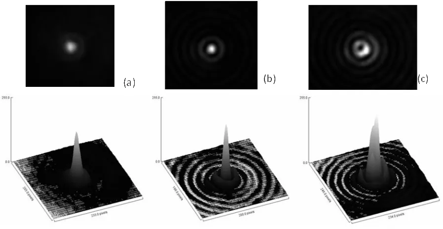
The generation of propagation invariant Bessel beams results in a central core of width (a) whose dimensions remains constant over zmax. For a core size (a) of 6µm a lens with a focal length of 8mm was used. Profiling the beams gives
zmax to be .36(±.05)mm per core over a distance of 1.1mm. Fig 6 shows the beam profiles and surface plots of
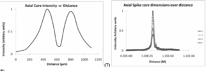
[image:7.612.78.527.243.475.2]intensity. Fig 7 shows the Bessel beams core intensity over the 1.1mm range along the propagation direction. It clearly shows the presence of two beam core due to presence of the double ring structure in the focal image plane. Fig 8 shows the beam profile of one of the cores over .36mm which has a constant core width of 5.7µm.
Axial Core intensity -v- Distance
0 200 400 600 800 1000 1200
Distance (sm)
Axial Spike core dimensions over distance
i_I
O.OOE+OO 5.OOE-O5 1.OOE-04 1SOE-04
Distance (M)
DISCUSSION
The formation of zero and first order Bessel beams by conical diffraction is clearly demonstrated via diffraction of the sharp double ring structure from the beam waist. These beams which are in superposition can easily be separated due to their individual polarisation distribution revealing two beams, one with only spin angular momentum and a beam with a phase change across the beam giving it ħ optical orbital angular momentum. However when they are in superposition the conical beam contains only ½ ħ OAM with only ½ phase change around the beam. These beams can also be easily modified via a lens to form non diverging beam cores over long distances compared to Gaussian beam propagation. Along the beam axis two beam cores are created of opposite phase separated by a region of low core intensity. This Bessel beam core has a region of zero intensity along the propagation direction due to the presence of the Poggendorff dark ring in the focal image plane. Both cores are of equal length and intensity which is due to the fact that both inner and outer rings contains equal amount of energy (7). A beam core width of 5.7um was formed with
two beam cores of .36mm in length. Trapping experiments are planned to provide a viable optical trapping system that is easily switch able between beam of zero, one and ½ ħ OAM. These Bessel beams have also been gaining interest in various fields (12) (13) (14). Recent work has shown interest in these half integer states with regards to quantum
entanglement and quantum information processing.
[image:8.612.86.524.75.226.2](7) (8)
Figure 8: Plot of Intensity of Bessel Beam cores along propagation direction.
References
[1] Hamilton.W.R ,"Third Supplement to an Essay on the System of Rays." , Royal Irish Academy, Vol. 17, 1-144(1837 )
[2] Lloyd.H, "On the Phænomena presented by Light in its Passage along the Axes of Biaxal Crystals." s.l. : Philosophical Magazine, Vol. 2, pp. 112-120(1833)
[3] Ditchburn, R.W. [Light] (1976)
[4] Allen L., Padgett M.J., Barbiker M. , “The orbital angular momentum of light”, [Progress in Optics], E. Wolf , Elsevier (1999)
[5] Poggendorff, J. C., "Ueber die konische refraction." . Pogg. Ann., 461-462(1839)
[6] Belski A M, Khapalyuk. ,"Internal conical refraction of bounded light beams in biaxial crystals," Opt. Spect., Vol. 44, 436-439(1978)
[7] Berry, M V.,"Conical Diffraction Asymptotics: Fine Structure of Poggendorff rings and axial spike " , Journal of Applied Physics A, Vol A , 289-300(2004)
[8] Berry M.V. Jeffery M.R., Mansuripur M. , "Orbital and spin angular momentum in conical diffraction," .Journal of Optics A , Pure and Applied Optics, Vol. 7,685-690(2005)
[9] Durnin J., Miceli J.J. , "Diffraction free beams," 15, s.l. : Physics Review Letters, 1987, Vol. 58,1499-1501 (1987)
[10] Croptics. Crystal Supplier. Barcelona, Spain : s.n.
[11] Pujol M.C., Rico M., Zaldo C., Solé R., Nikolov V., Solans X., Aguilo M., Díaz F. , "Crystalline Structure and Optical Spectroscopy of Er3+ -doped KGd(WO4)2 single crystals.": Applied Physics B Lasers and Optics Vol. 68, 187-197 (1999)
[12] Arlt J., Dholakia K., Allen L., Padgett, M. J. , "Effiency of Second Harmonic Generation with Bessel Beams," Physical Review A, Vol. 60, 2438 (1999)
[13] Roskey, V. Garcés-Chávez D. "Optical Levitation using Bessel Light beams" App Phy Letters, Vol. 85 (18) , 4001-4003 (2004